Full Terms & Conditions of access and use can be found at
http://www.tandfonline.com/action/journalInformation?journalCode=taut20
Automatika
Journal for Control, Measurement, Electronics, Computing and
Communications
ISSN: 0005-1144 (Print) 1848-3380 (Online) Journal homepage: http://www.tandfonline.com/loi/taut20
Visual servoing for low-cost SCARA robots using an
RGB-D camera as the only sensor
P. Ðurović, R. Grbić & R. Cupec
To cite this article: P. Ðurović, R. Grbić & R. Cupec (2017) Visual servoing for low-cost SCARA robots using an RGB-D camera as the only sensor, Automatika, 58:4, 495-505, DOI: 10.1080/00051144.2018.1461771
To link to this article: https://doi.org/10.1080/00051144.2018.1461771
© 2018 The Author(s). Published by Informa UK Limited, trading as Taylor & Francis Group
Published online: 08 Jun 2018.
Submit your article to this journal
Article views: 38
VOL. 58, NO. 4, 495–505
https://doi.org/10.1080/00051144.2018.1461771
REGULAR PAPER
Visual servoing for low-cost SCARA robots using an RGB-D camera as the only
sensor
P. Ðurović, R. Grbić and R. Cupec
Faculty of Electrical Engineering, Computer Science and Information Technology Osijek, Osijek Croatia ABSTRACT
Visual servoing with a simple, two-step hand–eye calibration for robot arms in Selective Compli-ance Assembly Robot Arm configuration, along with the method for simple vision-based grasp planning, is proposed. The proposed approach is designed for low-cost, vision-guided robots, where tool positioning is achieved by visual servoing using marker tracking and depth infor-mation provided by an RGB-D camera, without encoders or any other sensors. The calibration is based on identification of the dominant horizontal plane in the camera field of view, and an assumption that all robot axes are perpendicular to the identified plane. Along with the plane parameters, one rotational movement of the shoulder joint provides sufficient information for visual servoing. The grasp planning is based on bounding boxes of simple objects detected in the RGB-D image, which provide sufficient information for robot tool positioning, gripper orien-tation and opening width. The developed methods are experimentally tested using a real robot arm. The accuracy of the proposed approach is analysed by measuring the positioning accuracy as well as by performing grasping experiments.
ARTICLE HISTORY Received 14 November 2017 Accepted 29 March 2018 KEYWORDS
Visual servoing; hand–eye calibration; grasp planning; SCARA; low-cost robot arm
1. Introduction
Although robot sales increasingly grow every year, robots are today mostly used in the industry [1]. The goal of making robots more affordable to a wide com-munity of developers as well as for everyday applica-tions motivated a number of research teams to design low-cost robotic solutions [2–4]. The research pre-sented in this paper contributes to this goal by propos-ing a method for vision-based control of a particular type of low-cost robot arms. The presented work com-prehends hand–eye calibration for the purpose of visual servoing and grasping of simple convex objects.
In this paper, low-cost robot manipulators based on stepper motors which do not have absolute encoders or any other proprioceptive sensors for measuring joint angles and rely on visual feedback only are considered. Lack of absolute encoders implies that tool positioning cannot be performed by inverse kinematics, since abso-lute joint angles cannot be known or preset. Therefore, in this paper, an approach for relative tool positioning based on computer vision is proposed. The target posi-tion of the tool is determined by detecting objects of interest in an image of the robot’s workspace acquired by an RGB-D camera, while the current tool position is obtained by localization of a marker mounted on the robot arm close to the end effector using a vision-based marker tracking software. The visual servoing method, proposed in this paper, computes changes of
joint angles required to move the tool from its current position to the target position. The method is designed for robots in Selective Compliance Assembly Robot Arm (SCARA) configuration, which is common in robot manipulation since it is advantageous for pla-nar tasks [5], such as assembly or pick-and-place. In the particular configuration, the current and the tar-get tool position can be represented by points on two circles of different radii centred in the shoulder joint axis. The distance between the tool and the shoulder joint axis is adjusted by changing the elbow joint angle, while the shoulder joint moves the tool along the circle until the target position is reached. Considering imper-fection of the robot motors as well as the uncertainty of the information about the pose of the shoulder axis w.r.t. the camera, the tool position is corrected itera-tively until the given position is reached within a spec-ified tolerance, which is validated by the robot’s vision system.
The pose of the shoulder joint axis w.r.t. the cam-era, required by the proposed visual servoing approach, is achieved by a novel, simple and fast, two-step hand–eye calibration. Since the proposed visual ser-voing approach is based on the tool distance w.r.t the shoulder joint axis and its position on the circle centred in this axis, it can be applied only in the eye-to-hand configuration, where the camera is mounted in a fixed position w.r.t. the shoulder joint axis. The eye-to-hand
CONTACT P. Ðurović [email protected] Faculty of Electrical Engineering, Computer Science and Information Technology Osijek, Osijek Croatia
© 2018 The Author(s). Published by Informa UK Limited, trading as Taylor & Francis Group
This is an Open Access article distributed under the terms of the Creative Commons Attribution License (http://creativecommons.org/licenses/by/4.0/), which permits unrestricted use, distribution, and reproduction in any medium, provided the original work is properly cited.
configuration is suitable for small robot arms, where the camera couldn’t be mounted on the robot’s end effector. Furthermore, the eye-to-hand configuration is typical for anthropomorphic robots, as well as for bio-logical systems, i.e. humans and animals, where the vision system positioned high above the ground pro-vides a wider overview of the environment. For the same reason, this configuration is suitable for mobile robot manipulators, where the same camera can be used for robot localization, search for the object of inter-est in the robot’s environment and manipulation with objects.
We consider the SCARA configuration, where all joint axes are parallel to the gravity axis, and assume that the objects of interest are positioned on a hori-zontal plane, referred to in this paper as the support-ing plane. The proposed hand–eye calibration method identifies the dominant plane in the camera field of view and determines the shoulder joint axis orientation as the vector perpendicular to this plane. Besides the supporting plane information, the proposed calibration method requires only one rotational movement by the shoulder joint. Assuming that the elbow joint remains still, a shoulder joint movement slides the tool along a circle centred in the shoulder joint axis. By knowing the change in the shoulder joint angle, the centre of this circle w.r.t. the camera can be determined. The shoul-der joint axis is determined as the line perpendicular to the supporting plane, which passes through the circle centre. The simplicity of the proposed method makes it suitable for often recalibration.
In order to obtain a complete vision-based tool posi-tioning system for SCARA robots, we developed a sim-ple method for grasp planning, where the target tool position is computed based on visual input. The pro-posed grasp planning approach consists in detecting simple convex objects in an RGB-D image of the scene, creating the object bounding boxes and computing the target tool position, orientation and opening width of the gripper based on the bounding box of one of these objects. The tool orientation is determined according to the shape and orientation of the object of interest. More precisely, the region of the object’s surface of the small-est curvature, approximately perpendicular to the sup-porting plane, is considered to be suitable position for the contact points of the gripper fingers. Low curvature regions on the object’s surface are detected by segment-ing this surface into approximately planar patches. The grasp planning method proposed in this paper, how-ever, has some limitations: (i) it is assumed that the tool has only one rotational DoF and that objects can be grasped only from above, (ii) grasping is possible only for convex objects and (iii) stable grasp is not guaran-teed even for convex objects. Nevertheless, the class of objects to which the proposed method can be applied is still wide and the efficiency of this method is clearly its advantage in comparison to more general, but also
more complex approaches, some of which are reviewed in Section2.
There are two contributions of this paper. The first contribution is a novel visual servoing approach for SCARA robots without absolute encoders and with a camera as the only sensor, which uses the informa-tion about the shoulder joint axis obtained by a simple hand–eye calibration method. Another contribution is a method for grasp planning, suitable for simple con-vex objects detected in RGB-D images. The proposed methods are experimentally evaluated on a set of visual servoing and grasping experiments. These experiments are performed using a low-cost, vision-based robot arm in SCARA configuration.
The paper is structured as follows. In Section 2, we present an overview of the current state of the art in the fields of low-cost robotics, visual servoing, hand–eye calibration and grasp planning. The pro-posed visual servoing approach with the associated cal-ibration method is explained in Section3. In Section4, the grasp planning method based on visual input is proposed. Finally, an experimental evaluation of the proposed approaches is presented in Section 5. The last section brings a conclusion and options for future research.
2. Related research
This section provides a review of published research closely related to the work presented in this paper. The reviewed research is from the fields of low-cost robots, hand–eye calibration, visual servoing and vision-based grasp planning.
Low-cost vision-guided robot manipulators: Design of low-cost robots has been a topic of interest of several research groups [2–4]. In [2], a coun-terbalance mechanism, which reduces cost, is pro-posed. The presented setup, however, doesn’t include vision. A low-cost, custom-made, 6 DoF Pieper-type robotic manipulator with eye-in-hand configuration is proposed in [3]. In [4], a vision-based robot system consisting of an off-the-shelf 4 DoF robot arm and a camera is presented. This system is based on visual servoing without encoders, which uses a hand–eye cal-ibration method requiring two movements of the robot arm.
Hand–eye calibration and visual servoing:In [3,6–14] calibration methods for the eye-in-hand configuration are proposed. In [8], an eye-in-hand calibration method is proposed, consisting of a small number of steps, where a light plane projected by a laser on the end effec-tor is being used in calibration. A study which performs eye-in-hand calibration and intrinsic camera calibra-tion at the same time is proposed in [9]. This method relies on a single point, which must be visible during the calibration. The point is not placed on the robot itself, but in the robot’s environment. In [10], a combined
internal camera parameter and eye-to-hand calibration approach, which uses a calibration panel, is proposed. This approach uses A4 size printed checkerboard as the calibration panel, which is mounted on the robot end effector. However, this method isn’t suitable for smaller robot arms and automatic recalibration, because of the size of the calibration panel. A more complex calibra-tion, using global polynomial optimizacalibra-tion, is given in [11], and it uses eye-in-hand camera configuration. In [3], visual servoing is implemented on a custom developed robot arm. In this setup, an eye-in-hand con-figuration is considered, where the pose of the target is extracted from a 2D image by photogrammetry. In [4], a visual servoing for absolute positioning is pre-sented. The hand–eye calibration method consists of two rotational movements forming a triangle of points sufficient for computing the pose of the robot reference frame (RF) w.r.t. the camera. However, due to the small number of measurements used in this computation, a high accuracy cannot be achieved. Furthermore, this method requires the robot to be positioned in an appro-priate initial position before performing the hand–eye calibration, and it is not clear how this could be done automatically.
Grasp planning:In a number of researches, the posi-tion of the grasped object is extracted from a 2D image based on the object contours [15,16]. In order to avoid computations in 3D, computations are some-times transformed into 2D space [17]. In [18], along with a stereo camera, laser scanners are used to obtain the 3D position of objects in the scene. Information about 3D geometry of the scene is clearly useful in robotic manipulation, which is being demonstrated in the results of recent computer vision research [19–24]. In order to achieve a real-time performance, a database of graspable objects is created in [25], which allows off-line determination of a successful grasp for a cer-tain object. The graspable objects are represented by CAD models or complete 3D scans. The authors of the work presented in [26] implemented the grasp planning for the non-convex objects by the object decomposi-tion within the modecomposi-tion planner tool Move3D [27]. A method which computes grasps based on bounding boxes is given in [17]. A set of graspable bounding boxes with different properties, such as size and orien-tation, is computed off-line and stored in a database. For a given bounding box of an object detected in the scene, a similar bounding box is found in the database and, if possible, grasping is performed with an line computed gripper configuration. The off-line computation time needed was nearly nine min-utes. The approach to grasp planning used in [28] is to determine the gripper configuration by optimiza-tion. In the case of complex grasp planning tasks, the grasp proposals are evaluated by simulators. Among the other grasping simulators, Graspit! [29], being one of the most famous, is used by Xue and Dillmann
[17], Marton et al. [18] and Kragic et al. [25]. In [25], Graspit! is used to integrate real-time vision with online grasp planning, where it executes stable grasp on objects and monitors the grasped object’s trajectory as it moves.
3. Tool positioning using an RGB-D camera This section describes the robot tool positioning approach based on visual servoing with a belong-ing novel hand–eye calibration method. The discussed approach consists of determining the current tool posi-tion and the target posiposi-tion w.r.t. the robot shoulder joint axis using computer vision and changing the joint angles until these two positions match within a user-specified tolerance.
3.1. Measuring the marker position using an RGB-D camera
The developed methods are designed for a robot manipulator with a marker placed on the robot arm. The centre of the marker is used to determine the cur-rent position of the robot end effector. Since an RGB-D camera is used in the considered robot system, two measurements of the marker distance w.r.t. the camera are available: the one obtained by the RGB image using a marker tracking software and the other obtained by the depth sensor. The marker tracking software detects the marker in the RGB image and computes its position w.r.t. the camera RF according to the size of the marker in the image and the known actual marker size speci-fied by the user. This position is defined by coordinates (xRGB,yRGB,zRGB). The depth sensor of the RGB-D
camera assigns depth values to the image points. The depth value of an image point is itsz-coordinate w.r.t. the camera RF, where thez-axis of this RF is parallel to the camera’s optical axis. The depth valuezd assigned
to the image point representing the marker centre is an alternative measurement of thez-coordinate of the marker centre. We perform fusion of the two measure-ments of the marker centrez-coordinate,zRGBandzd,
by taking into consideration the uncertainty of both measurements. In order to estimate the uncertainty of the market tracking software, the marker is moved along a vertical line by controlling the translational joint of the robot. The orthogonal distance regression (ODR) line is fitted to the set of points representing the marker centre positions obtained by the marker tracking soft-ware. For each of these marker centre positions, the dif-ference between itsz-coordinate and thez-coordinate of the point on the optical ray passing through the marker centre closest to the ODR line is computed. This difference is regarded as the error in measurement of zRGB. The variance of this error, representing a
mea-sure of the uncertainty ofzRGB, is denoted byσRGB2 . In
is placed in the camera field of view, the points belong-ing to this surface are identified in the depth image and the uncertainty ofzdis estimated by a statistical analysis
of the deviations of these points from the least-squares plane fitted to them. The discussed planar surface is identified using the standard random sample consensus (RANSAC)-approach [30]. Each point belonging to this surface is projected onto the least-squares plane along the optical ray passing through this point. The differ-ence between the z-coordinates of a particular point and its projection is regarded as the measurement error. The variance of this measurement errorσd2 is used as a measure of uncertainty of zd. Given two
measure-ments,zRGB andzd and their variances σRGB2 andσd2,
the optimalz-coordinate is computed by
z= zd σ2 d + zRGB σ2 RGB 1 σ2 d + 1 σ2 RGB . (1)
Thisz-coordinate is used to correct the other two coor-dinates of the marker centre by scaling them using the scaling factor
s= z
zRGB. (2)
Assuming that the marker is clearly visible, the described method provides the 3D position of the marker w.r.t. the camera RF denoted byCpM.
Compu-tation of the marker position is given in Appendix1. 3.2. Visual servoing
Before explaining the developed approaches, the nota-tion used in the rest of this paper is introduced. In this paper,BtA denotes the translation vector defining the
position of an RFSAw.r.t. an RFSB. Furthermore, the
following notation is used for RFs:Rrepresents robot,C camera,Mmarker RF andGrepresents RF of the object bounding box. The position of a pointAw.r.t. the RFB is denoted byBpA.
There are two common variants of the SCARA con-figuration: the one where the first joint is translational and the other two are rotational, and the other with the first two rotational joints, and the third translational joint. In this paper, it is assumed that the first joint is translational, but the same method is applicable to both of these two configurations.
The purpose of visual servoing is to compute the changes of joint variables required to move the marker attached to the robot arm from its current position to a given target position. The current marker position is measured using the approach described in Section3.1, while the target position is determined by the grasp planning method presented in Section4. The proposed visual servoing approach requires the pose of the shoul-der joint axis w.r.t. the camera RF, defined by unit vector
Cz
R, representing the axis orientation, and vectorCtR,
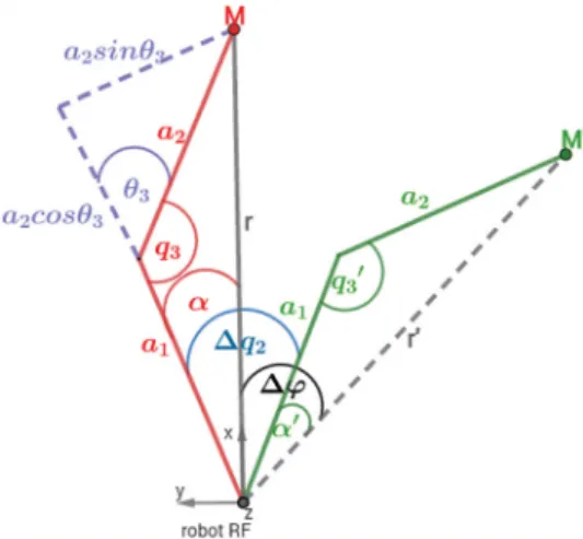
Figure 1.Robot arm in the current (M) and target (M’) position.
representing the position of a reference point on the considered axis w.r.t. the camera RF. Vectors CzR and Ct
Rare obtained by the hand–eye calibration described
in Section3.3. Visual servoing can be performed multi-ple times with the same parametersCz
RandCtRas long
as there is no need for recalibration.
Let us consider the SCARA configuration geome-try shown in Figure1, wherea1anda2 represent the
lengths of robot arm links. In order to explain the considered visual servoing approach, we introduce the robot RF centred in a reference point of the shoulder joint axis, withz-axis identical to the shoulder joint axis. We define the other two axes of the robot RF according to the current marker position. Thex-axis is directed towards the marker, as shown in Figure1. In each cor-rection step of the visual servoing,x-andy-axes of the robot RF are redefined.
Let M be the current marker position andM the target marker position. The visual servoing computes the required change in vertical positionz, which is achieved by the first translational joint, as well as the required changesq2andq3of the second and the
third rotational joint. The changes in the rotational joints are computed based on the geometry shown in Figure1.
The required change of the translational joint vari-able,z, represents the difference in thez-coordinate of the robot RF and is independent of the other joint variables. To computez, only the current coordinate zand the target coordinatez of the marker w.r.t. the robot RF are required. Therefore,zis computed by
z=z−z, (3)
where
z=CzR(CpM −CtR) (4)
andzis computed analogously.
The required change in the elbow jointq3is
com-puted by
where q3 represents the current angle of the elbow
joint, and it is calculated as in the standard planar robot manipulator configuration [31]. Analogously,q3 represents the angle of this joint in the target position.
The required change in the shoulder joint q2 is
computed by
q2=α−α+ϕ, (6)
whereϕrepresents the angle between vectorsrand r, shown in Figure1, whileαis computed by
α=asina2sinq3
r (7)
andαis computed analogously.
Vectorr, connecting the shoulder joint axis and the current marker position, is computed by
r=CpM−CtR−z·CzR, (8)
and vectorr, connecting the shoulder joint axis and the target marker position, is computed analogously tor.
This algorithm is repeated iteratively until the marker reaches the target position, within a given toler-ance. This tolerance represents the maximal acceptable distance between the target and the obtained position. It shouldn’t be zero because of the measurement noise, backlash and limited robot precision, which prevent the robot to achieve the exact target position and could cause the visual servoing to end in an infinite loop.
The positioning accuracy of the considered robot system depends on the accuracy of the marker position measured by vision, and on the accuracy of the shoul-der joint axis orientation w.r.t. the camera estimated by detection of the supporting plane, as explained in Section 3.3. The accuracy of determining the refer-ence pointCtRdoesn’t impact the positioning accuracy,
but impacts the number of visual servoing iterations. A more accurate estimation of CtR results in fewer
iterations.
3.3. Hand–eye calibration for relative positioning Parameters of the shoulder joint axis, CzR and CtR,
required for the visual servoing algorithm described in Section3.2, are determined by the calibration proce-dure described in this section. The calibration method proposed in this paper determines the shoulder joint axis orientation by detecting the supporting plane. The position of this axis is defined by a reference point, which is an arbitrary point on this axis determined by performing only one rotational movement of the shoul-der joint. The supporting plane is estimated using the RANSAC algorithm explained next. First, three ran-dom points from the RGB-D image are selected and parameters of the plane passing through those points are computed. All points belonging to that plane, within
Figure 2.Detection of the dominant plane.
a given threshold, represent the consensus set. This pro-cedure is repeated for a given number of times and the parameters of the plane with the greatest consen-sus set are selected. Finally, the least-square plane is fitted to the selected consensus set. An example of the determined supporting plane is given in Figure2. Ori-entation of the determined supporting plane normal concurs with the shoulder joint axis orientationCzR.
Now, let us consider the robot movement, where only the shoulder joint is being rotated for a known angle of rotationq2causing the marker to move from
the initial point M(0) to the final point M(1). Rota-tion of pointMabout an axis passing through a point defined by vector CtR, where the axis orientation is
defined by vectorCzR, can be described by equation
R(Cz
R,q2)·(CpM(0)−CtR)=CpM(1)−CtR, (9)
whereR(CzR,q2)denotes the rotation matrix defined
by vectorCzR and angleq2. VectorCtRcan be
com-puted by solving Equation (9) for CpM(0) andCpM(1)
obtained by the marker tracking software. The pro-posed hand–eye calibration method consists of the steps explained in Appendix2.
4. Vision-based simple objects grasp planning In this section, an approach for grasp planning based on bounding boxes of objects detected in RGB-D images is presented. It is assumed that the gripper is capable for grasping objects from above only, which is typi-cal for SCARA robots. In order to facilitate successful grasping, a suitable orientation of the gripper, its posi-tion above the object and the gripper opening width are required. The proposed grasp planning approach is limited to simple convex objects. Objects of interest are detected in an RGB-D image of the robot’s workspace using the method presented in [32]. Basically, the RGB-D image is segmented into planar patches and adjacent planar patches are aggregated into objects using a cri-terion based on convexity. Hence, the result of this method is one or multiple objects, each represented by a set of planar patches. Considering only grasping from
Figure 3.Marker RF and tool orientation.
above and assuming that the objects lie on the sup-porting plane, it is assumed that a low curvature object surface, oriented at a steep angle w.r.t. the supporting plane, provides a stable grasping point. Grasp vector g, which defines the gripper orientation, as shown in Figure3, is perpendicular to the supporting plane and the normal of one of the objects planar patches. Hence, it can be computed by
g= ns×ni
ns×ni, (10)
wherensrepresents the normal of the supporting plane,
andni represents the normal of the ith planar patch
of the grasped object. The planar patch used for com-puting vectorg is chosen in such a way that g com-puted by Equation (10) has the minimum orientation uncertainty.
The uncertainty of g depends on the uncertainty ofni as well as on its orientation. The uncertainty of
ni is estimated using the approach described in [33].
Covariance matrixp of all points belonging to the
considered patch is computed. The eigenvector corre-sponding to the smallest eigenvalue ofprepresents the
planar patch normal, while the other two eigenvalues describe the distribution of points in the planar patch plane. Those two values are greater for larger planar patches corresponding to low-curvature regions of the object’s surface. The planar patch normal uncertainty is represented by the following equation:
ni= ˆni+Misi, (11)
where ni is the true value of the planar patch
nor-mal, nˆi is its measured value, M is the matrix whose
diagonal elements are the eigenvectors corresponding to two largest eignevalues of p and si is a
distur-bance vector representing the deviation ofnifromnˆiin
Figure 4.An example of bounding boxes of objects detected in the scene.
two directions perpendicular tonˆi. Covariance matrix
ni, which represents the distribution of the
distur-bance vector si, is a diagonal matrix whose diagonal
elements are approximately inversely proportional to the two greater eigenvalues ofp[33]. Hence, the larger
planar patches have smaller normal uncertainty. The uncertainty of vectorg can be estimated by propagat-ing the uncertainty of ni. The covariance matrixg,
representing the uncertainty ofg, is computed by g = dg dsi ·ni· dg dsi , (12)
where dg/dsi represents a Jacobian, computed by
sub-stituting Equation (11) into Equation (10) and partially deriving the obtained vector w.r.t. the components ofsi.
Finally, the measure of orientation uncertainty of vector gis computed as the projection ofgin the direction
perpendicular tog. This projection is computed by
σg=ugu, (13)
where u represents the unit vector perpendicular to both g and ns. Value σg is computed for every
pla-nar patch of an object and vectorgis computed using the normal of the planar patch corresponding to the smallestσg.
A stable grasp is determined by computing the bounding box of the considered object, whose sides are aligned with vectorsns,g andu. Examples of objects
detected in an RGB-D image of the robot’s workspace and their bounding boxes are shown in Figure4.
The basic idea of our approach comes from the fact that if the line connecting the grasping points passes through the object centre of gravity and if it is approx-imately perpendicular to the surface normals in the grasping points, the grasp will be stable. We assume that the object centre of gravity is close to its bound-ing box centre of gravity. Therefore, the graspbound-ing points are defined in such a way that the connection line between the grasping points passes through the bound-ing box centroid. The boundbound-ing box plane parameters provide sufficient information for computing the object centroid, a pointCpG, representing the target position
for visual servoing, i.e. the midpoint between the two gripper fingers.
Figure 5.Robot and end effector RFs in positionCpM.
After positioning of the robot arm above the target point, rotation is performed by the angle of rotation, q4, which represents the angle betweenCxM andg, as
shown in Figure5. VectorsCxM andCyMrepresent the
axes of the marker RF, as shown in Figures3and5. Vec-torCxM is parallel to the second link of the robot arm,
denoted in Figure5bya2. It is computed as the unit
vector parallel to the line connecting the marker cen-treMand pointAon the third joint axis. VectorCyMis
perpendicular toCzRandCxM. The position of pointA
w.r.t. the camera RF is computed by
Cp
A=CtR+a1·(CxR·cosα+CyR·sinα)−z·CzR,
(14) whereαandzare explained in Section3.2.
Finally, the gripper opening width is computed as the distance between the two bounding box faces parallel to the vectorg.
5. Experimental evaluation
In this section, an experimental analysis of the pro-posed methods for visual servoing and grasp planning is presented.
5.1. Experimental setup
The robot manipulation system for which the algo-rithms proposed in this paper are designed consists of a robot arm in SCARA configuration, an RGB-D camera, a marker used for tracking and a manipulation soft-ware. The proposed approach is tested using a custom-made robot arm, VICRA (VIsion Controlled Robot Arm), as shown in Figure6. VICRA has one transla-tional and three rotatransla-tional joints. The first three joints, which position the tool, are driven by stepper motors, while the fourth joint, which defines the tool orienta-tion, is driven by a DC servo motor. The first trans-lational joint enables vertical reach of approximately
Figure 6.VICRA – robot arm in SCARA configuration.
0.6 m and the two rotational joints enable horizontal reach of approximately 0.6 m.
The weight of the robot is approximately 12 kg, which makes it suitable for mounting on a mobile plat-form. The robot is controlled by an Arduino-based micro-controller, which communicates with a PC via USB.
An RGB-D camera, mounted on a pan-tilt head posi-tioned at the top of the robot, observes the robot’s workspace. The camera used for visual feedback is an off-the-shelf RGB-D camera, Orbec Astra S [34], opti-mized for short-range use cases, from 0.35 to 2.5 m which makes it suitable for smaller robots, where the camera is relatively close to objects of interest.
A gripper is mounted on the end effector and is replaced by a laser when needed. Tool positioning is achieved by tracking a marker placed on the robot’s end effector, with its centre lying on the joint 4 axis, as shown in Figure7. Marker detection and pose esti-mation are implemented using ArUco library for aug-mented reality [14,35] based on Open CV [36].
The entire setup costs below e3500. A commer-cial price of such robot is supposed to be even lower, since the discussed robot arm is a prototype and the development cost is included in its price.
5.2. Visual servoing experiments
The developed algorithms were experimentally tested in order to determine the accuracy of visual servoing achieved by the proposed calibration method. For this purpose, the gripper is substituted by a laser pointer. In addition to the marker placed at the end effector, another marker is used to represent the object of inter-est whose centre represented the target position. The
Figure 7.Vision-guided SCARA robot system.
Figure 8.Distancedbetween the centre of the marker and the laser point.
robot arm was supposed to position the laser pointer close to this target position. After the positioning is completed, the distance d between the centre of the marker and the laser point was measured manually. An example is shown in Figure8.
Since backlash in elbow and shoulder joints was noticeable, compensation is included each time a joint changes movement direction. Also, at the beginning of the experiment, an initial movement in positive direc-tion for both joints must be performed. This ensures that the initial motor direction is known in order to correctly compensate for the backlash. The experiment was performed five times. Each time the camera was tilted, to guarantee a change in the relative position between the camera and the robot RF, and the two-step hand–eye calibration was performed. This process was followed by putting the marker, which represented the object of the interest, in 15 different positions in the robot’s working area. Visual servoing was performed and the results are given in Table1. This way, we tested not only accuracy of the proposed methods but their repeatability also.
Table 1.Visual servoing experimental results.
Exp.1 Exp.2 Exp.3 Exp.4 Exp.5 Average Average distance,d¯(mm) 3.47 3.00 4.00 3.87 3.93 3.65
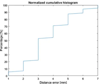
In Figure9, a normalized cumulative histogram is shown, where x-axis represents the distance error in millimetres, while they-axis represents the percentage of the experiments, for which the error was below the corresponding value on thex-axis. As it can be seen, in 87.67% of the performed experiments the tool was positioned at a distance under 5 mm from the marker centre. The greatest impact on the positioning accu-racy has the uncertainty in the estimation of thez-axis of the robot RF. The positioning error is proportional to the height difference between the marker placed on the robot’s end effector and the marker representing the object of interest. In these evaluation experiments, this height difference was approximately 200 mm, which means that the error inz-axis estimation of 1.43◦results in a positioning error of 5 mm.
5.3. Grasping experiments
In order to evaluate the applicability of the proposed grasp planning approach, a series of object grasping experiments were performed. Twelve sets of experi-ments were performed. Each set consisted of hand–eye calibration followed by five grasping operations. In each grasping operation, an object placed on the horizon-tal plane in the robot’s working region, as shown in Figure6, was detected in the scene, and its centroid, representing the target position for visual servoing, as well as tool rotation required for successful grasp are computed as described in Section4. The rotation angle of the considered gripper mounted on the robot arm is
Figure 9.Normalized cumulative histogram of tool positioning error.
Figure 10.The initial position of the gripper.
defined on the intervalq4∈[0,π]. Figure10represents
the initial position of the gripper, whenq4=0. Visual
servoing navigated the robot arm above the object of interest and grasping was performed. The object was finally moved to a target destination, which in this experiment was represented by a marker placed in the scene.
An experiment was considered successful if an object was properly detected, the robot arm was posi-tioned above the object, the gripper was correctly rotated and the object was grasped, lifted and moved to the target position. The results are shown in Table2. Out of 60 grasping experiments, 4 were unsuccessful due to the error in object recognition. Since object recognition is not the topic of this paper, failures in object recognition weren’t included in the reported statistics. Three grasping operations were unsuccess-ful due to the insufficient visual servoing precision. In these three experiments, the object wasn’t correctly
Table 2.Grasping experimental results.
Successful Unsuccessful
Number of experiments 53 3
Per cent 94.64 5.36
grasped and it slipped off the gripper. The rest of the experiments were successful.
6. Conclusion and future work
In this paper, a vision-guided robot manipulation sys-tem is described, which uses only visual feedback for positioning of the tool and grasping of simple objects, therefore making it suitable for low-cost systems with-out encoders. The described system is based on visual servoing, which uses a novel fast hand–eye calibra-tion method. A short execucalibra-tion time of the proposed method is of great importance when frequent recalibra-tion is needed. The reported experimental tests prove that the obtained positioning accuracy is suitable for object manipulation tasks where accuracy of 7 mm is sufficient. Grasping was successful in 95% of experi-ments.
The positioning accuracy considerably depends on the accuracy of the supporting plane estimation, where the positioning error increases linearly with the dis-tance between the marker and the tool. Hence, the posi-tioning accuracy could be improved by a robot design, which would reduce this distance. Furthermore, it was noticed that RGB and depth registration in images captured by the considered camera are not accurate. Since the methods considered in this paper use both RGB and depth information, and therefore depend on well-aligned images, incorrect registration represents a source of the inaccuracy in positioning. One solu-tion to this problem is to use a different RGB-D sen-sor with more accurate registration between the RGB and depth images, or a calibration algorithm which provides optimal registration parameters between the RGB and depth camera. In the future, a system could perform automatic recalibration each time when the camera changes its angle and point of view. Also, an extended Kalman filter for pose estimation may be included. Since few failures in object manipulation were recorded, a vision system can be used to recover the robot from failure. Failure detection and recov-ery strategies are also a possible topic of our future research.
Disclosure statement
No potential conflict of interest was reported by the authors.
Funding
This work has been fully supported by the Hrvatska Zaklada za Znanost (Croatian Science Foundation) under the project number IP-2014-09-3155.
ORCID
R. Cupec http://orcid.org/0000-0003-4451-7952
References
[1] International Federation of Robotics [Internet]. [cited 2018 Feb 13]. Available from:https://ifr.org/
[2] Kim HS, Min JK, Song JB. Multi-DOF counterbalance mechanism for low-cost, safe and easy-usable robot arm. In: 11th International Conference on Ubiqui-tous Robots and Ambient Intelligence (URAI); 2014. p. 185–188.
[3] Larouche BP, Zhu ZH.Autonomous robotic capture of non-cooperative target using visual servoing and motion predictive control. Auton Robots.2014;37(2):157–167. [4] Durović P, Grbić R, Cupec R, et al. Low cost robot arm
with visual guided positioning. In: MIPRO Proceedings; Rijeka; 2017. p. 1332–1337.
[5] Craig JJ. Introduction to robotics: mechanics and con-trol. 3rd ed. Upper Saddle River (NJ) Pearson Prentice Hall;2005.
[6] Van Delden S, Hardy F. Robotic eye-in-hand calibration in an uncalibrated environment. J Syst.2009;6(6):67–72. [7] Lippiello V, Siciliano B, Villani L. Eye-in-hand/eye-to-hand multi-camera visual servoing. In: 44th IEEE Con-ference on Decision and Control, 2005 and 2005 Euro-pean Control Conference, CDC-ECC’05; Seville, Spain. 2005. p. 5354–5359.
[8] Qiao Y, Liu QS, Liu GP. A new method of self-calibration of hand-eye systems based on active vision. In: The International Federation of Automatic Con-trol; Aug 24–29; Cape Town, South Africa; 2014. p. 9347–9352.
[9] Xu H, Wang Y, Chen W, et al. A self-calibration approach to hand-eye relation using a single point. In: International Conference on Information and Automa-tion, ICIA 2008; Zhangjiajie, China. 2008. p. 413–418. [10] Miseikis J, Glette K, Elle OJ, et al. Automatic
calibra-tion of a robot manipulator and multi 3d camera system; 2016. arXiv preprint arXiv:1601.01566.
[11] Heller J, Henrion D, Pajdla T. Hand-eye and robot-world calibration by global polynomial optimization. In: 2014 IEEE International Conference on Robotics and Automation (ICRA); Hong Kong, China. 2014. p. 3157–3164.
[12] Strobl KH, Hirzinger G. Optimal hand-eye calibra-tion. In: IEEE/RSJ International Conference on Intelli-gent Robots and Systems; Stockholm, Sweden. 2006. p. 4647–4653.
[13] Boby RA, Saha SK. Single image based camera cali-bration and pose estimation of the end-effector of a robot. In: IEEE International Conference on Robotics and Automation (ICRA); 2016. p. 2435–2440.
[14] Freeman RM, Julier SJ, Steed AJ. A method for pre-dicting marker tracking error. In: 6th IEEE and ACM International Symposium on Mixed and Augmented Reality, ISMAR 2007; Nara, Japan. 2007. p. 157–160. [15] Speth J, Morales A, Sanz PJ. Vision-based grasp
plan-ning of 3D objects by extending 2D contour based algo-rithms. In: IEEE/RSJ International Conference on Intel-ligent Robots and Systems, IROS 2008; Nice, France. 2008. p. 2240–2245.
[16] Lin C-C, Gonzalez P, Cheng M-Y, et al. Vision based object grasping of industrial manipulator. In: 2016 International Conference on Advanced Robotics and Intelligent Systems (ARIS); Taipei, Taiwan. 2016. p. 1–5.
[17] Xue Z, Dillmann R. Efficient grasp planning with reach-ability analysis. In: Liu H, Ding H, Xiong Z, Zhu X, edi-tor. Intelligent robotics and applications. ICIRA 2010; Berlin: Springer; 2010. (Lecture notes in computer sci-ence; 6424).
[18] Marton Z-C, Pangercic D, Blodow N, et al. General 3D modelling of novel objects from a single view. In: 2010 IEEE/RSJ International Conference on Intelligent Robots and Systems (IROS); Taipei, Taiwan. 2010. p. 3700–3705.
[19] Aldoma A, Tombari F, Di Stefano L, et al. A global hypothesis verification method for 3d object recogni-tion. In: European Conference on Computer Vision (ECCV); Florence, Italy. 2012.
[20] Papazov C, Burschka D. An efficient RANSAC for 3D object recognition in noisy and occluded scenes. In: Asian Conference on Computer Vision (ACCV), Part I; 2010. p. 135–148.
[21] Hinterstoisser S, Cagniart C, Ilic S, et al. Gradi-ent response maps for real-time detection of texture-less objects. IEEE Trans Pattern Anal Mach Intell. 2012;34(5):876–888.
[22] Mueller CA, Pathak K, Birk A. Object shape cate-gorization in RGBD images using hierarchical graph constellation models based on unsupervisedly learned shape parts described by a set of shape specificity levels. In: IEEE/RSJ International Conference on Intelligent Robots and Systems (IROS); Chicago (IL), USA; 2014. p. 3053–3060.
[23] Detry R, Ek CH, Madry M, et al. Learning a dictionary of prototypical grasp-predicting parts from grasping experience. In: 2014 IEEE International Conference on Robotics and Automation (ICRA); Hong Kong, China. 2014. p. 3157–3164.
[24] Twardon L, Ritter H. Interaction skills for a coat-check robot: identifying and handling the boundary compo-nents of clothes. In: IEEE International Conference on Robotics and Automation (ICRA); Seattle, Washington, USA. 2015. p. 3682–3688.
[25] Kragic D, Miller AT, Allen PK. Real-time tracking meets online grasp planning. In: IEEE International Conference on Robotics and Automation, Proceed-ings 2001 ICRA, Vol. 3; Seoul, Korea. 2001. p. 2460– 2465.
[26] Lopez-Damian E, Sidobre D, Alami R. Grasp planning for non-convex objects. In: International Symposium on Robotics, Vol. 36; Tokyo, Japan. 2005. p. 167.
[27] Simeon T, Laumond J-P, Lamiraux F. Move3d: a generic platform for motion planning. In: Proceedings of the 4th International Symposium on Assembly and Task Planning (ISATP’2001); Fukoka, Japan. 2001.
[28] Borst C, Fischer M, Hirzinger G. Calculating hand con-figurations for precision and pinch grasps. In: IEEE/RSJ International Conference on Intelligent Robots and Sys-tems, 2002. Vol. 2; Lausanne, Switzerland. 2002. p. 1553–1559.
[29] Miller AT, Allen PK. Graspit! a versatile simula-tor for robotic grasping. IEEE Robot Autom Mag. 2004;11(4):110–122.
[30] Fischler MA, Bolles RC. Random sample consensus: a paradigm for model fitting with applications to image analysis and automated cartography. Graph Image Pro-cess.1981;24(6):381–395.
[31] Serdar K, Bingul Z. Robot kinematics: forward and inverse kinematics. In: Cubero S, editor. Industrial robotics: theory, modelling and control; 2006. ISBN: 3-86611-285-8, InTech.
[32] Cupec R, Filko D, Nyarko EK. Segmentation of depth images into objects based on local and global convexity. In: European Conference on Mobile Robotics (ECMR); Paris; 2017.
[33] Cupec R, Nyarko EK, Filko D, et al. Global localization based on 3d planar surface segments. In: Proceedings of the Croatian Computer Vision Workshop, (CCVW) 2013; Zagreb; 2013. p. 31–36.
[34] Orbbec Astra [Internet]. [cited 2017 Nov 13]. Available from:https://orbbec3d.com/.
[35] ArUco: a minimal library for augmented reality applica-tions based on OpenCV [Internet]. [cited 2017 Novem-ber 13]. Available from: https://www.uco.es/investiga/ grupos/ava/node/26.
[36] Kaehler A, Bradski G. Learning OpenCV 3. Sebastopol (CA): O’Reilly Media;2016.
Appendices
Appendix 1. Marker positioning using an RGB-D camera
The following steps explain obtaining the 3D position of the marker.
Step 1:The RGB-D camera captures an image.
Step 2:The centre of the marker is identified in the RGB image and itsx-,y- andz-coordinates are computed using appropriate computer vision software.
Step 3:The coordinates of the marker centre in the depth image are determined using its coordinates in the RGB image.
Step 4:In order to reduce the impact of the measurement noise, the average depth of a square neighbourhood around the marker centre is computed. A newz-coordinate of the marker centre w.r.t. the camera is obtained.
Step 5.Scaling factorsis computed by Equation (2).
Step 6.The final 3D position of the marker is computed by multiplying each coordinate,x,yandz, computed in Step 2 with scaling factors.
Appendix 2. Hand–eye calibration method
The following steps represent the proposed simple, two-step hand–eye calibration algorithm.
Step 1: Get a depth image from the camera, where each image point is assigned its 3D coordinates in the camera’s RF.
Step 2:Compute the parameters of the dominant plane in the scene using a standard RANSAC procedure [30]. Define thez-axis of the robot RF w.r.t. the camera RF as the unit vector perpendicular to this plane.
Step 3.In the captured image, search for the marker on the end effector. The centre of the marker position represents pointCpM(0).
Step 4.Perform a rotation with the shoulder joint for a known angle differenceq2, obtained by Equation (6), in a
positive direction. The camera captures an image. The new marker centre position represents pointCpM(1).
Step 5.Compute the position of the origin of the robot RF Ct