GE Healthcare
Technical Publications
Direction 2067192-001
Revision 4
Universal Viewer* Web Client Version 5.0 SP5
DICOM CONFORMANCE STATEMENT
* Trademark of General Electric Company
Copyright
2014 by General Electric Co.
Acknowledgments
Prepared by Mark Niggemann.
Confidentiality and Proprietary Rights
This document is the confidential property of GE Healthcare, a division of General Electric Company (“GE Healthcare”). No part of this document may be reproduced in any form, by photostat, microfilm, xerography, or any other means, or incorporated into any information retrieval system, electronic or mechanical, without the written permission of GE Healthcare. Inquiries regarding copying and/or using the materials contained in this document outside of the limited scope described herein should be addressed to the e-mail address listed above. GE Healthcare reminds you that there may be legal, ethical, and moral obligations for medical care providers to protect sensitive patient information when dealing with vendors such as GE Healthcare. You should obtain explicit written consent from both the patient and GE Healthcare before you disclose sensitive patient information to GE Healthcare.
Limitations and Conditions of Use
This document is the confidential property of GE Healthcare and is furnished to you, a current GE Healthcare customer, pursuant to a non-disclosure agreement (“NDA”) between you and GE Healthcare. If you are not (i) a current GE Healthcare customer, and (ii) subject to an NDA with GE Healthcare, you are not authorized to access this document.
The information contained herein is confidential and should not be used, disclosed, or duplicated for any purpose other than developing information system plans within GE Healthcare customer organizations. Duplication and/or distribution of this document beyond GE Healthcare customer organization information systems and management executives are not allowed without express written consent from GE Healthcare.
Trademarks
GE, the GE Monogram, Centricity and imagination at work are trademarks of General Electric Company. All other product names and logos are trademarks or registered trademarks of their respective companies.
Disclaimers
Any information related to clinical functionality is intended for clinical professionals. Clinical professionals are expected to know the medical procedures, practices and terminology required to monitor patients. Operation of the product should neither circumvent nor take precedence over required patient care, nor should it impede the human intervention of attending nurses, physicians or other medical personnel in a manner that would have a negative impact on patient health.
General Electric Company reserves the right to make changes in specifications and features shown herein, or discontinue the products described at any time without notice or obligation. This does not constitute a representation or warranty or documentation regarding the product or service featured. All illustrations or examples are provided for informational or reference purposes and/or as fictional examples only. Your product features and configuration may be different than those shown. Contact your GE Representative for the most current information.
GE Healthcare
540 West Northwest Highway Barrington, IL 60010 U.S.A.
Revision History
Revision Date Author Description
1 August 10, 2012 Eric Feingold Initial Version for IR2.
2 October 18, 2012 Eric Feingold Updated for IR3 with new support for RTSS and Breast Tomosynthesis 3 August 13, 2013 Mark Niggemann Updated revision info, specific to Universal Viewer product and added reference to Volume Viewer DCS.
4 August 19, 2014 Mark Niggemann
Updated conformance to be standalone reference for display abilities without regard to backend.
Added Basic Text SR as a supported displayable object. Expanded sections to cover generation of GSPS and KOS objects and incorporated content from the PACS-IW server side DCS relevant to each.
Additional updates made as result of Interop CoE feedback.
CONFORMANCE STATEMENT OVERVIEW
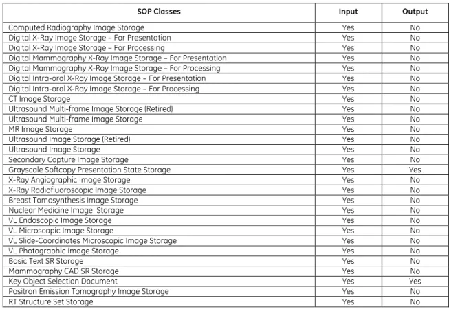
Table 0.1 provides an overview of the DICOM objects supported by Universal Viewer web client..
Note: The Universal Viewer web client is a viewing application that may be deployed with Centricity
PACS or Centricity PACS-IW backend application servers. Universal Viewer does not directly use DICOM network features to communicate with any external application. However it does display DICOM information objects from the backend application servers. It also has the ability to generate Grayscale Presentation States and Key Object Selection objects and store them in the backend application servers which manages them.
Table 0.1 Supported SOP Classes
SOP Classes Input Output
Computed Radiography Image Storage Yes No Digital X-Ray Image Storage – For Presentation Yes No Digital X-Ray Image Storage – For Processing Yes No Digital Mammography X-Ray Image Storage – For Presentation Yes No Digital Mammography X-Ray Image Storage – For Processing Yes No Digital Intra-oral X-Ray Image Storage – For Presentation Yes No Digital Intra-oral X-Ray Image Storage – For Processing Yes No
CT Image Storage Yes No
Ultrasound Multi-frame Image Storage (Retired) Yes No Ultrasound Multi-frame Image Storage Yes No
MR Image Storage Yes No
Ultrasound Image Storage (Retired) Yes No
Ultrasound Image Storage Yes No
Secondary Capture Image Storage Yes No Grayscale Softcopy Presentation State Storage Yes Yes X-Ray Angiographic Image Storage Yes No X-Ray Radiofluoroscopic Image Storage Yes No Breast Tomosynthesis Image Storage Yes No Nuclear Medicine Image Storage Yes No
VL Endoscopic Image Storage Yes No
VL Microscopic Image Storage Yes No
VL Slide-Coordinates Microscopic Image Storage Yes No
VL Photographic Image Storage Yes No
Basic Text SR Storage Yes No
Mammography CAD SR Storage Yes No
Key Object Selection Document Yes Yes
Positron Emission Tomography Image Storage Yes No
TABLE OF CONTENTS
1.
INTRODUCTION ... 1
1.1
OVERVIEW ... 1
1.2
OVERALL DICOMCONFORMANCE STATEMENT DOCUMENT STRUCTURE ... 2
1.3
INTENDED AUDIENCE ... 3
1.4
SCOPE AND FIELD OF APPLICATION ... 3
1.5
IMPORTANT REMARKS ... 3
1.6
REFERENCES ... 4
1.7
DEFINITIONS ... 4
1.8
SYMBOLS AND ABBREVIATIONS ... 6
2.
NETWORK CONFORMANCE STATEMENT ... 8
2.1
INTRODUCTION ... 8
2.2
IMPLEMENTATION MODEL ... 9
2.2.1
Application Data Flow Diagrams ... 9
2.2.2
Functional Definition of AE’s ... 12
2.2.3
Sequencing of Real-World Activities ... 12
2.3
AESPECIFICATIONS ... 13
2.4
COMMUNICATION PROFILES ... 13
2.5
EXTENSIONS /SPECIALIZATIONS /PRIVATIZATIONS ... 13
2.5.1
Window/Level Computation ... 13
2.6
CONFIGURATION ... 13
2.7
SUPPORT OF EXTENDED CHARACTER SETS ... 13
2.8
CODES AND CONTROLLED TERMINOLOGY ... 14
3.
GRAYSCALE SOFTCOPY PRESENTATION STATE IOD IMPLEMENTATION ... 15
3.1
MAPPING OF DICOMENTITIES ... 15
3.2
IODMODULE TABLE ... 15
3.3
INFORMATION MODULE DEFINITIONS ... 16
3.3.1
Patient Entity Modules ... 16
3.3.2
Study Entity Modules ... 17
3.3.3
Series Entity Modules ... 17
3.3.4
Equipment Entity Modules ... 17
3.3.5
Presentation State Entity Modules ... 18
3.4
PRIVATE DATA ATTRIBUTES ... 21
3.4.1
Private Group GEIIS_IW ... 22
3.4.2
Private Group GEIIS_RA1000 ... 23
4.
KEY OBJECT SELECTION IOD IMPLEMENTATION ... 24
4.1
INTRODUCTION ... 24
4.2
MAPPING OF DICOMENTITIES ... 24
4.3
IODMODULE TABLE ... 24
4.4
INFORMATION MODULE DEFINITIONS ... 25
4.4.1
Series Entity Modules ... 25
4.4.2
Document Entity Modules ... 25
4.5
PRIVATEDATAATTRIBUTES ... 28
1.
INTRODUCTION
1.1
O
VERVIEWThis DICOM Conformance Statement is divided into Sections as described below:
Section 1 (Introduction), which describes the overall structure, intent, and references for this
Conformance Statement
Section 2 (Network Conformance Statement), which specifies the GEHC equipment compliance to the
DICOM requirements for the implementation of Networking features.
Section 3 (Grayscale Presentation State IOD), which specifies the GEHC equipment compliance to
DICOM requirements for the implementation of a Grayscale Presentation State Information Object.
Section 4 (Key Object Selection IOD), which specifies the GEHC equipment compliance to DICOM
1.2
O
VERALLDICOM
C
ONFORMANCES
TATEMENTD
OCUMENTS
TRUCTUREThe Documentation Structure of the GEHC DICOM Conformance Statements is shown in the Illustration below. CT Advantage Conformance Statement Direction: MR Advantage Conformance Statement Direction: Universal Viewer web client Conformance Statement Direction: 2067192 ... Conformance Statement Direction: ... DICOM Part 4 DICOM Part 3 DICOM Part 2 DICOM Part 1 DICOM Part 16
GEHC DICOM Conformance Statements
APPLICATION ENTITY SPECIFICATION
(SERVICE CLASSES, INFORMATION OBJECTS, MESSAGE EXCHANGES, ETC.)
DICOM STANDARD
Product
Implementation:
Standard
Specification:
@
http://www.ge.com/DICOM
This document specifies the DICOM implementation. It is entitled: Universal Viewer Web Client Version 5.0 SP5
DICOM Conformance Statement Direction 2067192-001
This DICOM Conformance Statement documents the DICOM Conformance Statement and Technical Specification required to interoperate with the GEHC network interface.
The GEHC Conformance Statement, contained in this document, also specifies the Lower Layer communications which it supports (e.g., TCP/IP). However, the Technical Specifications are defined in the DICOM Part 8 standard.
For more information regarding DICOM, copies of the Standard may be obtained on the Internet at http://medical.nema.org. Comments on the Standard may be addressed to:
DICOM Secretariat NEMA 1300 N. 17th Street, Suite 1752 Rosslyn, VA 22209 USA Phone: +1.703.841.3200
1.3
I
NTENDEDA
UDIENCEThe reader of this document is concerned with software design and/or system integration issues. It is assumed that the reader of this document is familiar with the DICOM 3.0 standard and with the terminology and concepts that are used in this standard.
1.4
S
COPE ANDF
IELD OFA
PPLICATIONIt is the intent of this document to provide an unambiguous specification for GEHC implementations. This specification, called a Conformance Statement, includes a DICOM Conformance Statement and is necessary to ensure proper processing and interpretation of GEHC medical data exchanged using DICOM. The GEHC Conformance Statements are available to the public.
The reader of this DICOM Conformance Statement should be aware that different GEHC devices are capable of using different Information Object Definitions. For example, a GEHC CT Scanner may send images using the CT Information Object, MR Information Object, Secondary Capture Object, etc. Included in this DICOM Conformance Statement are the Module Definitions which define all data elements used by this GEHC implementation. If the user encounters unspecified private data elements while parsing a GEHC Data Set, the user is well advised to ignore those data elements (per the DICOM standard). Unspecified private data element information is subject to change without notice. If, however, the device is acting as a "full fidelity storage device", it should retain and re-transmit all of the private data elements which are sent by GEHC devices.
1.5
I
MPORTANTR
EMARKSThe Universal Viewer web client conforms to NEMA PS3(2011) DICOM standards.
The use of these DICOM Conformance Statements, in conjunction with the DICOM Standards, is intended to facilitate communication with GE imaging equipment. However, by itself, it is not
sufficient to ensure that inter-operation will be successful. The user (or user's agent) needs to
Integration - The integration of any device into an overall system of interconnected devices goes beyond the scope of standards (DICOM v3.0), and of this introduction and associated DICOM Conformance Statements when interoperability with non-GE equipment is desired. The responsibility to analyze the applications requirements and to design a solution that integrates GE imaging equipment with non–GE systems is the user's responsibility and should not be underestimated. The user is strongly advised to ensure that such an integration analysis is correctly performed.
Validation - Testing the complete range of possible interactions between any GE device and non–GE
devices, before the connection is declared operational, should not be overlooked. Therefore, the user
should ensure that any non–GE provider accepts full responsibility for all validation required for their connection with GE devices. This includes the accuracy of the image data once it has crossed the interface between the GE imaging equipment and the non–GE device and the stability of the image data for the intended applications.
Such a validation is required before any clinical use (diagnosis and/or treatment) is performed. It applies when images acquired on GE imaging equipment are processed/displayed on a non-GE device, as well as when images acquired on non-GE equipment is processed/displayed on a GE console or workstation.
Future Evolution - GE understands that the DICOM Standard will evolve to meet the user's growing
requirements. GE is actively involved in the development of the DICOM Standard. DICOM will incorporate new features and technologies and GE may follow the evolution of the Standard. The GEHC protocol is based on DICOM as specified in each DICOM Conformance Statement. Evolution of the Standard may require changes to devices which have implemented DICOM. In addition, GE reserves the right to discontinue or make changes to the support of communications features (on
its products) described by these DICOM Conformance Statements. The user should ensure that any
non–GE provider, which connects with GE devices, also plans for the future evolution of the DICOM Standard. Failure to do so will likely result in the loss of function and/or connectivity as the DICOM Standard changes and GE Products are enhanced to support these changes.
Interaction - It is the sole responsibility of the non–GE provider to ensure that communication with
the interfaced equipment does not cause degradation of GE imaging equipment performance and/or function.
1.6
R
EFERENCESNEMA PS3(2011) Digital Imaging and Communications in Medicine (DICOM) Standard, available free at http://medical.nema.org/
Centricity PACS 4.0 DICOM Conformance Statement, DOC1145900
Centricity PACS-IW 5.0 Server DICOM Conformance Statement, DOC1193612 Centricity Enterprise Archive 4.0 DICOM Conformance Statement, DOC0708777
1.7
D
EFINITIONSInformal definitions are provided for the following terms used in this Conformance Statement. The DICOM Standard is the authoritative source for formal definitons of these terms.
Abstract Syntax – the information agreed to be exchanged between applications, generally equivalent
to a Service/Object Pair (SOP) Class. Examples: Verification SOP Class, Modality Worklist Information Model Find SOP Class, Computed Radiography Image Storage SOP Class.
Application Entity (AE) – an end point of a DICOM information exchange, including the DICOM network
or media interface software; i.e., the software that sends or receives DICOM information objects or messages. A single device may have multiple Application Entities.
Application Entity Title – the externally known name of an Application Entity, used to identify a DICOM application to other DICOM applications on the network.
Application Context – the specification of the type of communication used between Application
Entities. Example: DICOM network protocol.
Association – a network communication channel set up between Application Entities.
Attribute – a unit of information in an object definition; a data element identified by a tag. The
information may be a complex data structure (Sequence), itself composed of lower level data elements. Examples: Patient ID (0010,0020), Accession Number (0008,0050), Photometric Interpretation (0028,0004), Procedure Code Sequence (0008,1032).
Information Object Definition (IOD) – the specified set of Attributes that comprise a type of data
object; does not represent a specific instance of the data object, but rather a class of similar data objects that have the same properties. The Attributes may be specified as Mandatory (Type 1), Required but possibly unknown (Type 2), or Optional (Type 3), and there may be conditions associated with the use of an Attribute (Types 1C and 2C). Examples: MR Image IOD, CT Image IOD, Print Job IOD.
Joint Photographic Experts Group (JPEG) – a set of standardized image compression techniques,
available for use by DICOM applications.
Media Application Profile – the specification of DICOM information objects and encoding exchanged
on removable media (e.g., CDs)
Module – a set of Attributes within an Information Object Definition that are logically related to each
other. Example: Patient Module includes Patient Name, Patient ID, Patient Birth Date, and Patient Sex.
Negotiation – first phase of Association establishment that allows Application Entities to agree on the
types of data to be exchanged and how that data will be encoded.
Presentation Context – the set of DICOM network services used over an Association, as negotiated
between Application Entities; includes Abstract Syntaxes and Transfer Syntaxes.
Protocol Data Unit (PDU) – a packet (piece) of a DICOM message sent across the network. Devices
must specify the maximum size packet they can receive for DICOM messages.
Security Profile – a set of mechanisms, such as encryption, user authentication, or digital signatures,
used by an Application Entity to ensure confidentiality, integrity, and/or availability of exchanged DICOM data
Service Class Provider (SCP) – role of an Application Entity that provides a DICOM network service;
typically, a server that performs operations requested by another Application Entity (Service Class User). Examples: Picture Archiving and Communication System (image storage SCP, and image query/retrieve SCP), Radiology Information System (modality worklist SCP).
Service Class User (SCU) – role of an Application Entity that uses a DICOM network service; typically, a
client. Examples: imaging modality (image storage SCU, and modality worklist SCU), imaging workstation (image query/retrieve SCU)
Service/Object Pair (SOP) Class – the specification of the network or media transfer (service) of a
particular type of data (object); the fundamental unit of DICOM interoperability specification. Examples: Ultrasound Image Storage Service, Basic Grayscale Print Management.
Service/Object Pair (SOP) Instance – an information object; a specific occurrence of information
exchanged in a SOP Class. Examples: a specific x-ray image.
Tag – a 32-bit identifier for a data element, represented as a pair of four digit hexadecimal numbers, the “group” and the “element”. If the “group” number is odd, the tag is for a private
(manufacturer-specific) data element. Examples: (0010,0020) [Patient ID], (07FE,0010) [Pixel Data], (0019,0210) [private data element]
Transfer Syntax – the encoding used for exchange of DICOM information objects and messages.
Examples: JPEG compressed (images), little endian explicit value representation.
Unique Identifier (UID) – a globally unique “dotted decimal” string that identifies a specific object or a
class of objects; an ISO-8824 Object Identifier. Examples: Study Instance UID, SOP Class UID, SOP Instance UID.
Value Representation (VR) – the format type of an individual DICOM data element, such as text, an
integer, a person’s name, or a code. DICOM information objects can be transmitted with either explicit identification of the type of each data element (Explicit VR), or without explicit identification (Implicit VR); with Implicit VR, the receiving application must use a DICOM data dictionary to look up the format of each data element.
1.8
S
YMBOLS ANDA
BBREVIATIONSTerm Description
AE Application Entity AET Application Entity Title CAD Computer Aided Detection CD-R Compact Disk Recordable CR Computerized radiography CSE Customer Service Engineer CT Computerized Tomography DHCP Dynamic Host Configuration Protocol
DICOM Digital Imaging and Communications in Medicine DX Digital X-ray
FSC File-Set Creator FSU File-Set Updater FSR File-Set Reader
GSDF Grayscale Standard Display Function GSPS Grayscale Softcopy Presentation State HIS Hospital Information System HL7 Health Level 7 Standard IE Information Entity
IHE Integrating the Healthcare Enterprise IO Intra-oral X-ray
IOD Information Object Definition ISO International Standards Organization JPEG Joint Photographic Experts Group LUT Look-up Table
MG Mammography (X-ray) MR Magnetic Resonance NM Nuclear Medicine O Optional (Key Attribute) OP Ophthalmic Photography OSI Open Systems Interconnection
PACS Picture Archiving and Communication System PET Positron Emission Tomography
PDU Protocol Data Unit R Required (Key Attribute) RF Radiofluoroscopy
RIS Radiology Information System
RT Radiotherapy
SC Secondary Capture SCP Service Class Provider SCU Service Class User SOP Service-Object Pair
Term Description SR Structured Reporting
TCP/IP Transmission Control Protocol/Internet Protocol UID Unique Identifier
U Unique (Key Attribute)
UL Upper Layer US Ultrasound VM Value Multiplicity VL Visible Light VR Value Representation XA X-ray Angiography
2.
NETWORK CONFORMANCE
STATEMENT
2.1
I
NTRODUCTIONThis section of the DICOM Conformance Statement specifies the Universal Viewer web client compliance to DICOM requirements for networking features.
Note: The Universal Viewer web client does not directly communicate using DICOM networking and
data encoding features with external equipment.
Universal Viewer displays DICOM information objects retrieved from supported backend server application systems using proprietary communications. Universal Viewer currently supports either:
• Centricity PACS version 4.0 SP1 or later • Centricity PACS-IW Server version 5.0 or later.
Any DICOM related real world activities initiated from Universal Viewer are communicated to the backend server application where respective host services are utilized to carry out DICOM functions such as DICOM query/retrieve and DICOM send.
Note: Universal Viewer may be capable of displaying SOP classes that are not supported for storage
by the respective backend server. Please refer to the DICOM Conformance Statement of the appropriate backend application server for more information.
Although the hosted backed server may support additional SOP Classes, Universal Viewer clients are only able to interpret objects that meet the conditions in the table below.
TABLE 2-1 DISPLAYABLE SOP CLASSES
SOP Class Name SOP Class UID
Computed Radiography Image Storage 1.2.840.10008.5.1.4.1.1.1 Digital X-Ray Image Storage - For Presentation 1.2.840.10008.5.1.4.1.1.1.1 Digital X-Ray Image Storage - For Processing 1.2.840.10008.5.1.4.1.1.1.1.1 Digital Mammography Image Storage - For Presentation 1.2.840.10008.5.1.4.1.1.1.2 Digital Mammography Image Storage - For Processing 1.2.840.10008.5.1.4.1.1.1.2.1 Digital Intro-oral X-Ray Image Storage - For Presentation 1.2.840.10008.5.1.4.1.1.1.3 Digital Intra-oral X-Ray Image Storage - For Processing 1.2.840.10008.5.1.4.1.1.1.3.1 CT Image Storage 1.2.840.10008.5.1.4.1.1.2 Ultrasound Multi-Frame Image Storage (Retired) 1.2.840.10008.5.1.4.1.1.3 Ultrasound Multi-frame Image Storage 1.2.840.10008.5.1.4.1.1.3.1 MR Image Storage 1.2.840.10008.5.1.4.1.1.4 Ultrasound Image Storage (Retired) 1.2.840.10008.5.1.4.1.1.6 Ultrasound Image Storage 1.2.840.10008.5.1.4.1.1.6.1 Secondary Capture Image Storage 1.2.840.10008.5.1.4.1.1.7 Grayscale Softcopy Presentation State Storage 1.2.840.10008.5.1.4.1.1.11.1 X-Ray Angiographic Image Storage 1.2.840.10008.5.1.4.1.1.12.1 X-Ray Radiofluoroscopic Image Storage 1.2.840.10008.5.1.4.1.1.12.2
SOP Class Name SOP Class UID Breast Tomosynthesis Image Storage 1.2.840.10008.5.1.4.1.1.13.1.3 Nuclear Medicine Image Storage 1.2.840.10008.5.1.4.1.1.20 VL Endoscopic Image Storage 1.2.840.10008.5.1.4.1.1.77.1.1 VL Microscopic Image Storage 1.2.840.10008.5.1.4.1.1.77.1.2 VL Slide-Coordinates Microscopic Image Storage 1.2.840.10008.5.1.4.1.1.77.1.3 VL Photographic Image Storage 1.2.840.10008.5.1.4.1.1.77.1.4 Basic Text SR Storage 1.2.840.10008.5.1.4.1.1.88.11 Mammography CAD SR Storage 1.2.840.10008.5.1.4.1.1.88.50 Key Object Selection Storage 1.2.840.10008.5.1.4.1.1.88.59 Positron Emission Tomography Image Storage 1.2.840.10008.5.1.4.1.1.128 RT Structure Set Storage 1.2.840.10008.5.1.4.1.1.481.3
TABLE 2-2
DISPLAYABLE PHOTOMETRIC INTERPRETATION SUPPORTED Photometric
Interpretation (0028,0004) The image SOP Instance must contain one of the following Photometric Interpretation values: MONOCHROME1
MONOCHROME2 RGB
PALETTE COLOR
Universal Viewer is capable of generating the following SOP classes and store them in any of the supported backend servers utilizing an internal service API.
TABLE 2-3 GENERATED SOP CLASSES
SOP Class Name SOP Class UID
Grayscale Softcopy Presentation State Storage 1.2.840.10008.5.1.4.1.1.11.1 Key Object Selection Storage 1.2.840.10008.5.1.4.1.1.88.59
2.2
I
MPLEMENTATIONM
ODEL2.2.1
Application Data Flow Diagrams
2.2.1.1 ST O R A G E AE FO R SOP IN S T A N C E DI S P L A YThe Storage AE implements the SCP roles of the DICOM Storage SOP classes for storing DICOM Storage SOP instances.
Note: The Storage AE services are provided by their configured backend application server. As such,
Universal Viewer does not directly handle DICOM network features related to Storage AE. It communicates to the backend application server using an internal service API.
Both the Centricity PACS and Centricity PACS-IW backend application servers support a conceptual Storage AE that may be named differently in their conformance statements.
Please refer to the DICOM Conformance Statement of the appropriate backend application server for more information.
FIGURE 2-1
DATA FLOW DIAGRAM OF STORAGE AE FOR SOP INSTANCE DISPLAY
Backend Application Server DICOM Standard Interface Store Received SOP Instances Remote AE Send SOP Instances Storage AE SCP Universal Viewer Render SOP Instances for Display UV Servlet Interface 2.2.1.2 SE N D AE F O R SOP IN S T A N C E TR A N F E R T O RE M O T E AE
The Send AE implements the SCU roles of the DICOM Storage SOP classes for sending DICOM Storage SOP instances to a remote AE.
Note: The Send AE services are provided by their configured backend application server. As such,
Universal Viewer does not directly initiate DICOM network features related to Send AE. It communicates to the backend application server using an internal service API.
At this time, only the Centricity PACS backend application server provides the Send AE service. Please refer to the Centricity PACS DICOM Conformance Statement for more information.
FIGURE 2-2
DATA FLOW DIAGRAM OF SEND AE FUNCTIONALITY
Backend Application Server DICOM Standard Interface Send AE SCU Remote AE Stores SOP Instances Send SOP Instances to Remote AE Universal Viewer UV Servlet Interface 2.2.1.3 QU E R Y/RE T R I E V E AE FU N C T I O N A L I T Y
Note: The Query/Retrieve AE services are provided by the configured backend application server.
Universal Viewer communicates to the backend application server using an host service API and thus does not directly initiate DICOM network features related to Query/Retrieve.
Both the Centricity PACS and Centricity PACS-IW backend application servers support Query/Retrieve AE.
Please refer to the DICOM Conformance Statement of the appropriate backend application server for more information.
FIGURE 2-3
DATA FLOW DIAGRAM OF QUERY/RETRIEVE AE FUNCTIONALITY
Backend Application Server DICOM Standard Interface Q/R AE SCU Remote AE Processes Query Initiate DICOM Query Store Received SOP Instances Remote AE Processes Retrieve Remote AE Moves Retrieved SOP Instance Initiate DICOM Retrieve Storage AE SCP Universal Viewer Render SOP Instances for Display UV Servlet Interface
2.2.2
Functional Definition of AE’s
Not Applicable.Note: Universal Viewer does not directly initiate or accept DICOM associations regardless of the
backend server configuration.
Please refer to the DICOM conformance statement of the appropriate backend application server for more information.
2.2.3
Sequencing of Real-World Activities
2.2.3.1 RE A L-WO R L D AC T I V I T Y – VI E W I N G A DICOM OB J E C TThe user may load any supported DICOM object into the Universal Viewer web client for viewing. 2.2.3.2 RE A L WO R L D AC T I V I T Y – CR E A T I O N O F GR A Y S C A L E PR E S E N T A T I O N ST A T E S
The user may create Grayscale Presentation States in the Universal Viewer web client and save the results in the configured backend server using direct access services.
2.2.3.3 RE A L WO R L D AC T I V I T Y – CR E A T I O N O F KE Y OB J E C T SE L E C T I O N
The user may create Key Object Selection documents in the Universal Viewer web client and save the results in the configured backend server using direct access services.
2.3
AE
S
PECIFICATIONSNot Applicable.
Note: Universal Viewer does not directly initiate or accept DICOM associations regardless of the
backend server configuration.
Please refer to the DICOM conformance statement of the appropriate backend application server for more information.
2.4
C
OMMUNICATIONP
ROFILESNot Applicable.
Note: Universal Viewer does not directly initiate or accept DICOM associations regardless of the
backend server configuration.
Please refer to the DICOM conformance statement of the appropriate backend application server for more information.
2.5
E
XTENSIONS/
S
PECIALIZATIONS/
P
RIVATIZATIONS2.5.1
Window/Level Computation
It is expected that optimal Window Center and Width values are specified in the DICOM Object Objects if they have greater than 8 bits of data stored per sample. If optimal Window Center and Width values are not provided, then Universal Viewer is capable of estimating values using histogram analysis.
2.6
C
ONFIGURATIONNot Applicable.
Note: Universal Viewer does not directly initiate or accept DICOM associations regardless of the
backend server configuration.
Please refer to the DICOM conformance statement of the appropriate backend application server for more information.
2.7
S
UPPORT OFE
XTENDEDC
HARACTERS
ETSThe Universal Viewer is configurable with a single single-byte or multi-byte extended character set, depending on the language selected during installation of the system. The following extended Character Sets are supported:
TABLE 2-3
Extended Character Set Support Encoding DICOM Term in Specific Character Set
(0008,0005) Supported Languages ASCII Attribute is not present (ISO IR-6) English
Latin-1 ISO IR-100 English, Faeroese, Finnish, French, German, Italian, Portuguese, Spanish, Latin-2 ISO IR-101 English, Polish, Hungarian.
Encoding DICOM Term in Specific Character Set
(0008,0005) Supported Languages Latin/Cyrillic ISO IR-144 English, Russian
Latin/Hebrew ISO IR-138 English, Hebrew
JIS X 0201 ISO IR-13 English, Japanese (in Katakana alphabet). Limited use as Japanese encoding does not support hieroglyphic alphabet
JIS X 0208 ISO 2022 IR-87 English, Japanese Kanji (hieroglyphic) – uses escape sequences to switch between ASCII (single byte) and Japanese (two-byte per character) KS X 1001 ISO 2022 IR-149 English, Korean – uses escape
sequences to switch between ASCII (single byte) and Korean (two-byte per character)
GB18030 GB18030 English, Simplified Chinese
While the backend servers may support additional character sets, the Centricity Universal Viewer will display in the user interface only characters specified as within ISO IR-6 (ASCII) or the configured extended character set.
The user interface will allow the user to enter characters from the console keyboard that are within ASCII or the configured extended character set.
Whether character sets are displayed correctly depends on the characteristics of the backend system, the validity of the DICOM header contents, and the presence of appropriate fonts on the client system.
2.8
C
ODES ANDC
ONTROLLEDT
ERMINOLOGYThe product uses no coded terminology. Universal Viewer does not directly parse DICOM SOP instances regardless of the backend server configuration.
Please refer to the DICOM conformance statement of the appropriate backend application server for more information.
3.
GRAYSCALE SOFTCOPY P
RESENTATION STATE
IOD IMPLE
MENTATION
This section specifies the use of the DICOM Grayscale Softcopy Presentation State IOD to represent the information included in GSPSs produced by the Universal Viewer implementation. Corresponding attributes are conveyed using the module construct.
Universal Viewer can create Grayscale Presentation State SOP Instances explicitly or they may be created when a user selects to export the internal presentation state of a study, or internal print pages (sets of key images). One or more objects may be created to represent content of the internal presentation state. If more than one GSPS object is created, all of them are created with the same values of Presentation Label, Description, Author, Creation Date and Time.
The Presentation Label and Description are entered by the user at the time of the export of the presentation state. If GSPS objects are created as part of the export the key image set, the Label and description are set automatically.
The product supports calibration of the monitors used for user creation of presentation states to the Grayscale Display Function Standard of DICOM. The monitors shall be calibrated according to their manufacturers’ recommendations and instructions.
3.1
M
APPINGO
FDICOM
E
NTITIESUniversal Viewer maps DICOM Information Entities to local information entities in the product’s database and user interface.
Table 3-1
Mapping of DICOM Entities to Local Entities DICOM IE Local Entity Patient Patient
Study Study
Series Series
Presentation State Presentation State
3.2
IOD
M
ODULET
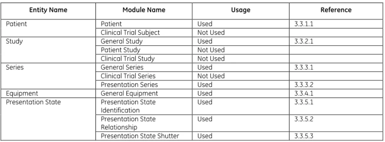
ABLEThe Grayscale Softcopy Presentation State Information Object Definition comprises the modules of the following table, plus Standard Extended and Private attributes. Standard Extended and Private attributes are described in Section 4.5.
Table 3-2 GSPS IOD MODULES
Entity Name Module Name Usage Reference
Patient Patient Used 3.3.1.1
Clinical Trial Subject Not Used
Study General Study Used 3.3.2.1 Patient Study Not Used
Clinical Trial Study Not Used
Series General Series Used 3.3.3.1 Clinical Trial Series Not Used
Presentation Series Used 3.3.3.2 Equipment General Equipment Used 3.3.4.1 Presentation State Presentation State
Identification Used 3.3.5.1 Presentation State
Relationship Used 3.3.5.2 Presentation State Shutter Used 3.3.5.3
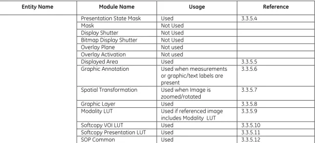
Entity Name Module Name Usage Reference Presentation State Mask Used 3.3.5.4
Mask Not Used Display Shutter Not Used Bitmap Display Shutter Not Used Overlay Plane Not used Overlay Activation Not used
Displayed Area Used 3.3.5.5 Graphic Annotation Used when measurements
or graphic/text labels are present
3.3.5.6 Spatial Transformation Used when Image is
zoomed/rotated 3.3.5.7 Graphic Layer Used 3.3.5.8 Modality LUT Used if referenced image
includes Modality LUT 3.3.5.9 Softcopy VOI LUT Used 3.3.5.10 Softcopy Presentation LUT Used 3.3.5.11 SOP Common Used 3.3.5.12
3.3
I
NFORMATIONM
ODULED
EFINITIONSPlease refer to DICOM Part 3 (Information Object Definitions) for a description of each of the entities, modules, and attributes contained within the GSPS Information Object.
The following modules are included to convey Enumerated Values, Defined Terms, and Optional Attributes supported. Type 1 & Type 2 Attributes are also included for completeness and to define what values they may take and where these values are obtained from when generating the instance. It should be noted that they are the same ones as defined in the DICOM Standard Part 3 (Information Object Definitions). Also note that Attributes not present in tables are not supported.
3.3.1
Patient Entity Modules
3.3.1.1 PA T I E N T MO D U L ETable 3-3
PATIENT MODULE ATTRIBUTES
Attribute Name Tag Type Attribute Description Patient's Name (0010,0010) 2 Taken from the images of the study Patient ID (0010,0020) 2 Taken from images of the study Issuer of Patient ID (0010,0021) 3 Not Used
Patient's Birth Date (0010,0030) 2 Taken from images of the study Patient's Sex (0010,0040) 2 Taken from images of the study Referenced Patient Sequence (0008,1120) 3 Not Used
Patient's Birth Time (0010,0032) 3 Not Used Other Patient IDs (0010,1000) 3 Not Used Other Patient IDs Sequence (0010,1002) 3 Not Used Other Patient Names (0010,1001) 3 Not Used Ethnic Group (0010,2160) 3 Not Used Patient Comments (0010,4000) 3 Not Used
3.3.2
Study Entity Modules
3.3.2.1 GE N E R A L ST U D Y MO D U L ETable 3-4
GENERAL STUDY MODULE ATTRIBUTES
Attribute Name Tag Type Attribute Description Study Instance UID (0020,000D) 1 Taken from images of the study Study Date (0008,0020) 2 Taken from Images of the study Study Time (0008,0030) 2 Taken from Images of the study Referring Physician's Name (0008,0090) 2 Always empty
Referring Physician Identification Sequence (0008,0096) 3 Not Used
Study ID (0020,0010) 2 Taken from Images of the Study Accession Number (0008,0050) 2 Taken from Images of the Study Study Description (0008,1030) 3 Taken from Images of the Study
3.3.3
Series Entity Modules
3.3.3.1 GE N E R A L SE R I E S MO D U L ETable 3-5
GENERAL SERIES MODULE ATTRIBUTES
Attribute Name Tag Type Attribute Description Modality (0008,0060) 1 Value = PR
Series Instance UID (0020,000E) 1 New value is assigned for the set of GSPS objects created at the same time Series Number (0020,0011) 2 Always 1
Laterality (0020,0060) 2C Not Used
Series Date (0008,0021) 3 Date of series creation Series Time (0008,0031) 3 Time of series creation
3.3.3.2 PR E S E N T A T I O N SE R I E S MO D U L E
Table 3-6
PRESENTATION SERIES MODULE ATTRIBUTES
Attribute Name Tag Type Use
Modality (0008,0060) 1 Value = PR
3.3.4
Equipment Entity Modules
3.3.4.1 GE N E R A L EQ U I P M E N T MO D U L ETable 3-7
GENERAL EQUIPMENT MODULE ATTRIBUTES
Attribute Name Tag Type Attribute Description Manufacturer (0008,0070) 2 Value = GE Healthcare IT Radiology Institution Name (0008,0080) 3 Not Used
Institution Address (0008,0081) 3 Not Used
Station Name (0008,1010) 3 Value = name of workstation computer Institutional Department Name (0008,1040) 3 Not Used
Manufacturer's Model Name (0008,1090) 3 Not Used Device Serial Number (0018,1000) 3 Not Used Software Versions (0018,1020) 3 Not Used Gantry ID (0018,1008) 3 Not Used Spatial Resolution (0018,1050) 3 Not Used
Attribute Name Tag Type Attribute Description Date of Last Calibration (0018,1200) 3 Not Used
Time of Last Calibration (0018,1201) 3 Not Used Pixel Padding Value (0028,0120) 1C Not Used
3.3.5
Presentation State Entity Modules
3.3.5.1 PR E S E N T A T I O N ST A T E ID E N T I F I C A T I O N MO D U L ETable 3-8
PRESENTATION STATE IDENTIFICATION MODULE ATTRIBUTES
Attribute Name Tag Type Use
Presentation Creation Date (0070,0082) 1 Date of instance creation Presentation Creation Time (0070,0083) 1 Time of instance creation Instance Number (0020,0013) 1 Always 1
Content Label (0070,0080) 1 Entered by user or generated automatically
Content Description (0070,0081) 2 Generated automatically Content Creator’s Name (0070,0084) 2 Name of the user who created
Presentation State Content Creator’s Identification Code Sequence (0070,0086) 3 Not Used
3.3.5.2 PR E S E N T A T I O N ST A T E RE L A T I O N S H I P MO D U L E
Table 3-9
PRESENTATION STATE RELATIONSHIP MODULE ATTRIBUTES
Attribute Name Tag Type Use
Referenced Series Sequence (0008,1115) 1 >Series Instance UID (0020,000E) 1 >Referenced Image Sequence (0008,1140) 1 >>Referenced SOP Class UID (0008,1150) 1 >>Referenced SOP Instance UID (0008,1155) 1
>>Referenced Frame Number (0008,1160) 1C Used if Presentation State related to the frame of multi-frame image >>Referenced Segment Number (0062,000B) 1C Not Used
3.3.5.3 PR E S E N T A T I O N ST A T E SH U T T E R MO D U L E
Table 3-10
PRESENTATION STATE SHUTTER MODULE ATTRIBUTES
Attribute Name Tag Type Use
Shutter Presentation Value (0018,1622) 1C Not Used Shutter Presentation Color CIELab Value (0018,1624) 1C Not Used
3.3.5.4 PR E S E N T A T I O N ST A T E MA S K MO D U L E
Table 3-11
PRESENTATION STATE MASK MODULE ATTRIBUTES
Attribute Name Tag Type Use
Mask Subtraction Sequence (0028,6100) 1C Not Used >Mask Operation (0028,6101) 1
>Contrast Frame Averaging (0028,6112) 1C Not Used Recommended Viewing Mode (0028,1090) 1C Not Used
3.3.5.5 DI S P L A Y E D AR E A MO D U L E
Table 3-12
DISPLAYED AREA MODULE ATTRIBUTES
Attribute Name Tag Type Use
Displayed Area Selection Sequence (0070,005A) 1
>Referenced Image Sequence (0008,1140) 1C Used >>Referenced SOP Class UID (0008,1150) 1
>>Referenced SOP Instance UID (0008,1155) 1
>>Referenced Frame Number (0008,1160) 1C Used if applied to subset of frames of multi-frame image
>>Referenced Segment Number (0062,000B) 1C Not Used >Displayed Area Top Left Hand Corner (0070,0052) 1
>Displayed Area Bottom Right Hand Corner (0070,0053) 1
>Presentation Size Mode (0070,0100) 1 Enumerated Values used: SCALE TO FIT
TRUE SIZE MAGNIFY >Presentation Pixel Spacing (0070,0101) 1C Used >Presentation Pixel Aspect Ratio (0070,0102) 1C Used
>Presentation Pixel Magnification Ratio (0070,0103) 1C Used if Presentation Size Mode is MAGNIFY
3.3.5.6 GR A P H I C AN N O T A T I O N MO D U L E
Table 3-13
GRAPHIC ANNOTATION MODULE ATTRIBUTES
Attribute Name Tag Type Use
Graphic Annotation Sequence (0070,0001) 1
>Referenced Image Sequence (0008,1140) 1C Used >>Referenced SOP Class UID (0008,1150) 1
>>Referenced SOP Instance UID (0008,1155) 1
>>Referenced Frame Number (0008,1160) 1C Used if annotation is applied to subset of frames of multi-frame image >>Referenced Segment Number (0062,000B) 1C Not Used
>Graphic Layer (0070,0002) 1 >Text Object Sequence (0070,0008) 1C
>>Bounding Box Annotation Units (0070,0003) 1C Enumerated Values used: PIXEL
>>Anchor Point Annotation Units (0070,0004) 1C Enumerated Values used: PIXEL
>>Unformatted Text Value (0070,0006) 1
>>Bounding Box Top Left Hand Corner (0070,0010) 1C Used >>Bounding Box Bottom Right Hand Corner (0070,0011) 1C Used
>>Bounding Box Text Horizontal Justification (0070,0012) 1C Enumerated Values used: CENTER
>>Anchor Point (0070,0014) 1C Used >>Anchor Point Visibility (0070,0015) 1C Not Used >Graphic Object Sequence (0070,0009) 1C Used
>>Graphic Annotation Units (0070,0005) 1 Enumerated Values used: PIXEL
>>Graphic Dimensions (0070,0020) 1 >>Number of Graphic Points (0070,0021) 1 >> Graphic Data (0070,0022) 1
>>Graphic Type (0070,0023) 1 Enumerated Values used: POINT
Attribute Name Tag Type Use CIRCLE
ELLIPSE
>>Graphic Filled (0070,0024) 1C Enumerated Values used: N = no
3.3.5.7 SP A T I A L TR A N S F O R M A T I O N MO D U L E
Table 3-14
SPATIAL TRANSFORMATION MODULE ATTRIBUTES
Attribute Name Tag Type Use
Image Rotation (0070,0042) 1 Enumerated Values used: 0
90 180 270
Image Horizontal Flip (0070,0041) 1 Enumerated Values used: Y = yes
N = no
3.3.5.8 GR A P H I C LA Y E R MO D U L E
Table 3-15
GRAPHIC LAYER MODULE ATTRIBUTES
Attribute Name Tag Type Use
Graphic Layer Sequence (0070,0060) 1 >Graphic Layer (0070,0002) 1 >Graphic Layer Order (0070,0062) 1 >Graphic Layer Recommended Display Grayscale
Value (0070,0066) 3 Not Used >Graphic Layer Recommended Display RGB Value (0070,0067) 3 Not Used >Graphic Layer Recommended Display CIELab
Value (0070,0401) 3 Not Used >Graphic Layer Description (0070,0068) 3 Not Used
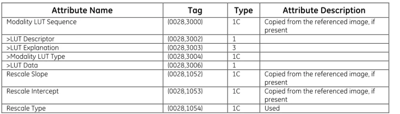
3.3.5.9 MO D A L I T Y LUT MO D U L E
Table 3-16
MODALITY LUT MODULE ATTRIBUTES
Attribute Name Tag Type Attribute Description
Modality LUT Sequence (0028,3000) 1C Copied from the referenced image, if present
>LUT Descriptor (0028,3002) 1 >LUT Explanation (0028,3003) 3 >Modality LUT Type (0028,3004) 1C >LUT Data (0028,3006) 1
Rescale Slope (0028,1052) 1C Copied from the referenced image, if present
Rescale Intercept (0028,1053) 1C Copied from the referenced image, if present
3.3.5.10 SO F T C O P Y VOI LUT MO D U L E
Table 3-17
SOFTCOPY VOI LUT MODULE ATTRIBUTES
Attribute Name Tag Type Use
Softcopy VOI LUT Sequence (0028,3110) 1
>Referenced Image Sequence (0008,1140) 1C Used >>Referenced SOP Class UID (0008,1150) 1C
>>Referenced SOP Instance UID (0008,1155) 1C
>>Referenced Frame Number (0008,1160) 1C Used if referencing a frame in multi-frame image
>VOI LUT Sequence (0028,3010) 1C Used if applied to the referenced image >>LUT Descriptor (0028,3002) 1
>>LUT Explanation (0028,3003) 3 >>LUT Data (0028,3006) 1
>Window Center (0028,1050) 1C A single Value is provided >Window Width (0028,1051) 1C A single Value is provided >Window Center & Width Explanation (0028,1055) 3 Not Used
>VOI LUT Function (0028,1056) 3 Not Used
3.3.5.11 SO F T C O P Y PR E S E N T A T I O N LUT MO D U L E
Table 3-18
SOFTCOPY PRESENTATION LUT MODULE ATTRIBUTES
Attribute Name Tag Type Use
Presentation LUT Sequence (2050,0010) 1C Not Used >LUT Descriptor (0028,3002) 1
>LUT Explanation (0028,3003) 3 >LUT Data (0028,3006) 1
Presentation LUT Shape (2050,0020) 1C Enumerated Values used: IDENTITY
INVERSE
3.3.5.12 SOP CO M M O N MO D U L E
Table 3-19
SOP COMMON MODULE ATTRIBUTES
Attribute Name Tag Type Attribute Description
SOP Class UID (0008,0016) 1
SOP Instance UID (0008,0018) 1 Generated using the internal computer clock
Specific Character Set (0008,0005) 1C Set according to the system
configuration. Defined terms shown in Table 2.7-1
Instance Creation Date (0008,0012) 3 Used Instance Creation Time (0008,0013) 3 Used Instance Creator UID (0008,0014) 3 Not Used
3.4
P
RIVATED
ATAA
TTRIBUTESThe Product supports the Standard and Private Attributes defined in the following sections in Standard Extended GSPS SOP Instances as Type 3 data elements.
3.4.1
Private Group GEIIS_IW
Private Group GEIIS_IW is modeled as part of the Presentation State Information Entity.
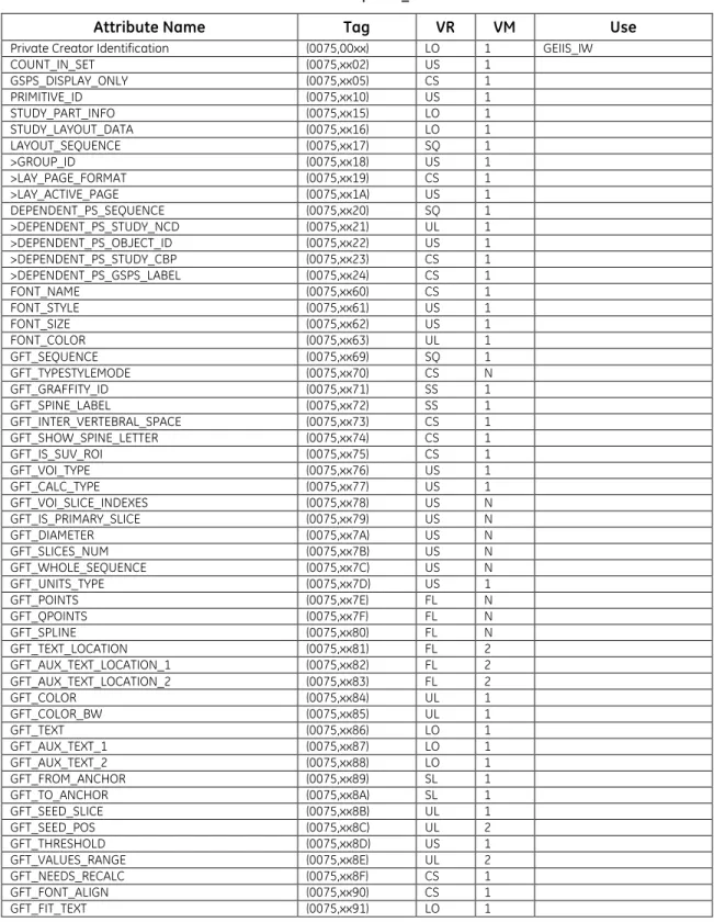
Table 3-20 Private Group GEIIS_IW
Attribute Name Tag VR VM Use
Private Creator Identification (0075,00xx) LO 1 GEIIS_IW COUNT_IN_SET (0075,xx02) US 1 GSPS_DISPLAY_ONLY (0075,xx05) CS 1 PRIMITIVE_ID (0075,xx10) US 1 STUDY_PART_INFO (0075,xx15) LO 1 STUDY_LAYOUT_DATA (0075,xx16) LO 1 LAYOUT_SEQUENCE (0075,xx17) SQ 1 >GROUP_ID (0075,xx18) US 1 >LAY_PAGE_FORMAT (0075,xx19) CS 1 >LAY_ACTIVE_PAGE (0075,xx1A) US 1 DEPENDENT_PS_SEQUENCE (0075,xx20) SQ 1 >DEPENDENT_PS_STUDY_NCD (0075,xx21) UL 1 >DEPENDENT_PS_OBJECT_ID (0075,xx22) US 1 >DEPENDENT_PS_STUDY_CBP (0075,xx23) CS 1 >DEPENDENT_PS_GSPS_LABEL (0075,xx24) CS 1 FONT_NAME (0075,xx60) CS 1 FONT_STYLE (0075,xx61) US 1 FONT_SIZE (0075,xx62) US 1 FONT_COLOR (0075,xx63) UL 1 GFT_SEQUENCE (0075,xx69) SQ 1 GFT_TYPESTYLEMODE (0075,xx70) CS N GFT_GRAFFITY_ID (0075,xx71) SS 1 GFT_SPINE_LABEL (0075,xx72) SS 1 GFT_INTER_VERTEBRAL_SPACE (0075,xx73) CS 1 GFT_SHOW_SPINE_LETTER (0075,xx74) CS 1 GFT_IS_SUV_ROI (0075,xx75) CS 1 GFT_VOI_TYPE (0075,xx76) US 1 GFT_CALC_TYPE (0075,xx77) US 1 GFT_VOI_SLICE_INDEXES (0075,xx78) US N GFT_IS_PRIMARY_SLICE (0075,xx79) US N GFT_DIAMETER (0075,xx7A) US N GFT_SLICES_NUM (0075,xx7B) US N GFT_WHOLE_SEQUENCE (0075,xx7C) US N GFT_UNITS_TYPE (0075,xx7D) US 1 GFT_POINTS (0075,xx7E) FL N GFT_QPOINTS (0075,xx7F) FL N GFT_SPLINE (0075,xx80) FL N GFT_TEXT_LOCATION (0075,xx81) FL 2 GFT_AUX_TEXT_LOCATION_1 (0075,xx82) FL 2 GFT_AUX_TEXT_LOCATION_2 (0075,xx83) FL 2 GFT_COLOR (0075,xx84) UL 1 GFT_COLOR_BW (0075,xx85) UL 1 GFT_TEXT (0075,xx86) LO 1 GFT_AUX_TEXT_1 (0075,xx87) LO 1 GFT_AUX_TEXT_2 (0075,xx88) LO 1 GFT_FROM_ANCHOR (0075,xx89) SL 1 GFT_TO_ANCHOR (0075,xx8A) SL 1 GFT_SEED_SLICE (0075,xx8B) UL 1 GFT_SEED_POS (0075,xx8C) UL 2 GFT_THRESHOLD (0075,xx8D) US 1 GFT_VALUES_RANGE (0075,xx8E) UL 2 GFT_NEEDS_RECALC (0075,xx8F) CS 1 GFT_FONT_ALIGN (0075,xx90) CS 1 GFT_FIT_TEXT (0075,xx91) LO 1
Attribute Name Tag VR VM Use COPY_INDEX (0075,xx92) US 1 GFT_GSPS_RECALC (0075,xx93) CS 1 PS_OVERLAY_STATE (0075,xx1B) CS 1 GFT_OID_SEQID (0075,xxC0) UI 1 GFT_OID_IMAGEID (0075,xxC1) UI 1 GFT_OID_COPY_INDEX (0075,xxC2) SS 1
3.4.2
Private Group GEIIS_RA1000
Private Group GEIIS_RA1000 is modeled as part of the Presentation State Information Entity.
Table 3-21 Private Group GEIIS_RA1000
Attribute Name Tag VR VM Use
Private Creator Identification (0071,00xx) LO 1 GEIIS_RA1000 Private GSPS Type (0071,xx10) CS 1 2 possible values:
DISPLAYLIST and NONDISPLAYLIST Private Font Name (0071,xx20) ST 1 Font used for Text
Annotation
Private Font Style (0071,xx21) US 1 Style code of the font used for Text Annotation Private Font Size (0071,xx22) US 1 Point Size of the font used
for Text Annotation Annotation State View (0071,xx23) US 1 Index for an annotation that
corresponds to the order it should appear in the statistics view display of the workstation
4.
KEY OBJECT SELECTION
IOD
IMPLEMENTATION
4.1
I
NTRODUCTIONThis section specifies the use of the DICOM Key Object Selection Document IOD to represent results produced by the Universal Viewer implementation. Corresponding attributes are conveyed using the module construct.
Universal Viewer can create Key Object Selection instances explicitly or they may be created automatically when a user selects to export the internal set of key images (print pages). The images that are referenced by the KOS object are selected by placing them into the placeholders of the Print Page template. In addition, a set of GSPS objects are created to reflect the presentation state of each of the images.
Note: The print page template information as well as annotations placed on the page and not on a
particular image are not recorded in the KOS object.
The Key Object Selection Document is rendered in the form of Universal Viewer Print Page Key Image Set, where images are displayed in the placeholders of the default Print Page Template.
Universal Viewer supports rendering of instances of the Storage SOP Classes as defined in Table 2-1 referenced in Key Object Selection Document provided the referenced instances are locally stored. If the referenced instances are not locally stored, the application will display an error message in the corresponding placeholder.
4.2
M
APPING OFDICOM
E
NTITIESUniversal Viewer maps DICOM Information Entities to local information entities in the product’s database and user interface.
Table 4-1
Mapping of Dicom Entities to Local Entities
DICOM IE Local Entity
Patient Patient
Study Study
Series Series
Presentation State Presentation State
4.3
IOD
M
ODULET
ABLEThe Key Object Selection Definition comprises the modules of the following table, plus Standard Extended and Private attributes. Standard Extended and Private attributes are described in Section 5.4.
Table 4-2 GSPS IOD MODULES
Entity Name Module Name Usage Reference
Patient Patient Clinical Trial Subject Used Not Used 3.3.1.1 Study General Study Patient Study Used Not Used 3.3.2.1
Clinical Trial Study Not Used
Series Key Object Document Series Clinical Trial Series Used Not Used 4.4.1.1 Equipment General Equipment Used 3.3.4.1
Entity Name Module Name Usage Reference Document
Key Object Document Used 4.4.2.1 SR Document Content Used 4.4.2.2 SOP Common Used 3.3.5.12
4.4
I
NFORMATIONM
ODULED
EFINITIONSPlease refer to DICOM Part 3 (Information Object Definitions) for a description of each of the entities, modules, and attributes contained within the Key Object Selection Document Information Object. The following modules are included to convey Enumerated Values, Defined Terms, and Optional Attributes supported. Type 1 & Type 2 Attributes are also included for completeness and to define what values they may take and where these values are obtained from when generating the instance. It should be noted that they are the same ones as defined in the DICOM Standard Part 3 (Information Object Definitions). Also note that Attributes not present in tables are not supported.
4.4.1
Series Entity Modules
4.4.1.1 KE Y OB J E C T DO C U M E N T SE R I E S MO D U L E
Table 4-3
KEY OBJECT DOCUMENT SERIES MODULEATTRIBUTES
Attribute Name Tag Type Use
Modality (0008,0060) 1 Value = KO Series Instance UID (0020,000E) 1
Series Number (0020,0011) 1
Series Date (0008,0021) 3 Used Series Time (0008,0031) 3 Used Series Description (0008,103E) 3 Used
Referenced Performed Procedure Step Sequence (0008,1111) 2 Not Used– Set as empty
4.4.2
Document Entity Modules
4.4.2.1 KE Y OB J E C T DO C U M E N T MO D U L ETable 4-4
KEY OBJECT DOCUMENT MODULE ATTRIBUTES
Attribute Name Tag Type Use
Instance Number (0020,0013) 1 Content Date (0008,0023) 1 Content Time (0008,0033) 1 Referenced Request Sequence (0040,A370) 1C >Study Instance UID (0020,000D) 1 >Referenced Study Sequence (0008,1110) 2 >>Include ‘SOP Instance Reference Macro’
>Accession Number (0008,0050) 2 >Placer Order Number/Imaging Service Request (0040,2016) 2 >Filler Order Number/Imaging Service Request (0040,2017) 2 >Requested Procedure ID (0040,1001) 2 >Requested Procedure Description (0032,1060) 2 >Requested Procedure Code Sequence (0032,1064) 2 >>Include ‘Code Sequence Macro’
Current Requested Procedure Evidence Sequence (0040,A375) 1 >Include ‘Hierarchical SOP Instance Reference
Attribute Name Tag Type Use Identical Documents Sequence (0040,A525) 1C Not used
>Include ‘Hierarchical SOP Instance Reference Macro’
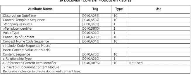
4.4.2.2 SR DO C U M E N T CO N T E N T MO D U L E
Table 4-5
SR DOCUMENT CONTENT MODULE ATTRIBUTES
Attribute Name Tag Type Use
Observation DateTime (0040,A032) 1C Content Template Sequence (0040,A504) 1C >Mapping Resource (0008,0105) 1 >Template Identifier (0040,DB00) 1 Value Type (0040,A040) 1 Continuity of Content (0040,A050) 1C Concept Name Code Sequence (0040,A043) 1C >Include ‘Code Sequence Macro’
Insert Concept Value attribute(s)
Content Sequence (0040,A730) 1C > Relationship Type (0040,A010) 1
> Referenced Content Item Identifier (0040,DB73) 1C Not used > Insert SR Document Content Module
Recursive inclusion to create document content tree.
See section 4.4.2.2.1 for the list of supported templates 4.4.2.2.1 SR DO C U M E N T CO N T E N T DE S C R I P T I O N S
4.4.2.2.1.1 CO N T E N T TE M P L A T E
The product supports the following root Templates for SR SOP Instances created, processed, or displayed by the product.
Table 4-6 SR Root Templates
SOP Class Template ID Template Name Use
Key Object Selection
Document 2010 Key Object Selection Create/Display
4.4.2.2.1.2 ST A N D A R D TE M P L A T E S
Universal Viewer supports the following standard templates for KOS SOP Instances created by this product.
4.4.2.2.1.3 TE M P L A T E ID 2010 KE Y OB J E C T SE L E C T I O N
TABLE 4-7
TID 2010 – KEY OBJECT SELECTION TEMPLATE
NL Rel with Parent VT Concept Name VM Type Req Usage
1 CONTAINER CID(7010) Key Object Selection Document
NL Rel with Parent VT Concept Name VM Type Req Usage
2 > HAS CONCEPT MOD CODE (113011, DCM, "Document Title
Modifier") 1-n U Used
3 > HAS CONCEPT MOD CODE (113011, DCM, "Document Title
Modifier") 1 UC
Used
When Concept Name is (113001, DCM, "Rejected for Quality Reasons") or (113010, DCM," Quality Issue") 4 > HAS CONCEPT MOD CODE (113011, DCM, "Document Title
Modifier") 1 MC
Used
When Concept Name is (113013, DCM, "Best In Set")
5 > HAS CONCEPT MOD INCLUDE TID(1204) Language of Content Item and
Descendants 1 U Used 6 > HAS OBS CONTEXT INCLUDE TID(1002) Observer Context 1-n U
Used
Only one instance is supported 7 > CONTAINS TEXT (113012, DCM, ”Key Object Description”) 1 U Used 8 > CONTAINS IMAGE Purpose of Reference shall not be present 1-n MC Used 9 > CONTAINS WAVEFORM Purpose of Reference shall not be present 1-n MC Not Supported 10 > CONTAINS COMPOSITE Purpose of Reference shall not be present 1-n MC Not Supported
TABLE 4-8
TID 1204 – LANGUAGE OF CONTENT ITEM AND DESCENDANTS
NL Rel with Parent VT Concept Name VM Type Req Usage
1 HAS CONCEPT MOD CODE (121049,DCM,”Language of Content Item and
Descendants”) 1 M Used 2 > HAS CONCEPT MOD CODE (121046,DCM,”Country of Language”) 1 U Not Used
TABLE 4-9
TID 1002 – OBSERVER CONTEXT
NL Rel with Parent VT Concept Name VM Type Req Usage
1 HAS OBS CONTEXT CODE (121005,DCM, “Observer Type”) 1 MC
Used Observer Type is always (121006,DCM, “Person”) 2 HAS OBS CONTEXT INCLUDE TID (1003) Person observer identifying attributes 1 MC Used 3 HAS OBS CONTEXT INCLUDE TID (1004) Device observer
identifying attributes 1 MC Not Supported TABLE 4-10
TID 1003 – PERSON OBSERVER IDENTIFYING ATTRIBUTES
NL Rel with Parent VT Concept Name VM Type Req Usage 1 PNAME (121008,DCM, “Person
Observer Name”) 1 M Used 2 TEXT (121009,DCM, “Person
Observer’s Organization Name”)
1 U Not Used 3 CODE (121010,DCM, “Person
Observer’s Role in the Organization”)
1 U Not Used 4 CODE (121011,DCM, “Person
Observer’s Role in this Procedure”)
1 U Not Used
4.5
PRIVATE
DATA
ATTRIBUTES
The Product supports the Standard and Private Attributes defined in the following sections in Standard Extended KOS SOP Instances as Type 3 data elements.
4.5.1
Private Group GEIIS_IW
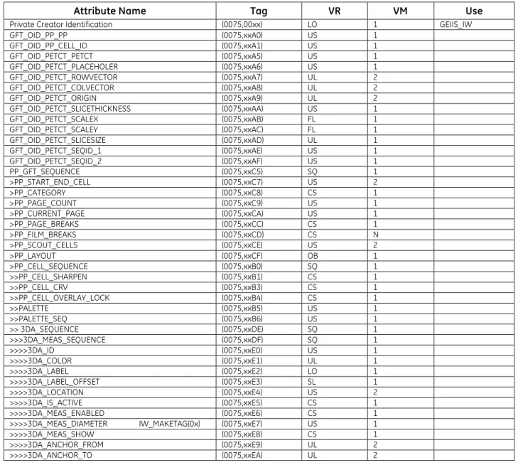
Table 4-11 Private Group GEIIS_IW
Attribute Name Tag VR VM Use
Private Creator Identification (0075,00xx) LO 1 GEIIS_IW
GFT_OID_PP_PP (0075,xxA0) US 1 GFT_OID_PP_CELL_ID (0075,xxA1) US 1 GFT_OID_PETCT_PETCT (0075,xxA5) US 1 GFT_OID_PETCT_PLACEHOLER (0075,xxA6) US 1 GFT_OID_PETCT_ROWVECTOR (0075,xxA7) UL 2 GFT_OID_PETCT_COLVECTOR (0075,xxA8) UL 2 GFT_OID_PETCT_ORIGIN (0075,xxA9) UL 2 GFT_OID_PETCT_SLICETHICKNESS (0075,xxAA) US 1 GFT_OID_PETCT_SCALEX (0075,xxAB) FL 1 GFT_OID_PETCT_SCALEY (0075,xxAC) FL 1 GFT_OID_PETCT_SLICESIZE (0075,xxAD) UL 1 GFT_OID_PETCT_SEQID_1 (0075,xxAE) US 1 GFT_OID_PETCT_SEQID_2 (0075,xxAF) US 1 PP_GFT_SEQUENCE (0075,xxC5) SQ 1 >PP_START_END_CELL (0075,xxC7) US 2 >PP_CATEGORY (0075,xxC8) CS 1 >PP_PAGE_COUNT (0075,xxC9) US 1 >PP_CURRENT_PAGE (0075,xxCA) US 1 >PP_PAGE_BREAKS (0075,xxCC) CS 1 >PP_FILM_BREAKS (0075,xxCD) CS N >PP_SCOUT_CELLS (0075,xxCE) US 2 >PP_LAYOUT (0075,xxCF) OB 1 >PP_CELL_SEQUENCE (0075,xxB0) SQ 1 >>PP_CELL_SHARPEN (0075,xxB1) CS 1 >>PP_CELL_CRV (0075,xxB3) CS 1 >>PP_CELL_OVERLAY_LOCK (0075,xxB4) CS 1 >>PALETTE (0075,xxB5) US 1 >>PALETTE_SEQ (0075,xxB6) US 1 >> 3DA_SEQUENCE (0075,xxDE) SQ 1 >>>3DA_MEAS_SEQUENCE (0075,xxDF) SQ 1 >>>>3DA_ID (0075,xxE0) US 1 >>>>3DA_COLOR (0075,xxE1) UL 1 >>>>3DA_LABEL (0075,xxE2) LO 1 >>>>3DA_LABEL_OFFSET (0075,xxE3) SL 1 >>>>3DA_LOCATION (0075,xxE4) US 2 >>>>3DA_IS_ACTIVE (0075,xxE5) CS 1 >>>>3DA_MEAS_ENABLED (0075,xxE6) CS 1 >>>>3DA_MEAS_DIAMETER IW_MAKETAG(0x) (0075,xxE7) US 1 >>>>3DA_MEAS_SHOW (0075,xxE8) CS 1 >>>>3DA_ANCHOR_FROM (0075,xxE9) UL 2 >>>>3DA_ANCHOR_TO (0075,xxEA) UL 2