Department of
Defence
Defence Support and Reform Group
Spatial Data Management Plan
DRMS Document Id:
R1830735Version:
4.6.0
Status:
Draft
Dated:
01 March 2015
EXECUTIVE SUMMARY
The Defence Support and Reform Group (DSRG) Spatial Data Management Plan (SDMP) has been developed to provide standards and specifications for spatial data management. The standards and specifications within the SDMP will improve data consistency and availability of information, and facilitate spatial information dissemination and sharing within DSRG. With its use, DSRG will achieve a standardised approach to spatial data management that will realise many benefits to both the organisation and its staff including:
Consistent and more reliable data that will lead to more informed decision making; Closer integration with other DSRG information systems and Defence spatial data users Portability of staff skills; and
Greater interoperability with organisations outside of Defence.
The SDMP shall be used by spatial data users both within Defence and Defence Contractors, and data managers within DSRG. It is the responsibility of data users to implement the SDMP Specifications and produce data in accordance with the specifications. Data Users shall implement all requirements defined in Section 2, and the specific data requirements in Sections 3 onwards as determined by the type of data to be created or updated.
The SDMP is made up of three main Sections:
Section 1 provides an introduction to the SDMP, the scope of implementation and other background information to the document.
Section 2 contains the General Data Specification that describes data formats, file naming conventions, metadata requirements, the approved datum and coordinate systems, measurement units, accuracy and other DSRG data standards.
Sections 3 onwards contain a set of specific data type specifications that shall be implemented by all spatial data users. The data specifications cover the key DSRG data types, the Master Site Plan and the Spaces (Floor) Plans, in addition to specifications for engineering detail survey, aerial photography, master planning, environmental data and other data types.
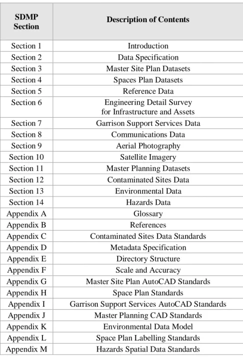
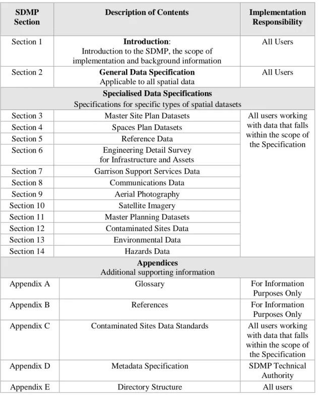
Appendices support the SDMP, providing detail of the DSRG Spatial Data Management Specification, the full Metadata Specification and additional appendices to support the core data specification and data type specifications. Table E-1 summarises the information held within each Section and Appendix.
Table E-1 SDMP Sections and Appendices
SDMP
Section Description of Contents
Section 1 Introduction
Section 2 Data Specification
Section 3 Master Site Plan Datasets
Section 4 Spaces Plan Datasets
Section 5 Reference Data
Section 6 Engineering Detail Survey
for Infrastructure and Assets
Section 7 Garrison Support Services Data
Section 8 Communications Data
Section 9 Aerial Photography
Section 10 Satellite Imagery
Section 11 Master Planning Datasets
Section 12 Contaminated Sites Data
Section 13 Environmental Data
Section 14 Hazards Data
Appendix A Glossary
Appendix B References
Appendix C Contaminated Sites Data Standards
Appendix D Metadata Specification
Appendix E Directory Structure
Appendix F Scale and Accuracy
Appendix G Master Site Plan AutoCAD Standards
Appendix H Space Plan Standards
Appendix I Garrison Support Services AutoCAD Standards
Appendix J Master Planning CAD Standards
Appendix K Environmental Data Model
Appendix L Space Plan Labelling Standards
Appendix M Hazards Spatial Data Standards
A set of template datasets are provided as part of the SDMP to assist in the implementation of the SDMP specification. The templates are available on the Defence Estate Quality Management System and include example data that has been collected in accordance with the SDMP specifications.
TABLE OF CONTENTS Executive Summary ii Table of Contents iv Version History x 1 Introduction 1 1.1 Purpose of SDMP ... 1
1.2 Spatial Data Definitions ... 1
1.3 Intended Audience ... 3
1.4 Structure of SDMP ... 3
1.5 Application of the SDMP ... 5
1.6 SDMP Point of Contact ... 7
1.7 Linkages with NSIMS ... 7
1.8 DSRG Spatial Data Policy ... 8
1.9 Future Changes to Spatial Data Management... 9
2 General Data Specification 12 2.1 Introduction ... 12 2.2 Data Format ... 12 2.3 File Names ... 15 2.4 Directory Structures ... 15 2.5 Metadata ... 15 2.6 Datums ... 16 2.7 Coordinate Systems ... 17 2.8 Units of Measurement ... 18 2.9 Spatial Accuracy ... 18 2.10 Spatial Scale ... 18 2.11 Data Capture ... 19 2.12 Data Viewing ... 19
2.13 Spatial Integrity of Features - Topology ... 19
2.14 Spatial Integrity of Features – Topology in a CAD Environment ... 21
2.15 Data Attributes ... 23
2.16 Imagery Management – Image Tiling ... 23
2.17 Hardcopy Archival ... 25
2.18 Vectorisation of Information ... 25
Specialised Data Specifications 28 3 Master Site Plan Datasets 29 3.1 Scope of Specification ... 29
3.2 Deliverables ... 30
3.3 Deliverable Templates ... 30
3.4 Data Deliverable Specification ... 30
3.5 Specific Data Requirements ... 31
3.6 Topology Specifications – For Information Only ... 31
3.7 Topology Guidelines ... 32 4 Spaces Plans 34 4.1 Scope of Specification ... 34 4.2 Deliverables ... 35 4.3 Deliverable Templates ... 35 4.4 Required Inputs ... 36
4.5 Data Deliverable Specification ... 36
4.6 Specific Data Requirements ... 37
5 Reference Data 47 5.1 Scope of Specification ... 47
5.2 Deliverables ... 47
5.3 Deliverable Specification – General Reference Documentation ... 47
6 Engineering Detail Survey for Infrastructure and Assets 51
6.1 Scope of Specification ... 51
6.2 Deliverables ... 51
6.3 Data Inputs ... 52
6.4 Deliverable Specification ... 52
6.5 Specific Data Requirements ... 52
7 Garrison Support Services Data 56 7.1 Scope of Specification ... 56
7.2 Status of Specification ... 56
7.3 Deliverables ... 57
7.4 Deliverable Templates ... 58
7.5 Specific Data Requirements ... 58
8 Communications Data 61 8.1 Scope of Specification ... 61
8.2 Deliverables ... 61
8.3 Deliverable Templates ... 61
8.4 Required Inputs ... 62
8.5 Specific Data Requirements ... 62
8.6 Field Capture... 62 8.7 Data Capture ... 62 9 Aerial Photography 69 9.1 Scope of Specification ... 69 9.2 Deliverables ... 69 9.3 Acquisition Requirements ... 69 9.4 Orthophoto Specifications ... 72 9.5 Orthophoto Deliverables ... 73 9.6 Deliverable Specification ... 74
9.7 Quality Assurance Documentation ... 75
9.8 Specific Metadata Requirements ... 76
10 Satellite Imagery 78 10.1 Scope of Specification ... 78
10.2 Background Information ... 78
10.3 Deliverables ... 80
10.4 Deliverable Specification ... 80
10.5 Specific Data Requirements ... 81
11 Master Planning Datasets 84 11.1 Scope of Specification ... 84
11.2 Deliverables ... 86
11.3 Deliverable Templates ... 86
11.4 Deliverable Specification ... 86
12 Contaminated Sites Data 88 12.1 Scope of Specification ... 88
12.2 Deliverables ... 89
12.3 Data Deliverable – Templates ... 89
12.4 Required Inputs ... 89
12.5 Data Deliverable Specification ... 89
13 Environmental Data 92 13.1 Scope of Specification ... 92
13.2 Background Information ... 92
13.3 Data Deliverables ... 93
13.4 Data Deliverable – Templates ... 93
13.5 Data Deliverable Specification ... 93
13.6 Specific Data Requirements ... 93
14.1 Scope of Specification ... 95
14.2 Schedule 11 Hazardous Chemicals Data and Maps (HAZCHEM) ... 95
14.3 Hazardous Areas Data ... 103
14.4 Unexploded Ordnance (UXO) Data ... 105
Tables
Table 1-1 SDMP User Groups ...3Table 1-2 SDMP Sections and Appendices ...4
Table 1-3 Spatial Data Technical Authority ...7
Table 1-4 Principles of the DSRG Spatial Data Policy ...8
Table 2-1 List of Specialised Data Specifications ... 12
Table 2-2 DSRG Spatial Data Formats ... 13
Table 2-3 Recommended Tile Sizes ... 23
Table 3-1 Scope of Master Site Plan Data ... 29
Table 4-1 DEMS Structure Level Codes ... 38
Table 4-2 Office Space Area Calculations ... 41
Table 4-3 Spaces Plan Title Block ... 42
Table 4-4 Spaces Plan - Optional Attributes... 43
Table 4-5 Spaces Plan - Defence Attributes ... 44
Table 4-6 Spaces Floor Plan XData for Window Attributes ... 45
Table 4-7 Spaces Floor Plan XData for Wall Attributes ... 45
Table 5-1 Design and As-Constructed Title Block Requirements ... 49
Table 5-2 Design and As-Constructed Title Block Optional Information ... 49
Table 6-1 Scope of Data Collected using Engineering Detail Survey ... 51
Table 7-1 Garrison Support Service Activities ... 56
Table 7-2 Garrison Support Grounds Maintenance Grass Cuts ... 58
Table 8-1 Communication Pit Data ... 63
Table 8-2 Communications Conduit Data ... 65
Table 8-3 Communication Cable Data ... 66
Table 8-4 Communications Conduit Cable Link Data ... 67
Table 9-1 Orthophoto Options for Resolution and Accuracy ... 74
Table 9-2 Orthophoto Technical Specifications ... 74
Table 9-3 Orthophoto Quality Assurance Plan ... 75
Table 9-4 Aerial Photography Specific Metadata Requirements ... 76
Table 10-1 Satellite Imagery Specific Metadata Requirements ... 80
Table 14-1: Schedule 11 Hazardous Chemicals Workplace Site Map Presentation Guidelines ... 98
Figures
Figure 1-1 Master Site Plan Dataset - example data ...2
Figure 1-2 Spaces Plan Dataset - example data ...2
Figure 1-3 Specification Process Flow Diagram ...6
Figure 2-1 Examples of Correct Topological Representation ... 20
Figure 2-2 Examples of Correct Topological Representation ... 21
Figure 2-3 Incorrect Topology - Unconnected line and point features ... 22
Figure 2-4 Correct Topology - Connected line and point features ... 22
Figure 3-1 Master Site Plan Dataset - example data ... 29
Figure 4-1 Spaces Plan Dataset - example data ... 34
Figure 8-1 Communication Pit Labels... 63
Figure 8-2 Communication Conduit Labels ... 64
Figure 8-3 Communication Cable Labels ... 66
Figure 14-1: Example Workplace Site Map ... 97
Appendices
Appendix A Glossary A-1
Appendix B References B-1
Appendix C Contaminated Sites Data Standards C-1
Appendix D Metadata Specification D-1
Appendix E Directory Structure E-1
Appendix F Scale and Accuracy F-1
Appendix G Master Site Plan AutoCAD Standards G-1
Appendix H Space Plan Data Standards H-1
Appendix I Garrison Support Services AutoCAD Standards I-1
Appendix J Master Planning CAD Standards J-1
Appendix K Environmental Data Model K-1
Appendix L Space Plan Labelling Standards L-1
VERSION HISTORY Version
Number Date Amendment Comment Released By
1.0 Feb 06 Draft John Ramsay
DIIE
3.0 31 Oct 06 Published
Baseline version for release
Includes name change from CSIG to DSG
John Ramsay DIIE
3.1 8 May 07 Draft
Updated SDMP Section 5 Spatial Metadata Specifications v4.4 of 8 May 07. Updated Section 1 Guiding
Principles to numbered paragraphs and added a Table of Contents for the each SDMP section.
The Section 1 version number acts as the overall version number for the entire SDMP. If any section is updated, Section 1 should also be updated.
John Ramsay DIIE
3.2 29 Feb 08 Published
Updated SDMP Section 5 Spatial Metadata Specs v4.5, Section 6 Baseline Spatial Data Specifications v3.1 and Section 7 Spatial Data Specifications v3.1.
Berceuse Bindle DIIE
4.5.1 7 Aug 08 Published Berceuse
Bindle DIIE
4.5.2 21 Dec 11 Draft
Includes name change from DSG to DS. General restructure and revision of SDMP to improve currency, ease-of-use and reduce ambiguity.
Berceuse Bindle DSIM
4.6.0 01 Mar 15 Draft
Update of Section 12 and Appendix C. Addition of section 14 and appendix M for inclusion of Hazards Data
S
ec
ti
o
n
1
I
n
tr
o
d
u
ct
io
n
1 INTRODUCTION 1.1 Purpose of SDMP1.1.1 The Defence Support and Reform Group (DSRG) Spatial Data Management Plan (SDMP) has been developed to provide standards and specifications for spatial data management and has been developed with reference to spatial standards both within Defence and the spatial industry.
1.1.2 The standards and specifications within the SDMP will improve data consistency and availability of information, and facilitate spatial information dissemination and sharing within DSRG. With its use, DSRG will achieve a standardised approach to spatial data management that will realise many benefits to both the organisation and its staff including:
Consistent and more reliable data that will lead to more informed decision making;
Closer integration with other DSRG information systems and Defence spatial data users;
Portability of staff skills; and
Greater interoperability with organisations outside of Defence.
1.1.3 The SDMP has been developed as an initiative of the Directorate of Strategic Information Management (at that time known as the Infrastructure Information Environment - IIE) and forms a component of the Strategic Information Management Directorate (SIM) architecture. The SDMP provides the Data Specification for all data stored and managed within the DSRG National Spatial Information Management System (NSIMS). All spatial data shall meet the SDMP Specification to allow data to be accessed within NSIMS and DSRG Enterprise Level Spatial Systems.
1.2 Spatial Data Definitions
1.2.1 Spatial data is information that defines the geographic location and spatial dimension of natural or constructed features on Earth. Spatial data stores geographic locations as a series of points, lines, and polygons using coordinate systems and topology to record and inform the location of information. Spatial data can be mapped using Computer Aided Design (CAD) or Geographic Information Systems (GIS) software. Defence Support (DSRG) conducts business with the assistance of spatial data in many forms and for many different purposes.
1.2.2 DSRG relies on two Key or Foundation Spatial Datasets upon which other spatial data is developed and referenced. These Key Spatial Datasets types are -
Master Site Plan Dataset Spaces Plan Dataset
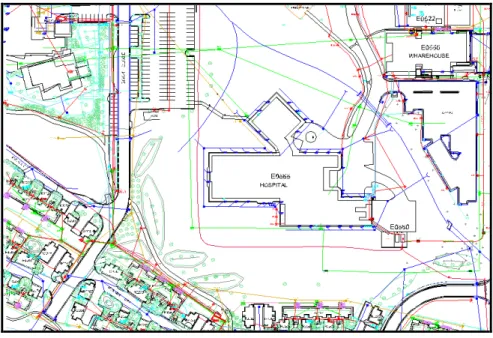
1.2.3 A Master Site Plan Dataset exists for all key Defence Properties and contains the locations of natural and man-made features such as buildings, road, runways, and services. This dataset is used to plan and design new infrastructure on properties,
S
ec
ti
o
n
1
I
n
tr
o
d
u
ct
io
n
and is used as a basis for the capture of garrison support services data. A sample of data from a Master Site Plan Dataset is shown in Figure 1-1.
Figure 1-1 Master Site Plan Dataset - example data
A Spaces Plan Dataset or Floor Plan is created for all key Defence Buildings and is distinct from an architectural floor plan in that it only shows the size, shape layout and identification number of spaces and rooms within Defence Buildings, door openings, staircases and fittings. The data captured is used to assist in building management through the allotment of rooms, cleaning services, management of information technology assets and changes to buildings. A sample of data from a Spaces Plan Dataset is shown in Figure 1-2.
S
ec
ti
o
n
1
I
n
tr
o
d
u
ct
io
n
1.2.4 Other common spatial data used by DSRG includes: Aerial photography and satellite imagery;
Reference documentation including design and as-constructed plans of DSRG structures, assets and infrastructure, and associated reports; and
Environmental data and information overlays including environmental monitoring, heritage, contaminated sites data, weed and fire mapping.
1.3 Intended Audience
1.3.1 The SDMP is intended for use by those creating, using and managing spatial data within, and on behalf of, the Defence Support and Reform Group (DSRG).
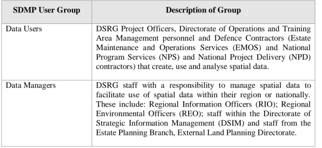
1.3.2 There are two key SDMP User Groups that are referred to within the SDMP, these are listed in Table 1-1.
Table 1-1 SDMP User Groups
SDMP User Group Description of Group
Data Users DSRG Project Officers, Directorate of Operations and Training
Area Management personnel and Defence Contractors (Estate Maintenance and Operations Services (EMOS) and National Program Services (NPS) and National Project Delivery (NPD) contractors) that create, use and analyse spatial data.
Data Managers DSRG staff with a responsibility to manage spatial data to
facilitate use of spatial data within their region or nationally. These include: Regional Information Officers (RIO); Regional Environmental Officers (REO); staff within the Directorate of Strategic Information Management (DSIM) and staff from the Estate Planning Branch, External Land Planning Directorate.
1.4 Structure of SDMP
1.4.1 The SDMP contains two types of Standards: The General Data Specification (Section 2).
Specialised Data Specifications (Section 3 onwards).
The General Data Specification (Section 2) contains the Data Specification that applies to all spatial data. The General Specification prescribes the data formats, file naming conventions, metadata requirements, the approved datum and
coordinate systems, measurement units, accuracy and other DSRG data standards. Specialised Data Specifications (Sections 3 onwards) contain a set of
S
ec
ti
o
n
1
I
n
tr
o
d
u
ct
io
n
DSRG Key Spatial Datasets are detailed, and specifications for other types of Spatial Data.
Appendices provide additional support to the SDMP. The appendices include the Spatial Data Management Specification, the full Metadata Specification and additional appendices to support the general data specification and specialised data specifications.
Table 1-2 summarises the information held within each Section and Appendix. Table 1-2 SDMP Sections and Appendices
SDMP Section
Description of Contents Implementation Responsibility
Section 1 Introduction:
Introduction to the SDMP, the scope of implementation and background information
All Users
Section 2 General Data Specification
Applicable to all spatial data
All Users Specialised Data Specifications
Specifications for specific types of spatial datasets
Section 3 Master Site Plan Datasets All users working
with data that falls within the scope of the Specification
Section 4 Spaces Plan Datasets
Section 5 Reference Data
Section 6 Engineering Detail Survey
for Infrastructure and Assets
Section 7 Garrison Support Services Data
Section 8 Communications Data
Section 9 Aerial Photography
Section 10 Satellite Imagery
Section 11 Master Planning Datasets
Section 12 Contaminated Sites Data
Section 13 Environmental Data
Section 14 Hazards Data
Appendices
Additional supporting information
Appendix A Glossary For Information
Purposes Only
Appendix B References For Information
Purposes Only
Appendix C Contaminated Sites Data Standards All users working
with data that falls within the scope of the Specification
Appendix D Metadata Specification SDMP Technical
Authority
S
ec
ti
o
n
1
I
n
tr
o
d
u
ct
io
n
Appendix F Scale and Accuracy For Information
Purposes Only
Appendix G Master Site Plan AutoCAD Standards All users working
with data that falls within the scope of the Specification
Appendix H Space Plan Standards
Appendix I Garrison Support Services AutoCAD Standards
Appendix J Master Planning CAD Standards
Appendix K Environmental Data Model
Appendix L Space Plan Labelling Standards
Appendix M Hazards Spatial Data Standards
Associated Documents
A set of template datasets are provided as part of the SDMP to assist in the implementation of the SDMP specification. The templates are available on the Defence Estate Quality Management System (DEQMS) site and include example data that has been collected in accordance with the SDMP specifications.
http://www.defence.gov.au/estatemanagement/Default.asp 1.5 Application of the SDMP
1.5.1 The SDMP shall be applied by DSRG technical and business owners, spatial data managers and their representatives. This includes the Estate Planning Branch, External Land Planning Directorate and Defence Support Operations (DSO) services providers, Estate Maintenance and Operations Services (EMOS) and National Program Services (NPS) and National Project Delivery (NPD) contractors. All are responsible for the appropriate application of standards and the implementation of the SDMP requirement accordingly.
1.5.2 The SDMP specification process flow shall be applied as described below in Figure 1-3.
S
ec
ti
o
n
1
I
n
tr
o
d
u
ct
io
n
Garrison Support Services Data Section 7 Communications Data Section 8 Aerial Photography Section 9 Satellite Imagery Section 10 Master Planning Datasets Section 11 Contaminated Sites Data Section 12 Environmental Data Section 13 Hazards Data Section 14
S
ec
ti
o
n
1
I
n
tr
o
d
u
ct
io
n
1.6 SDMP Point of Contact1.6.1 General Note About Data: The DSRG spatial capability is currently going through a process of transition from file-based data formats to specifications for geodatabases. Through this transition the DSRG Spatial Data Technical Authority will act as the point of contact for questions relating to the SDMP, the data specifications within the SDMP and DSRG Spatial Data. Contact details for the DSRG Spatial Data Technical Authority are provided in Table 1-3.
Table 1-3 Spatial Data Technical Authority
DSRG Spatial Data Technical Authority
Position Manager Spatial Systems
Section:
Department of Defence Defence Support
Chief Operating Officer Division
Strategic Planning and Performance Management Branch Directorate of Strategic Information Management Address: F3-GF-063, Fairbairn Park Offices, Fairbairn, ACT
Telephone: +61 2 6128 7788
Facsimile: +61 2 6128 7700
Email: Spatial Information Systems group mailbox [email protected]
1.7 Linkages with NSIMS
1.7.1 The National Spatial Information Management System (NSIMS) is currently the DSRG repository for all DSRG Spatial Information and is supported by the SDMP. NSIMS is located within the Defence Restricted Network (DRN) and is access managed.
1.7.2 NSIMS includes the following components:
A spatial dataset metadata catalogue for searching and locating spatial and aspatial data;
A gazetteer for defining and performing searches on geographic extents of a named feature;
A viewing tool that allows spatial datasets to be displayed; and
A tool to allow datasets to be uploaded to, and downloaded from, the system. 1.7.3 All DSRG spatial data can be stored within NSIMS if the data meets the
S
ec
ti
o
n
1
I
n
tr
o
d
u
ct
io
n
1.8 DSRG Spatial Data Policy
1.8.1 The principles of the DSRG Spatial Data Policy are described in and shall be adhered to by all DSRG spatial data users.
Table 1-4 Principles of the DSRG Spatial Data Policy
Principle Description User Responsibility
Data Standards apply to all DSRG Spatial Data
The Standards and Specifications within the SDMP apply to DSRG Spatial Data. Specific standards apply to specific spatial datasets including the DSRG Key Spatial Datasets and other spatial data.
When considering the relevance and application of the SDMP specification, spatial data providers and managers should consider which section of the SDMP specification shall be applied to spatial datasets.
Information is a Defence Asset
Spatial Information shall be valued and protected as a key Defence asset.
Arrangements shall be in place to protect DSRG’s information assets in the event of its complete or partial loss, or destruction.
Security Management of spatial data shall include arrangements to preserve confidentiality, privacy, security and intellectual property rights which will protect the rights of data owners and
appropriate sectors of the Defence stakeholder community.
The provision of Defence information is permitted on a “Needs to Know” basis. Defence data shall not be
provided to a third-party without direct approval and the implementation of a Data License. Data shall be managed in such a way that security is
maintained at all times.
Adherence to Standards
Data shall be collected, stored and disseminated according to Defence Standards and
specifications.
The SDMP identifies the applicability and scope of minimum spatial data standards and shall be applied for DSRG Spatial Data.
DSRG “Contract Documents” may identify additional specific
requirements that shall be applied. Interoperability Data shall be gathered in a
manner that is independent of specific vendor applications and readily integrated with other systems that adhere to this principle.
To the extent practicable, all spatial data that is provided in reports, and designed and produced for Defence shall have the widest benefit to the broader DSRG business, and to
existing data and information systems. Access Data
from its Point of Truth
Data shall be acquired from a point as close to its (the data’s) source as possible.
All finalised spatial data should be stored within NSIMS to allow DSRG to access a single data source and minimise the requirement to obtain multiple versions of data from external
S
ec
ti
o
n
1
I
n
tr
o
d
u
ct
io
n
Principle Description User Responsibility
Documented Metadata documentation shall be collected and maintained. Proper documentation of spatial data will ensure data is stored and can be retrieved logically and appropriately in support of DSRG operations and decision making.
The DSRG Metadata Entry Tool (MET) shall be used to create and edit metadata to provide documentation of spatial datasets. The MET can be downloaded from:
http://www.defence.gov.au/estatemana gement/Default.asp
Data shall be Shared
Spatial information shall be made accessible and
leveraged across the Defence Restricted Network (DRN) to enable improved decision making and minimise costs to Defence e.g. due to
duplication.
Data shall be openly available to all DRN users through the use of NSIMS to maximise the benefit of the data to the organisation as a whole.
NSIMS shall be used to store and access spatial data to ensure that data is shared between DRN users. Data gathering initiatives shall avoid unnecessary duplication of effort, and the consequent risks of unnecessary expenditure and inconsistent data.
Data shall be Collected with Assured Integrity
Data shall be entered only once into Defence systems. There shall be a single authoritative source for each data element.
NSIMS custodian and user roles shall be used to manage spatial data
integrity within NSIMS.
Authoritative DRN users shall have access to valid, reliable, complete data they can use with confidence to support improved decision making.
NSIMS shall be used to store and access spatial data to ensure that the most current and complete spatial data is available to DRN users.
Errors and Omissions
Errors or omissions found in any dataset shall be rectified prior to final delivery or reported as soon as practical to the DSRG business owner or NSIMS Custodian.
NSIMS validates spatial dataset against SDMP requirements prior to upload in NSIMS.
DRN users should report errors, omissions and improvement actions via the NSIMS issue feedback link. 1.9 Future Changes to Spatial Data Management
1.9.1 The SDMP is currently going through a process of staged revision with the implementation of the National Spatial Information Management System (NSIMS), the Garrison and Estate Management System (GEMS) Data Model and the transition from file-based data formats to specifications for Geodatabases. As part of this revision some of the SDMP data specifications will be revised to meet the requirements of the new systems and data formats. Contact the DSRG Spatial Data
S
ec
ti
o
n
1
I
n
tr
o
d
u
ct
io
n
Technical Authority for further information regarding the revision schedule and implications for data capture projects.
1.9.2 Currently a Geodatabase Model is being designed for the Master Site Plan Dataset. It is anticipated that this will be implemented later in 2014. A Geodatabase Model for other DSRG Data will be implemented over time.
S
ec
ti
o
n
2
G
en
er
al
D
at
a
S
p
ec
if
ic
at
io
n
S
ec
ti
o
n
2
G
en
er
al
D
at
a
S
p
ec
if
ic
at
io
n
2 GENERAL DATA SPECIFICATION
2.1 Introduction
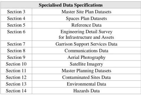
2.1.1 This section defines the General Data Specification and standards for spatial data. Specific or additional requirements are provided within the Specialised Data Specifications in Sections 3 onwards. The Specialised Data Specification for the type of data being created or updated must be read in conjunction with the General Data Specification. See Table 2-1 for a list of the Specialised Data Specifications. Table 2-1 List of Specialised Data Specifications
Specialised Data Specifications
Section 3 Master Site Plan Datasets
Section 4 Spaces Plan Datasets
Section 5 Reference Data
Section 6 Engineering Detail Survey
for Infrastructure and Assets
Section 7 Garrison Support Services Data
Section 8 Communications Data
Section 9 Aerial Photography
Section 10 Satellite Imagery
Section 11 Master Planning Datasets
Section 12 Contaminated Sites Data
Section 13 Environmental Data
Section 14 Hazards Data
2.1.2 The SDMP shall be applied by DSRG technical and business owners, spatial data managers and their representatives. This includes Infrastructure Division (ID) and Defence Support Operations (DSO) services providers, Estate Maintenance and Operations Services (EMOS) and National Program Services (NPS) and National Project Delivery (NPD) contractors. All are responsible for the appropriate application of standards and the implementation of the SDMP requirement accordingly.
2.2 Data Format
S
ec
ti
o
n
2
G
en
er
al
D
at
a
S
p
ec
if
ic
at
io
n
Table 2-2 DSRG Spatial Data Formats
Information Type Preferred Format Extension Comments CAD (Computer
Aided Design) Data
AutoCAD Drawing file* DWG* Shall be compatible with
AutoCAD Release 2007
GIS Data ESRI Shapefile SHP, SHX
and DBF
Shapefiles shall be supplied with the three basic file extensions as a minimum and content must comply with relevant SDMP specification requirements
Geodatabase oracle spatial
SQL server SAP ESRI personal geodatabase
It is anticipated that database extracts would be provided by DSRG for amendment.
Digital Elevation Models
Band Interleaved by Line Band Sequential TIFF and GeoTIFF
ArcGIS GRID ERDAS IMAGINE Comma separated value
BIL BSQ TIFF & TIF Standard contents of ArcGIS GRID directory IMG CSV or TXT
JPG and TIF images shall be supplied with an associated ‘world file’ containing image header information (.JFW or .TFW file) Satellite Imagery /Scans Aerial Photography Georeferenced Images Encapsulated Compressed Wavelet
TIFF and GeoTIFF JPEG*
Band Interleaved by Line Band Sequential ERDAS IMAGINE
ECW
TIFF & TIF JPG* BIL BSQ IMG
ECWs shall be supplied with an associated ERS file containing the image header information.
JPG and TIF images shall be supplied with an associated ‘world file’ containing image header information (.JFW or .TFW file)
Satellite Imagery should preferably be in 16-bit (raw) or 8-bit (pan-sharpened) JPEG2000 is a valid format
S
ec
ti
o
n
2
G
en
er
al
D
at
a
S
p
ec
if
ic
at
io
n
Information Type Preferred Format Extension Comments
Data Attribute Tables Dbase IV
Comma separated value MS Excel 97 (*.xls) DBF CSV or TXT XLS Packaged reference information documents Portable Document Format AutoCAD Design Web
Format
PDF DWF
These data formats shall only be provided in addition to other data deliverables (in formats listed above)
S
ec
ti
o
n
2
G
en
er
al
D
at
a
S
p
ec
if
ic
at
io
n
2.3 File Names2.3.1 File names shall succinctly summarise the data to allow users to quickly understand the content of the data. The file name should include the subject of the data and the data locality.
2.3.2 Spaces shall not be used in file names, underscores shall be used to separate text. 2.3.3 File naming conventions specific to particular types of data are covered with the
Specialised Data Specification sections of the SDMP.
2.3.4 Specific file naming requirements for ESRI GIS Elevation Model ‘Grid’ file format: the ESRI Grid file format stores data within a set of directories that can be easily confused with standard directory folders in Windows Explorer. Each ESRI Grid file shall be clearly named to identify the file as a Grid format, and shall provide a description of the file contents within the filename limit of 13 characters. The following filename format shall be adhered to:
Format: [Short description of file contents]_grd
Example: MBTAelev_grd (elevation grid for Mount Bundy Training Area) 2.4 Directory Structures
2.4.1 Directory structures used for spatial data deliverables shall be intuitive to users. 2.4.2 A recommended directory structure is defined within Appendix E and is available
for download as a ready-defined structure from the following page on the DSRG Defence Estate Quality Management System (DEQMS) website http://www.defence.gov.au/estatemanagement/Default.asp.
2.5 Metadata
2.5.1 Metadata is structured documentation that describes spatial data. Information stored within metadata includes the data currency, accuracy, method of capture, data author, and data quality.
2.5.2 Metadata allows data users to make an informed decision on the suitability of data for a given purpose, to understand how the data was captured and the currency of the data.
2.5.3 All DSRG data shall have a metadata record that accompanies the dataset. A valid metadata record is required to allow data to be loaded into the DSRG National Spatial Information Management System (NSIMS).
2.5.4 Metadata shall be created and edited using the DSRG Metadata Entry Tool (MET). The MET allows users to create, view and edit metadata records within the defined metadata structure. Instructions on installation and use are provided on the DSRG Defence Estate Quality Management System website:
S
ec
ti
o
n
2
G
en
er
al
D
at
a
S
p
ec
if
ic
at
io
n
2.5.5 The MET is a simple tool designed for non-specialist users to create metadata that meets the DSRG Metadata Specification. The tool provides an interface that leads a user through dialog steps and options to create a metadata record. Users do not need to be familiar with the full DSRG Metadata Specification (Appendix D) to create metadata that meets this specification.
2.5.6 The MET creates a metadata file with the same filename as the data but with an .XML file extension. This metadata file should remain in the same directory location as the dataset and shall always have the same filename as the data.
2.5.7 Keywords are used to improve efficiency in locating relevant information. A set of keywords has been developed to align to DSRG’s business structure. Multiple sets of keywords can be assigned to a dataset to assist users in locating a dataset in the future.
2.5.8 Specific Metadata Requirements
2.5.8.1 The following metadata requirements shall be stored in metadata records:
Data capture methodology shall be specified in enough detail for the data capture to be repeated or for the methodology to be reviewed.
Horizontal and vertical accuracy of captured data shall be recorded.
2.5.8.2 The full DSRG Metadata Specification is provided within
Appendix D. The Metadata Specification is written for reference by the SDMP Technical Authority and Contractors designing Directorate of Strategic Information Management (DSIM) architectures. It is not expected that DSRG Data Users or DSRG Data Managers shall be familiar with the contents of the Metadata Specification.
2.6 Datums
2.6.1 A datum is the reference point against which spatial position measurements are taken. Detailed information on datums can be found on the following website:
http://www.ga.gov.au/earth-monitoring/geodesy/geodetic-datums/about.html. 2.6.1.1 Horizontal Datum
2.6.1.2 A Horizontal datum is used to describe the position of a point on the Earth’s surface in association with a Coordinate System. 2.6.1.3 Defence has adopted the World Geodetic System 1984 (WGS84)
as the standard for all spatially referenced data created for DSRG. 2.6.1.4 Although WGS84 has been adopted across Defence to support
S
ec
ti
o
n
2
G
en
er
al
D
at
a
S
p
ec
if
ic
at
io
n
support the Defence Estate only have access to GDA and as a consequence will accept the use of GDA94 for spatial data used to support the Defence Estate as specified in the Spatial Data
Management 2.6.1.5 Vertical Datum
2.6.1.6 A Vertical datum is used to describe a position vertically as the elevation or depth of a point.
2.6.1.7 DSRG has adopted Australian Height Datum (AHD) as the standard vertical datum.
2.7 Coordinate Systems
2.7.1 A coordinate system divides the Earth’s surface using a set of coordinates to identify the position of a point.
2.7.2 DSRG has adopted the Geographic Coordinate System and the Map Grid of Australia (MGA) as the standard coordinate systems. MGA requires the use of the GDA94 datum.
2.7.3 DSRG will accept data in the MGA coordinate system where data is provided in a format that does not support the use of Geographic Coordinates. The metadata accompanying these data must clearly state the datum and coordinate system used. 2.7.4 Geographic Coordinate System
2.7.4.1 The Geographic Coordinate System defines the locations of points on the surface of the Earth using Latitude and Longitude.
2.7.4.2 Latitude and longitude coordinates shall be recorded in the format Decimal Degrees and shall be recorded to a minimum of 5 decimal places (approximate equal to a precision of 1 m).
Example: 31.99235 115.88157
2.7.4.3 Lines of latitude are measured as an angle from the equator (0°) to either Pole, 90° South and 90° North.
2.7.4.4 Lines of longitude intersect both the North and South poles. They are numbered using degrees beginning at the Royal Greenwich Observatory in England, which is designated as 0°, and continue both East and West until they meet at 180°.
2.7.5 Map Grid of Australia
2.7.5.1 Map Grid of Australia is a projected coordinate system that defines the locations of points on the surface of the Earth by the
S
ec
ti
o
n
2
G
en
er
al
D
at
a
S
p
ec
if
ic
at
io
n
2.8 Units of Measurement2.8.1 Units of measurement shall be recorded using metric standard scientific (SI) units. The units of measure shall be defined within the dataset attributes or metadata.
2.8.2 The unit of length measurement shall be metres unless specified within the Data Type Specifications in Sections 3 onwards.
2.8.3 In ongoing projects, the unit of measurement within the dataset attributes shall be kept consistent.
2.9 Spatial Accuracy
2.9.1 Spatial accuracy measures how closely a position in a dataset is located to its true position on the Earth’s surface.
2.9.2 Spatial data shall be captured at an accuracy that is appropriate for the data use. For example, Master Site Plans and Spaces Plans require a high spatial accuracy for use in asset and infrastructure management that is specified within the Data Type Specifications in Sections 3 onwards.
2.9.3 Where a spatial accuracy is not specified within the SDMP the DSRG Project Officer shall provide guidance on an appropriate level of accuracy.
2.9.4 Spatial accuracy shall be recorded in metadata records for all data capture and derived data products.
2.9.5 Global Positioning Systems (GPS) are used by DSRG in a variety of business purposes. The right type of GPS must be used to obtain data of a suitable accuracy for the business purpose for which it is being collected. Hand-held GPS cannot collect data at the accuracy required for the Master Site Plan Dataset. An Engineering Detail Survey using Survey Control Stations must be used for Master Site Plan Data collection. Differential GPS can be used for applications that require higher accuracy than a hand-held GPS, but don’t require the accuracy of an Engineering Detail Survey.
2.9.6 Global Positioning System (GPS) receivers record accuracy (or precision) of the GPS reading as a Dilution of Precision (DOP) or Estimated Precision Error (EPE). These values can vary dependent on the satellite position and signal quality. Where an accuracy of <30m is required, these readings should be recorded with the attributes of the GPS positional data and stored against each record or in the metadata record.
2.10 Spatial Scale
2.10.1 Scale is the ratio of the distance on a hardcopy map or electronic data viewer to the true distance on the ground (eg. 1:50,000). Data or maps with smaller scales (1:250,000) are less accurate and show less detail compared to data or maps at larger scales (1:25,000).
S
ec
ti
o
n
2
G
en
er
al
D
at
a
S
p
ec
if
ic
at
io
n
2.10.2 The accuracy of a dataset or map is equal to ± ½ mm (0.0005m) at map scale. A scale accuracy table is provided in Appendix F.
Example: ± 0.0005 m at 1:50,000 = ± 25m
± 0.0005 m at 1:10,000 = ± 5m 2.11 Data Capture
2.11.1 Data products derived from other data sources shall be captured at a scale
appropriate for the data use and where possible defined in Australian industry standards.
2.11.2 Data created from multiple data sources takes on the smallest dataset scale. For
example if data is combined from 1:250,000 vegetation mapping and 1:100,000 vegetation mapping the resulting dataset will have a scale of 1:250,000.
2.12 Data Viewing
2.12.1 Software functionality enables users to zoom into a dataset and use or print information at very large scales. Caution shall be taken when using data beyond the scale at which it was collected as the accuracy of the data remains the same (see accuracies defined in Appendix F).
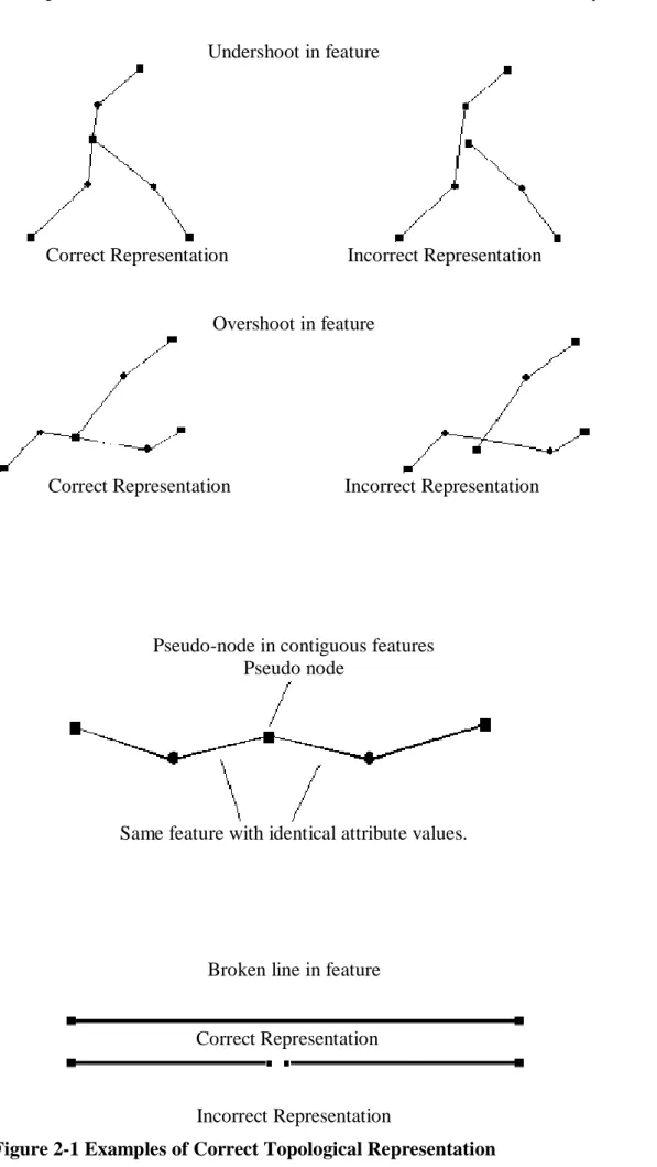
2.13 Spatial Integrity of Features - Topology
2.13.1 All data captured or provided for DSRG shall be topologically clean and free of errors. Data shall be corrected for overshoots and undershoots, polygons shall be closed, and slivers removed. Figure 2-1 and Figure 2-2 provide examples on how correct topology shall be applied.
2.13.2 Topologically clean data allows users to link attributes to features more accurately and to undertake various types of spatial analysis within a Geographical Information System. For example, analysis can be undertaken to calculate the area or parameter of a feature automatically, analyse proximity of features to other features, and automatically quantify change over time.
S
ec
ti
o
n
2
G
en
er
al
D
at
a
S
p
ec
if
ic
at
io
n
Undershoot in featureCorrect Representation Incorrect Representation
Overshoot in feature
Correct Representation Incorrect Representation
Pseudo-node in contiguous features Pseudo node
Same feature with identical attribute values.
Broken line in feature
Incorrect Representation
Figure 2-1 Examples of Correct Topological Representation Correct Representation
S
ec
ti
o
n
2
G
en
er
al
D
at
a
S
p
ec
if
ic
at
io
n
ArtefactsCorrect Intersection Incorrect Intersection Incorrect Intersection
Linear Feature Spike in Linear Feature
Incorrect Representation Correct Representation Figure 2-2 Examples of Correct Topological Representation
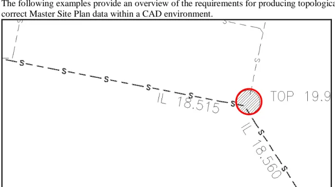
2.14 Spatial Integrity of Features – Topology in a CAD Environment
The following information will assist in maintaining topologically clean data in a CAD environment.
Poly-lines (polygons) close – their start and end points are the same; Line features join or snap together – they share endpoints;
Line feature vertices can also join with point features – they share nodes; Point features provide the vertices for the connecting linework; and Text is associated with the appropriate polygon, line or point feature.
The capturing/editing of the CAD line work will include:
“Snapping” of line/poly-line nodes to appropriate point features; Open Polygon
S
ec
ti
o
n
2
G
en
er
al
D
at
a
S
p
ec
if
ic
at
io
n
“Breaking” utility line work at appropriate point features, e.g. where a pipe/cable connects to above ground features;
Not “Breaking” utility line work where it does not intersect, e.g. where pipes/cables are at different height levels; and Point/Symbol features are represented as a ‘block’.
The following examples provide an overview of the requirements for producing topologically correct Master Site Plan data within a CAD environment.
Figure 2-3 Incorrect Topology - Unconnected line and point features Figure 2-3 shows CAD line features that intersect a point (symbol) feature but the line features do not meet at the node within the point feature.
S
ec
ti
o
n
2
G
en
er
al
D
at
a
S
p
ec
if
ic
at
io
n
The correct topology (Figure 2-4) represents the line features intersecting a point feature by inserting a new vertex to the line and “snapping” it to the insertion point of the point feature. It is assumed that the line feature should be split at the point feature and that the relevant end points of the lines should be at the point feature.
2.15 Data Attributes
2.15.1 Data attributes store descriptive information about particular spatial features within a dataset. Data attributes can include descriptions, dates of capture or update, area, position coordinates, the value of a measurement taken at the location, or a classification or category.
2.15.2 Data attributes are described within the SDMP Detailed Data Specifications within Section 3 onwards for specific types of data.
2.15.3 Where no Specification exists for a data type or where additional attributes are required, the additional attributes shall be reviewed to confirm that there is a clear business requirement. Attributes shall be intuitive to users and shall be allocated intuitive attribute names. Attributes codes and classifications shall follow established industry standards where possible. A description of the business requirements for the information, the attributes and attribute classifications shall be provided within the associated metadata record for the data. If data attributes are provided in an attribute table that is separate to the spatial data then a Unique Identifier shall be included in both the spatial data and the attribute table to enable the spatial features and attributes to be linked.
2.16 Imagery Management – Image Tiling
2.16.1 Digital ortho imagery and LiDAR data are generally ‘tiled’ (divided into smaller images) to manage file size.
2.16.2 It is recommended that the tiling process is undertaken by the data provider. It is also recommended that the data is delivered in both an uncompressed and compressed format.
2.16.3 The recommended tile size to the pixel resolution or Ground Sample Distance (GSD) is detailed in Table 2-3, in all cases the uncompressed file size should be under 300Mb.
Table 2-3 Recommended Tile Sizes Pixel resolution (GSD) (m) Tile size (km) 0.05 0.5 x 0.5 0.1 1 x 1 0.2 2 x 2 0.5 5 x 5
2.16.4 A tile layout dataset or diagram shall be supplied. It is recommended that a layout is provided in GIS format to allow it to be overlaid with the tiled images.
S
ec
ti
o
n
2
G
en
er
al
D
at
a
S
p
ec
if
ic
at
io
n
2.16.5 It is recommended that for most users images are used in compressed formats. Imagery files in excess of 300mb on standard PCs will result in slow display rates. There are numerous proprietary software programs available that can be used to tile or compress data. These include ERDAS Imagine and ERmapper.
2.16.6 Digital imagery file size can be reduced by applying a compression algorithm. The compression ratio can be varied, however the greater the compression the more the quality of the image will be degraded. There are lossless image compressions algorithms available, but the amount of compression is limited. In most cases it is recommended that files are compressed to no more than a 10:1 ratio.
2.16.7 Tile File Names
2.16.7.1 The naming convention for tiles cut from a large data is generally based on the co-ordinates values of the lower left corner of the tile. This can be amended, as required, for smaller tiles.
EXAMPLE: Lower left corner: 298000E 6230000N Tile Name: 2986230
2.16.7.2 If appropriate additional information can be added to the tile name e.g. M6298623010110 where: M=MGA 6=Zone 56 298=Easting 6230=Northing 1=0.1m resolution 01=January 10=2010
2.16.7.3 Tile metadata should record the following information in addition to DSRG Standard Metadata requirements:
Release version; Area of tile; Date flown;
Camera/sensor type; Photo scale;
Image Resolution; and
S
ec
ti
o
n
2
G
en
er
al
D
at
a
S
p
ec
if
ic
at
io
n
2.17 Hardcopy Archival2.17.1 Where electronic documents do not exist and hardcopy files are to be scanned for archival, the following requirements shall apply unless otherwise specified in the Statement of Work:
The plans shall be scanned at a minimum of 200dpi;
Raster images shall be saved as compressed tiff images (LZW compression); Any colour plans shall be scanned as 24 bit jpeg images;
Images shall be cropped to minimum plan extents; Images shall be rotated where necessary;
Skewed images shall be de-skewed (original dyelines may not be straight); and Poor quality originals shall be enhanced (de-speckled and/or sharpened). 2.18 Vectorisation of Information
Vectorisation of hardcopy information and/or electronic images has been undertaken by Defence in the past to capture vector features relating to Defence Properties. Vectorisation of information is not recommended due to the low return on the financial investment and should only be undertaken for a specific business purpose where the financial value of undertaking the work is greater than the cost of
S
p
ec
ia
li
se
d
D
at
a
S
p
ec
if
ic
at
io
n
s
S
ec
ti
o
n
3
–
M
as
te
r
S
it
e
P
la
n
D
at
as
et
S
p
ec
ia
li
se
d
D
at
a
S
p
ec
if
ic
at
io
n
s
S
ec
ti
o
n
3
–
M
as
te
r
S
it
e
P
la
n
D
at
as
et
SPECIALISED DATA SPECIFICATION
Specialised Data Specifications have been created to document standards for specific types of spatial data that have requirements that may differ from, or be additional, to the General Data Specification in Section 2. The Specialised Data Specifications provide more detailed
information relating to the requirements for specific types of data and how the specification should be implemented.
The Specialised Data Specifications contained within the SDMP are listed below:
3 Master Site Plan Datasets 29
4 Spaces Plans 34
5 Reference Data 47
6 Engineering Detail Survey for Infrastructure and Assets 51
7 Garrison Support Services Data 56
8 Communications Data 61
9 Aerial Photography 69
10 Satellite Imagery 78
11 Master Planning Datasets 84
12 Contaminated Sites Data 88
13 Environmental Data 92
S
p
ec
ia
li
se
d
D
at
a
S
p
ec
if
ic
at
io
n
s
S
ec
ti
o
n
3
–
M
as
te
r
S
it
e
P
la
n
D
at
as
et
Specialised Data Specifications
Section 3 – Master Site Plan Dataset
S
p
ec
ia
li
se
d
D
at
a
S
p
ec
if
ic
at
io
n
s
S
ec
ti
o
n
3
–
M
as
te
r
S
it
e
P
la
n
D
at
as
et
3 MASTER SITE PLAN DATASETS
3.1 Scope of Specification
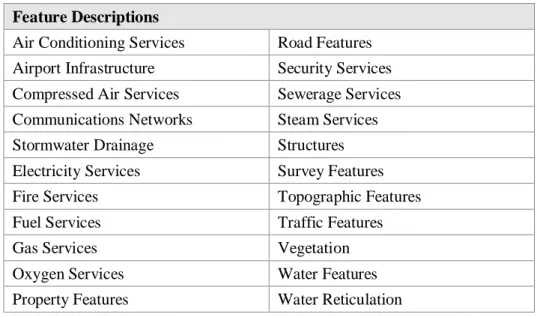
3.1.1 The specification covers the capture and update of the Master Site Plan Dataset that DSRG collects for Defence Properties. The Master Site Plan Dataset stores the position of infrastructure and asset features as listed in Table 3-1 and is a DSRG Key (or Foundation) Spatial Dataset upon which other spatial data is developed and referenced. This specification will be used when a Major or Minor Work or Activity Request has been issued to update a Master Site Plan Dataset.
Table 3-1 Scope of Master Site Plan Data Feature Descriptions
Air Conditioning Services Road Features
Airport Infrastructure Security Services
Compressed Air Services Sewerage Services
Communications Networks Steam Services
Stormwater Drainage Structures
Electricity Services Survey Features
Fire Services Topographic Features
Fuel Services Traffic Features
Gas Services Vegetation
Oxygen Services Water Features
Property Features Water Reticulation
3.1.2 This dataset is used to manage and maintain existing infrastructure, to plan and design new infrastructure on properties, and as a basis for the capture of garrison support services data. A sample of data from a Master Site Plan Dataset is shown in Figure 3-1.
S
p
ec
ia
li
se
d
D
at
a
S
p
ec
if
ic
at
io
n
s
S
ec
ti
o
n
3
–
M
as
te
r
S
it
e
P
la
n
D
at
as
et
3.1.3 The Master Site Plan data is collated from as-constructed design drawings or through Engineering Detail Survey and is accurate to ±0.05 m. A high level of accuracy is required for this data to be used as a base for the design of new infrastructure or services on Defence Properties. To maintain the integrity of the data source the Master Site Plan Dataset must be updated to remain current and must be collected to the nominated accuracy.
3.2 Deliverables
3.2.1 The following deliverables shall be provided:
A dataset containing Master Site Plan data for all features that have been created or updated. A separate dataset shall be created for each Defence Property.
Metadata record for each Master Site Plan Dataset. 3.3 Deliverable Templates
3.3.1 A dataset template in AutoCAD and an AutoCAD file containing sample data is available on the Defence Estate Quality Management Systemat the following location: http://www.defence.gov.au/estatemanagement/Default.asp
3.4 Data Deliverable Specification 3.4.1 Data Format
3.4.1.1 Data shall be delivered in either:
AutoCAD Drawing format. A detailed data specification is documented in Appendix G respectively. It is recommended that the deliverable templates are used as the basis of creating Master Site Plan Data.
An alternate GIS data format is currently being developed. Users wishing to utilise this data format should contact the DSRG Spatial Data Technical Authority.
3.4.2 Data Accuracy
3.4.2.1 The Master Site Plan Dataset shall have a horizontal and vertical accuracy of ±0.05 m.
3.4.3 Engineering Detail Survey – Data Capture Requirements
3.4.3.1 Detail survey shall include all significant infrastructure and asset features from the building line out.
3.4.3.2 Structures and buildings capture shall include the external walls of the building, the roofline and the height of the roofline shall be captured.
S
p
ec
ia
li
se
d
D
at
a
S
p
ec
if
ic
at
io
n
s
S
ec
ti
o
n
3
–
M
as
te
r
S
it
e
P
la
n
D
at
as
et
3.4.3.3 Kerbs capture shall include the kerb profile, top and lip levels at tangent points, changes of direction and grade, and changes in kerb type shall be captured. Maximum 25 m intervals on straights and large radius bends, and at nominal 5 m intervals on small radius bends.
3.4.3.4 Storm water and sewerage capture shall include manhole surface shape, perimeter levels and invert levels, and the size and direction of pipes shall be captured. Any change in direction of the pipes shall be recorded.
3.4.3.5 Underground Cables / Conduits capture shall include a single polyline which shall be used to delineate the location of the cables and shall include any change in direction.
3.4.3.6 Concrete lined drains and other surface drainage structures e.g. drop structures capture shall include detail survey at 25 m intervals for long runs.
3.4.3.7 Road furniture and line-marking capture shall include edge lines to define existing carriageway widths.
3.4.3.8 Trees with a trunk diameter greater than 0.2 m shall be located and the type, trunk diameter and the spread defined. The diameter of the trunk shall be measured 1 m above natural surface level. Trees shall be represented to scale, with spot heights, diameter, species and height to be shown as text in the drawing.
3.4.3.9 Readily observed information regarding features and services shall be noted such as the size/diameter of culverts and lines between power poles.
3.5 Specific Data Requirements
3.6 Topology Specifications – For Information Only
3.6.1 Data must be captured so that it can be used within a GIS topological model of points, lines, and polygons that can then be linked to a database.
3.6.2 The SDMP specifications were initially designed to meet CAD software requirements where the data and information is designed to provide a detailed drawing providing a good picture (rendering) of the data. Although the data and information in a CAD file consist of symbols, points, lines, and poly-lines these elements are referred to as simple features and do not have any topology or link to a database.
3.6.3 A topologically structured GIS supports feature (object) relationships which enables the GIS to perform advanced analysis of the data such as determining the best route from point A to point B as is commonly performed by in-car navigation systems. Capturing data using the topology specifications will support the ability to
S
p
ec
ia
li
se
d
D
at
a
S
p
ec
if
ic
at
io
n
s
S
ec
ti
o
n
3
–
M
as
te
r
S
it
e
P
la
n
D
at
as
et
perform spatial analysis (network analysis) on connecting or adjacent features such as points, lines and polygons.
3.7 Topology Guidelines
3.7.1 The following features shall be collected in accordance with the topology requirements defined within Section 2 of this document.
Polygons: Buildings Linework:
Storm Water/Drainage Sewage pipelines Water Supply pipelines Communication cables Electricity cables Gas pipeline Fuel pipelines Fire water pipelines Points related to:
Storm Water/Drainage Sewage Water Supply Communications Electricity Gas Fuel
Fire water infrastructure Text related to:
Storm Water/Drainage Sewage Water Supply Communications Electricity Gas Fuel
S
p
ec
ia
li
se
d
D
at
a
S
p
ec
if
ic
at
io
n
s
S
ec
ti
o
n
4
–
S
p
ac
es
P
la
n
D
at
as
et
Specialised Data Specifications
Section 4 – Spaces Plan Dataset
S
p
ec
ia
li
se
d
D
at
a
S
p
ec
if
ic
at
io
n
s
S
ec
ti
o
n
4
–
S
p
ac
es
P
la
n
D
at
as
et
4 SPACES PLANS 4.1 Scope of Specification4.1.1 The specification outlines the convention DSRG has adopted for the capture of data for the Spaces Plan Dataset. The Spaces Plan Dataset, or Floor Plan Dataset, is created for all key Defence Buildings and is distinct from an architectural floor plan in that it only shows the size, shape layout and identification number of spaces and rooms within Defence Buildings, door openings, staircases and fittings. The Spaces Plan Dataset is a DSRG Key or Foundation Dataset upon which other DSRG data is based. This specification will be used when a Major or Minor Work or Activity Request has been issued to update a Spaces Plan Dataset.
4.1.2 Where an existing building has a numbering schema in place, that numbering should be adopted.
4.1.3 The data captured is used to assist building management through the allotment of rooms, management of information technology assets, cleaning services, and changes to buildings. A sample of data from a Spaces Plan Dataset is shown in Figure 4-1.
Figure 4-1 Spaces Plan Dataset - example data
4.1.4 The Spaces Plan Dataset is collated from as-constructed design drawings, or through measurement survey, and is accurate to ±0.05 m. This accuracy is required for this data to be used as a base for the design of new infrastructure or services on Defence Properties, and to provide data for future calculation to evaluate net return on assets. To maintain the integrity of the data source the Spaces Plan Dataset must be updated to remain current and must be collected to the nominated accuracy. 4.1.5 The Spaces Plan Dataset shall be updated, if any space or space number is
changed, within 60 days of the change occurring.
4.1.6 Information stored within each Spaces Floor Plan Dataset includes fixed or static elements such as external and internal wall outlines, doorways, voids, core areas, wet areas, corridors, foyers, open spaces and undercrofts. The plans include columns, glazing and other openings (as a line or outline). A list of elements that