Chunying Zhao, Jun Kong, and Kang Zhang,
Senior Member,
IEEE
Abstract—Discovering program behaviors and functionalities can ease program comprehension and verification. Existing program analysis approaches have used text mining algorithms to infer behavior patterns or formal models from program execution. When one tries to identify the hierarchical composition of a program behavior at different abstraction levels, textual descriptions are not informative and expressive enough. To address this, we present a semi-automatic graph grammar approach to retrieving the hierarchical structure of the program behavior. The hierarchical structure is built on recurring substructures in a bottom-up fashion. We formulate the behavior discovery and verification problem as a graph grammar induction and parsing problem, i.e., automatically iteratively mining qualified patterns and then constructing graph rewriting rules. Furthermore, using the induced grammar to parse the behavioral structure of a new program could verify if the program has the same behavioral properties specified by the grammar. Index Terms—Visual language, graph grammar induction, program comprehension, reengineering.
Ç
1
I
NTRODUCTIONW
ITHthe wide deployment of software systems, soft-ware maintenance has become a challenging and costly task [41] due to increasing software size and complexity, incomplete and incorrect documentation, etc. Software maintainers usually need to understand a system before making changes. Studies [42] have shown that 50 percent of a maintainer’s time is spent on understanding the system to be maintained. Effective reverse engineering tools can facilitate this practice [9]. As defined by Chikosky and Cross [9], reverse engineering isthe process of analyzing a subject system to 1) identify the system’s components and their interrelationships and 2) create representations of the system in another form or at a higher level of abstraction. Discovering a program’s structure/behavior and representing them appro-priately have been major challenges in reverse engineering.Since the first generation of software systems, many techniques and tools have been developed for mining program structures and specifications. Some previous work has focused on discovering static program architectures, e.g., mining high-level similarity patterns in a program [6]. Others have aimed at revealing software dynamic behavior [22] by recovering functionalities [25], [38] and locating runtime bugs [11], [47]. There are also considerable efforts on automatically mining software specifications [1], [10], [44], e.g., inferring user-system interaction patterns [48]. Existing methods [37], [48], [49], [53] have reflected a clear trend toward combining machine learning and statistics
techniques, such as clustering and frequent pattern mining, with domain knowledge of software engineering.
In addition to traditional data mining approaches, noticeable achievements have been made on mining program behavior and specifications by grammar/automata inference algorithms [17], [19], [46]. A foundation research on behavior mining proposed by Cook and Wolf [17] uses event data in the form of an event stream, collected from program execution, to infer a formal behavioral model. They cast the behavior discovery issue as the problem of constructing a grammar from given example sentences in that language [17]. The resulting grammar rules form a hierarchical lattice. Another pioneering work on specifica-tion mining [1] generates specificaspecifica-tions about program behavior models by inferring probabilistic finite-state auto-mata from program execution traces. The transitions and system states in the automata represent clustered events occurring more frequently.
The above approaches, however, are built based on formal methods which require a deep learning curve and domain knowledge for maintainers to comprehend. To alleviate the cognitive loads, an integration of sophisticated structure mining algorithms with visual representations is desirable to fill the gap between expert practice and users’ comprehension. Being extensively used, visual program-ming languages have been recognized effective in software modeling and specifications [43], e.g., UML diagrams. A visual language [20], [21], [35] is formed by a set of visual sentences over a set of visual symbols from an alphabet, and the spatial arrangement of the visual symbols obeys the syntax of that language [14]. Graph grammars, the founda-tion of visual languages, can precisely specify the syntactic and semantic information in multidimensions with dia-grammatical structures. With supporting visual program-ming environments [12], [40], [47], [57], [60], developers can benefit from a graph grammar’s formal specifications and expressiveness in visually representing information.
As an enhancement to previous text-based automata/ grammar inference approaches, this paper addresses the . C. Zhao and K. Zhang are with the Department of Computer Science,
University of Texas at Dallas, Richardson, TX 75080. E-mail: {cxz051000, kzhang}@utdallas.edu.
. J. Kong is with the Department of Computer Science, North Dakota State University, 258 IACC #2740, 1320 Albrecht Blvd., Fargo, ND 58102. E-mail: [email protected].
Manuscript received 8 Feb. 2009; revised 12 Sept. 2009; accepted 30 Nov. 2009; published online 8 Jan. 2010.
Recommended for acceptance by H. Schmidt.
For information on obtaining reprints of this article, please send e-mail to: [email protected], and reference IEEECS Log Number TSE-2009-02-0029. Digital Object Identifier no. 10.1109/TSE.2010.3.
program behavior mining and verification problem from a visual language perspective using graph grammar induc-tion and parsing techniques. We exploit the power of a graph grammar in specifying information visually with a precise meaning. More especially, method calls in the execution trace of a program can be naturally represented as a graph in which nodes represent methods and edges indicate method calls. Given such a graph, searching for frequent calling patterns assists in discovering the behavior of a program [54]. When the call graph is considered as a visual sentence, the discovery process is essentially a grammar induction. Integrating graph grammar with grammar induction can support an automatic analysis of a program behavior. The result with a visual presentation can improve user comprehension with a precise meaning.
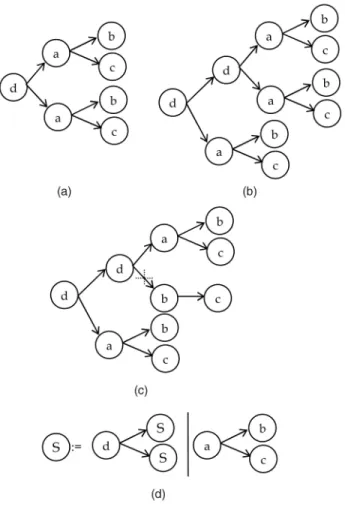
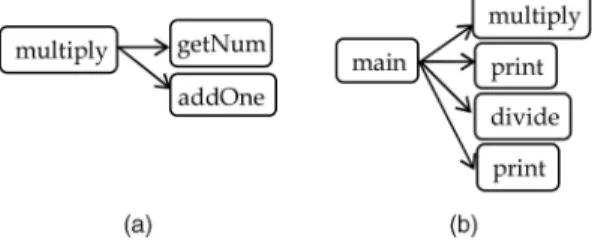
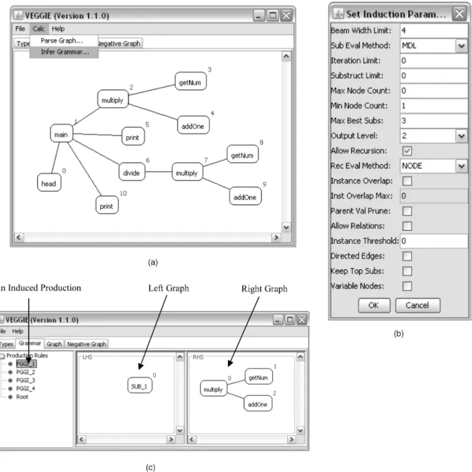
As a motivating example, Fig. 1a depicts a simple call graph of a program. The call graph represents the behavioral structure when the program executes certain functionalities. The graph consists of two common substructures:a-b-c. We apply a graph grammar induction algorithm on the call graph and then generate a graph grammar as depicted in Fig. 1d. The syntax of the grammar represents the behavioral properties of that program.
Apart from comprehension, we can use the induced grammar for program behavior verification. The formal specification of a graph grammar is capable of checking the syntactic correctness of a call graph by parsing, i.e., verifying if the behavior of a program observes the
properties specified by the grammar. Source code realizing certain functionality could be reused for different programs. Therefore, programs may have similar behavioral proper-ties when they execute similar functionaliproper-ties. For instance, if developers want to check whether a new program has the same behavior with the old one, he/she can parse the new program with the graph grammar inferred from the old program. A valid parsing result means that the new program satisfies the same behavioral properties as the old program. Consequently, two types of behavior verifica-tion can be performed [55]:
. verify acceptable call sequences in a scenario and . detect illegal behaviors or security-related activities,
such as access control.
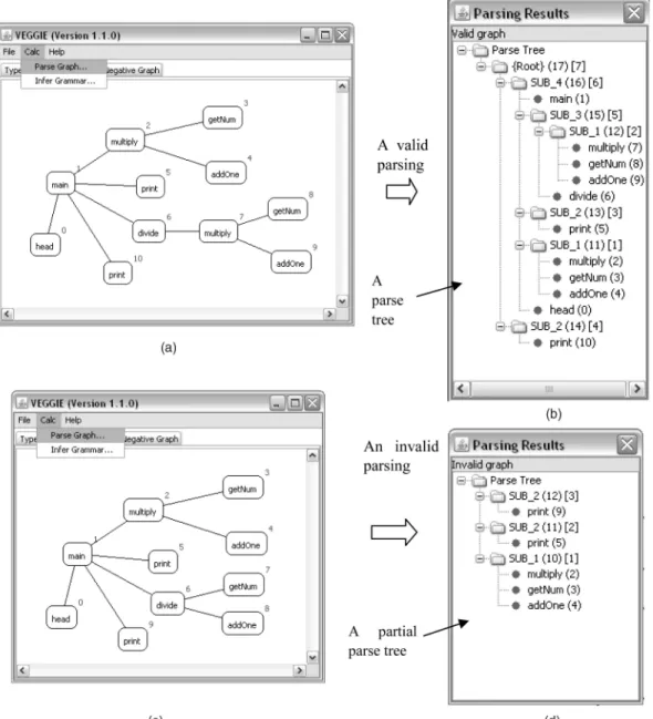
Using the induced graph grammar in Fig. 1d, we can check if the call graphs in Fig. 1b and Fig. 1c satisfy the structural properties specified by the grammar. A valid parsing result will be generated for Fig. 1b. Therefore, we can conclude that the graph in Fig. 1b maintains the behavior properties specified by the induced grammar. However, Fig. 1c cannot be parsed successfully due to an erroneous method call fromdtob. To automate the whole process of graph grammar induction and parsing corre-sponding to behavioral structure mining and verification, we use a visual programming environment called VEGGIE [2], [3], theVisual Environment for Graph Grammars: Induction and Engineering.
The rest of the paper is organized as follows: Section 2 is an overview of our approach. Section 3 introduces pre-liminary concepts of visual languages, including graph grammars, grammar induction, and parsing. Section 4 provides detailed specifications of our approach. Section 5 presents the architecture and usage of a visual environment. Section 6 describes experiments on an open-source project and discusses the empirical results. Section 7 reviews related work, and finally, Section 8 concludes the paper.
2
A
PPROACHO
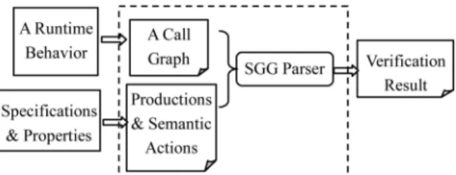
VERVIEWFig. 2 depicts the approach overview. The graph-grammar-based approach essentially consists of two major function-alities: behavioral structure discovery and behavior verifica-tion. We use Abstracer [56], a multicriteria trace abstraction tool, to construct and trim call graphs from program execution traces. Then we use VEGGIE [2], [3] to infer recurring structures from observed program execution, and finally, verify the program with expected properties.
VEGGIE, initially designed for graph grammar induction and parsing, essentially incorporates two subsystems: Sub-dueGL [28], [30] and Spatial Graph Grammar (SGG) [31], [32]. The former is a graph grammar induction system for mining recurring behavioral patterns from execution traces. The latter is a graph grammar formalism with an efficient parser that we use for checking whether an observed behavior in a call graph satisfies the design specifications expressed in the graph grammar.
The upper flow in Fig. 2 describes a behavior discovery process. We first run a program under study together with instrumentation code implemented with AspectJ [29]. AspectJ is an aspect-oriented extension to Java.
Instrumentation aspects are automatically woven with Java byte code during compilation instead of being inserted into the source code, which is less intrusive to the original system. Then, execution traces of method invocations are collected during program execution. We construct call graphs from the execution traces using Abstracer and then abstract the call graph based on abstraction criteria [56]. Abstracer removes execution traces that play less significant roles in representing the program behavior and then represents the abstracted call graph in GraphML [58]. The abstracted call graph is the input to the grammar induction engine of VEGGIE. VEGGIE can automatically derive a set of graph rewriting rules from a given graph using a compression-based substructure mining algorithm. Additionally, an expert can also manu-ally draw or modify the grammar in the Grammar Editor of VEGGIE. The induced grammar represents the hierarchical structure of the program’s behavior.
The lower part of Fig. 2 describes a behavior verification process. A graph grammar (either automatically induced or manually designed) is used as specifications to verify the valid behavioral properties, e.g., valid call sequences of methods. Based on the graph grammar, we can check whether the given instance graph satisfies the properties specified by that grammar. With a valid parsing, a parse tree representing the composition of the input program behavior will be generated and visually displayed to the user.
In the current implementation, we use call graphs to represent program behavior and apply the induction and parsing on the call graphs. The approach is general enough to discover and verify other program structural properties.
3
G
RAPHG
RAMMARS ANDT
HEIRP
ARSINGGraph grammars extend Chomsky’s generative grammars into the domain of graphs by using diagrammatic and graphical structures, such as boxes and arrowed lines. In a graph grammar, a graphGis denoted by a tuple<N; E>, whereN is a set of nodes andENN is a set of edges in the graph. A graph rewriting rule, also called produc-tion, consists of aleft graphand aright graph. A production is in the format of S:¼P1jP2. . ., in which both S and Pi
are graphs.
This paper uses the SGG [31], [32] formalism. SGG is context-sensitive graph grammar formalism, which sup-ports an arbitrary number of nodes in both the left and right graphs in a production. Therefore, SGG is adequate to specify program behavioral properties in call graphs, e.g., valid call sequences. SGG is expressed in a node-edge
format. Nodes are organized into a two-level hierarchy, where a large rectangle representing the node itself is the first level with embedded small rectangles at the second level calledvertices.
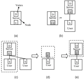
Fig. 3a depicts a typical SGG node including two vertices. In a node, each vertex is uniquely labeled. A node can be viewed as a module, a procedure, or a variable, depending on the design requirements and data granularities. A vertex functions as a port to connect other nodes by edges. Edges can denote any type of commu-nications or relationships between nodes. Fig. 3b depicts an SGG production.
SGG uses a marking technique [32], [51] to address the embedding issue, i.e., building connections between a replacing subgraph and the surrounding of a replaced subgraph, during subgraph replacement. In a production, a vertex is marked by prefixing its label with a unique integer. For example, in the above production of Fig. 3b, vertexUof the nodeServeris marked, while vertexDis unmarked. If a vertexvin a replaced subgraph maps to a marked vertex,v
will be preserved during graph transformation to establish connections between the surrounding of a replaced sub-graph and a new subsub-graph. Fig. 3c shows an isomorphic subgraph (in the dotted rectangle) corresponding to the right graph of the production in Fig. 3b, and the vertex with gray background maps to the marked vertex. The gray vertex will be preserved in a graph transformation, as shown in Fig. 3d, and the transformed graph is shown in Fig. 3e.
Fig. 3. Spatial graph grammar. (a) A node. (b) A production. (c) Before transformation. (d) Preserve context information. (e) After transformation. Fig. 2. Approach overview.
Graph grammar induction and parsing are two core concepts in visual languages. Grammar induction, also known asgrammatical inference, is defined as [17]:
Given some sample sentences in a language, and perhaps some sentences specifically not in that language, infer a grammar that represents the language.
A graph grammar induction algorithm iteratively finds common substructures from the given graph and organizes the hierarchical substructures in a grammatical form. When a common frequent substructure is found, a production will be created. The substructure consisting of terminal and nonterminal symbols identified from the graph is repre-sented as the right graph of the production, and new nonterminal symbols will be created as the left graph. Then, the new production will be applied to the current data set. In other words, a substructure matching that of theright graph will be replaced by theleft graph. The procedure ofpattern mining—production creation—substructure replacementwill be recursively performed on the original graph until there are only nonterminal symbols, or a threshold (i.e., a stop criterion defined by the user) is reached. Graph grammar induction could apply to many standard graphical repre-sentations, e.g., call graphs and dependency graphs.
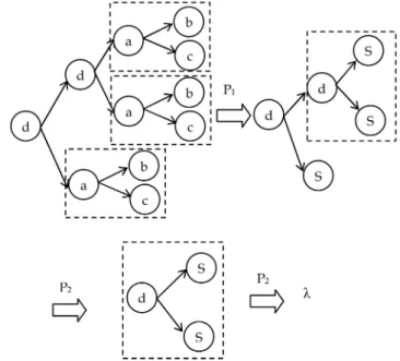
Fig. 4 depicts a grammar induction process applied on the call graph (see Fig. 1a). In each iteration, a production is created.
Graph grammar parsing is to verify the membership of a graph in a language. If a given graph, typically called ahost graph, is eventually transformed into an initial graph, the parsing process is successful and the graph is considered to satisfy the structural properties specified by the graph grammar. Fig. 5 depicts a parsing process on the host graph in Fig. 1b based on the grammar in Fig. 1d.
Grammar parsing has been used in checking software design. One successful example in software engineering is design pattern discovery [13], in which the structure of a design pattern is encoded as a grammar. By parsing a given UML class diagram with the grammar, the user can identify and verify the existence of a design pattern. Such a parsing process when applied to behavior verification can check the
behavioral structure of the given program and reveal the hidden hierarchical composition of that program behavior. The time complexity of the SGG parser is critical to the overall system performance. The SGG parser uses efficient string matching technique, instead of graph matching, to search for an appropriate substructure that matches the right graph of a production. SGG parser is developed based on confluent graph grammars. Informally, the confluence requires that different orders of applications of productions achieve the same result, and therefore, the parsing only tries one parsing path. Under the confluence condition, the SGG parser has a polynomial time complexity [32].
4
P
ROGRAMI
NDUCTION ANDV
ERIFICATIONThis section first describes the program behavior models and then discusses our approach in detail, including trace processing, behavior discovery, and behavior verification.
4.1 Program Behavior Model
Scenarios can be derived from an execution trace based on causalrelationships. Causality characterizes the interactions between events, i.e., a causal order between methods. Fig. 6 presents three objects in whichei represents a method. A
directed edge from ei to ej means that method ei calls Fig. 4. A grammar induction process.
Fig. 5. A grammar parsing process.
methodej. Such a calling relation indicates a causal relation
betweenei andej.
Definition 1.If a methode1(i.e., the caller) calls another methode2
(i.e., the callee), there is a causal relationship between e1and e2, denoted bye1!e2.
Definition 2. A causal link l is an ordered set of methods
E¼ fe1; e2;. . .; emg, whereei!eiþ1,0< i < m.
For instance, in Fig. 6,e1!e3!e4!e5 ande1!e3! e4!e6!e7!e8 form two causal links. Due to the
transitivity of causality, any two methods in a causal link are of a causal relationship, e.g.,e1!e4is true.
Definition 3.A scenarioSconsists of a set of causal linksL= {l1; l2;. . .; ln}, where 8li; lj2L;9ek2E¼e1; e2;. . .; ep;
li\lj¼ek (0< i; jnand0< kp).
The execution trace generated from an instrumented program provides the clue to the discovery of causal links in a scenario diagram. Since we record the enter-exit of method invocations, the nested enter-exit relations in method calls reveal the calling relationships between methods. Fig. 7 depicts a method invocation. A causal relationshipA:m!B:ncan be derived from the trace:enter A.m—enter B.n—exit B.n—exit A.m.
A scenario model could guide the reasoning about object interactions from execution traces and provide a foundation to define program behavioral specifications. Based on the causality of methods in a scenario, we can derive several properties. These properties are the basic conditions to ensure the correctness of a scenario.
Property 1. The causal links in a traced scenario are connected, i.e., each causal link must share at least one node with another link in the same scenario. Disjoint links could be directly initiated by separate external events, such as a user interaction. This property ensures that events in a scenario are connected through causality such that every event has at least an internal or external initiating event.
Property 2.A scenario is cycle-free, i.e., no causal link can form a cycle.
For instance, a link e1! :!ei! :!ei!ej!
:is an illegal scenario in which a cycle exists.
The program behavior is represented as a call graph to be parsed in the grammar system. Specifications of the proper-ties in the program behavior are represented as productions. More formally, a call graph is a tuple G¼<N; V ; E; L; s; t; f>, where
. N is a set of nodes. . V is a set of vertices inN.
. Eis a set of edges.
. Lis a set of labels of the nodes, vertices, and edges. . s:E!V and t:E!V are two functions that specify the source and target vertices of each edge. . f:E[V [N !L is a function assigning labels to
nodes, vertices, and edges.
A graph grammar representing program behavioral properties is defined as a tupleG¼<T ; N; E; P >, where
. P is a finite set of productions specifying the behavior properties, e.g., acceptable valid sequences of method invocations with certain constraints satisfied.
. T is a finite set of terminal nodes inP, representing methods occurring in the scenario.
. N is a finite set of nonterminal nodes inP.
. E is a finite set of edges in P, connecting callers and callees.
4.2 Trace Preprocessing
Many trace collection approaches insert additional codes to the original program to record execution traces. Developers have to prune the inserted codes from the original program after instrumentation, which is usually error-prone. To obtain execution traces, we have implemented an aspect-oriented instrumentation approach instead of putting extra tracing codes into the original system. Using AspectJ [29], instrumentation aspects are created and seamlessly com-piled with Java byte code.
AspectJ modularizes the concern of a user’s interest tangled in a complex system. The modularized crosscutting concern is called an aspect. To define an instrumentation aspect using AspectJ, we need to declare 1)join points(i.e., the specific points in the execution of the program), 2)pointcuts(i.e., the collection of join points), and 3) advice (i.e., the piece of code that is executed when a pointcut is reached). In the current implementation, the following informations are recorded for each method invocation:
. names of classes, objects, and methods,
. method invocation: enter-exit of every static or nonstatic method.
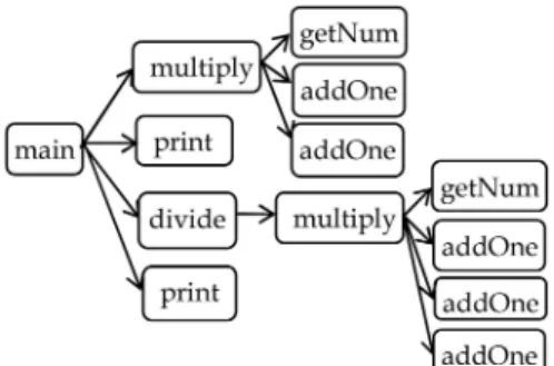
Fig. 8 depicts a call graph of a toy program. Intuitively, data traced from a running program record the actual behavior of the program. For each scenario, we build a call graph based on the program behavior model, and then an abstraction and behavior induction/verification process is performed on this call graph. Initially, the call graph is
Fig. 7. A method call.
implemented as a linked list. Each caller maintains a pointer to each of its callees. To be compatible with the data format in the induction and verification systems, call graphs are represented in GraphML [58]. The information of objects and method invocations corresponds to the GraphML syntax, such as elements, attributes, nodes, and edges.
A data processor calledAbstraceris built for tracing the system under study. It produces logs, reduces redundant and noise traces with tunable parameters, and generates GraphML files. Following the GraphML syntax, we represent caller-callee relationships in schemas, where method invocations are denoted by a node-edge format. Each node representing a caller or a callee has a unique integer id, a type for its name, and a position in the VEGGIE’s Graph Editor. Method names are included in the corresponding nodes’ attributes. Similarly to the edges in call graphs, each edge in GraphML representing a method invocation is directed, and explicitly connects a starting node (a caller) to an ending node (a callee).
A GraphML example for a method invocation “main! multiply” is shown as follows:
<?xml version = “1.0” encoding = “UTF-8”?> <!- - SGG Graph Data - ->
<graphml xmlns =
http://graphml.graphdrawing.org/xmlns> <graph edgedefault = “directed” xmlns =
http://viscomp.utdallas.edu/VEGGIE>
<node id = “1” type = “main” pos = “995 945”> <port id = “{main}”/>
<data key = “attrib”>
<attrib id = “Terminal” type = “2” bool = “true”/>
</data> </node>
<node id = “2” type = “multiply” pos = “878 252”> <port id = “{multiply}”/>
<data key = “attrib”>
<attrib id = “Terminal” type = “2” bool = “true”/>
</data> </node>
<edgetype = “E” directed = “true” source = “1” target = “2” sourceport = “{main}” targetport = “{multiply}”/>
</graph> </graphml>
When analyzing program execution, developers are usually overwhelmed by the large volumes of the execution traces, which prevent effective mining and verification. Thus, we need to abstract and simplify the trace by eliminating information that contributes little to the program behavioral structure. To achieve this goal, the following criteria have been developed to prune an execution trace:
. continuous repetitions, . low-level methods.
The first abstraction criterion aims at reducing possible redundant traces. Loop is one of the major sources causing redundant information. In our approach, a loop is
represented as one instance with a repetition number. Eliminating the redundant or fine-grained structures can help the induction process to focus on high-level behavior. It can also avoid mining redundant behavior. Fig. 9a shows an abstracted graph after removing the loop on method addOne in Fig. 8. In order to eliminate low-level details, our approach allows a user to specify a threshold. If a method has a call depth that is greater than the user-specified threshold in a call chain, this method is pruned. For instance, if the threshold is set as 2,addOneandgetNum, which have a depth of 3 or more in Fig. 8, are considered to be low-level details with respect tomultiply. The abstracted graph is shown in Fig. 9b. Developers may decide whether to reduce low-level structures or not. Low-level structures are collapsed if a developer is only observing high-level behavior between different objects. Otherwise, they are preserved for a detailed analysis.
The abstraction ensures equivalent behavior semantics between the original call graph and the abstracted one, and allows users to focus on the activities they are interested in. The abstraction on loops and low-level methods satisfies the safe property, meaning that methods in an abstracted scenario comply with the causality properties of the original call graph. In other words, the causal relationship between any two methods in an abstracted scenario S’ remains if there exists a causal relationship between the two methods in the uncompressed scenario S. Therefore, our behavior pattern mining and verification can be performed on abstracted call graphs.
4.3 Assigning Patterns with Temporal Properties
A behavioral pattern describes activities that happen in an order. To reflect this, we assign nodes in a call graph with temporal attributes. Without a temporal order, the inferred common patterns may not be correct even if they are graphically isomorphic. We use logical time stamps to keep track of methods’ order. A sequence method A occurred 5 seconds before method B is considered the same as the sequencemethod A occurred 2 seconds before B.
Each substructure Gis represented as a tuple <N; E>, whereNis a set of nodes andEis a set of edges connecting nodes in the substructure (i.e., subgraph). Each node in the subgraph has one additional attribute:time stamprepresented bytnifor nodeni. The time stamp is generated when the node
is produced. In the GraphML representation, each node in the graph has an integer time stamp. Anode vectorvGrepresents
an ordered sequence of nodes within the substructureG, i.e.,
vt¼n1; n2; n3;. . .; nn, where if i < j, then tni< tnj. This
means thatni happens beforenj. Two substructures G1¼
fN1; E1g and G2¼ fN2; E2g are considered equivalent if
Fig. 9. An abstraction on the call graph in Fig. 8. (a) Reducing loops. (b) Reducing low-level branches.
and only if they are isomorphic and have the same node vector.
The time attribute is considered when grammar induc-tion performs subgraph matching. For instance, two graphs in Fig. 10, where the integers represent logical time stamps, are not equivalent since their node vectors (Multiply, getNum, addOne) and (Multiple, addOne, getNum) are not equivalent.
4.4 Program Behavior Discovery and Verification
Graph grammar induction uses graph-based substructure mining algorithms instead of text mining techniques. A substructure is defined as a representation of recurring subgraphs. An instance is one occurrence of such a substructure in the graph data set. The substructures recognized by the grammar induction procedure reveal hidden recurrent patterns within the graph data set. The hierarchical relations within the grammar can aid the developers in understanding and analyzing the composi-tion of large and complex legacy systems. Those grammars can also be used to build graphs to simulate the execution of a system.
A variety of substructure mining algorithms [27], [33], [34], [45], [49] promotes the development of several graph grammar induction systems [17], [19], [28], [30]. For instance, Li and Zhou [33] used frequent subgraph mining to find substructures. Instead of using frequency, VEGGIE [2], [3] uses a compression-based frequent pattern discovery algorithm (SubdueGL) to identify substructures, and compresses the substructures having the highest compres-sion ratio. VEGGIE emphasizes on the compressing of graph data sets rather than purely searching for the frequent subgraphs. The compression ratio for each sub-structure is calculated based on a minimum description length (MDL), and the substructure with the highest compression ratio among the competing substructures is selected. Therefore, the substructure found in each iteration may not be the most frequent one, but it can achieve the best compression ratio for the given graph, i.e., the ratio between the original and resulting graphs after the subgraphs is replaced with a nonterminal node.
VEGGIE generates candidate substructures and evalu-ates them using the following measure [30]:
sizeðGÞ sizeðSÞ þsizeðG=SÞ;
whereGis the input graph,Sis a substructure, andGjSis the graph derived from Gby replacing each instance of S
with a single node. The size of a substructureSis computed by summing the number of its nodes and edges, i.e.,
sizeðSÞ ¼nodeðSÞ þedgeðSÞ, as a simplified measurement of MDL [16].
By iteratively discovering substructures with the largest compression ratio, VEGGIE replaces subgraphs in a given graph. The iterations ultimately convert the given graph into one or more nonterminal nodes until no qualified substructures exist. Users can also set a threshold for the number of iterations. Multiple compressions on the given graph constitute a structural hierarchical lattice that corresponds to a graph grammar.
A frequency-based pattern mining approach may not necessarily compress the graph best. For instance, the compression ratio of substructures (highlighted in a dotted circle in Fig. 11a), which have size 1 and frequency 3, is less than that of the substructures, which have size 3 and frequency 2 in Fig. 11b. Hence, frequency as used in many previous systems is not always the best factor in graph compression. The beauty of this grammar induction system for behavior discovery lies in its compression capability since it needs the least number of iterations to reduce a graph to the minimum.
VEGGIE provides a graphical user interface to define grammars using diagrammatic symbols. A graph grammar defines all of the acceptable method call sequences in call graphs. Each production is associated with a semanticaction code. Action code is a piece of Java code that is executed when the right graph of the production is applied to a host graph. The architecture of the verification process via graph grammar parsing is shown in Fig. 12.
Considering the scenario in Fig. 13, object A has no authority to access methods in object C, thus object Acan only indirectly invoke a method in object C via some methods of object B. The solid lines depict the legitimate scenario, while the dashed line illustrates an illegal scenario. Both the legal and illegal behaviors can be checked using predefined specifications. Likewise, other types of behaviors such as a missing connection in a causal link and a cycled causal link can also be detected. A legal scenario describes a valid call sequence and an illegal scenario indicates a call sequence which is not supposed to exist in the program behavior.
Fig. 11. Graphs with different reduction ratios.
Fig. 12. Architecture of the verification system. Fig. 10. Two graphs with temporal attributes.
Fig. 14a shows the corresponding productions (P1,P2, and
P3) for the legal behavior. Users can use this set of
productions to automatically verify the behavior of a call graph. A valid parsing result indicates a correct behavior in the verified call graph. Otherwise, the tested program does not satisfy the behavioral properties defined by the grammar. Fig. 14b shows an illegal call graph in which a method in ObjectAdirectly calls a method in ObjectB. Parsing this call graph based on the graph grammar in Fig. 14a results in an invalid result.
5
T
HEVEGGIE S
YSTEM 5.1 Constructing VEGGIEBased on graph grammar formalism, various visual programming environments [36], [40], [52], [57], [60] have been developed to support visual interaction and program-ming. Those systems allow a user to directly manipulate visual objects in a two-dimensional fashion, and have been successfully deployed to model, analyze, simulate software artifacts with a graphical representation [5], [20], [21]. The Visual Environment for Graph Grammars: Induction and Engineering (VEGGIE) [2], [3] improves previous work by incorporating a grammar induction algorithm into a visual programming environment, which reduces the learning curve since a graph grammar can be automatically
produced, instead of being designed manually. Therefore, users do not need to know the formal theories underlying a graph grammar.
Though many efforts have been made on developing various visual language environments supporting grammar construction and parsing, few studies have been conducted on inducing a context-sensitive graph grammar [28]. To our knowledge, there are no tools combining grammar con-struction, graph parsing, and grammar induction in one environment. Developing such a unified system is challen-ging as there are no widely accepted standards and specifications for different visual language environments. Standardizing on a common framework is a goal for developing VEGGIE.
VEGGIE is essentially an integration of the SubdueGL and SGG systems with many novel enhancements. It merges graph grammar induction, grammar construction, and parsing functionalities in a unified system. VEGGIE uses a node-edge representation that can be easily converted to a UML-like presentation [4], which can assist the under-standing of a production due to the popularity of UML.
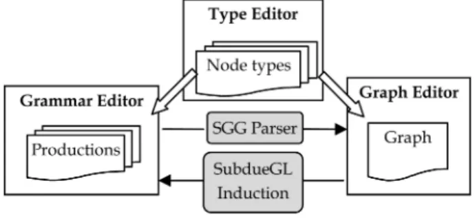
Fig. 15 shows the architecture of VEGGIE. It mainly consists of three independent editors: the Type Editor, the Grammar Editor, and the Graph Editor, and two functional engines: a SubdueGL induction engine and an SGG parser. The three visual editors are closely related and seamlessly working together in VEGGIE. The combined views ease the switching between different editors with a consistent look and feel, which enhances a coherent understanding. The user can either manually create visual objects, i.e., node types, in the Type Editor, or import existing node types. Then with these predefined nodes, the user can create graphs in the Graph Editor or define productions in the Grammar Editor. The data files storing nodes, grammar, and graph are shared and interoperated by all editors. The user can either induce a graph grammar from a host graph in the Graph Editor using the induction engine or parse a given graph with the productions in the Grammar Editor with the SGG parser.
More technical details on the construction of VEGGIE can be found in our previous work [2], [3]. The following sections explain the design specification and usage of each module in VEGGIE.
5.2 Visual Object Generation
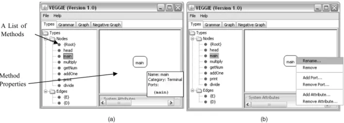
The Type Editor of VEGGIE in Fig. 16 is used to define nodes. It allows developers to specify various properties of a node, such as types, attributes, and ports. On the left panel of the Type Editor, each node denotes a method, and each
Fig. 14. Example productions. (a) A legal call sequence with the corresponding productions. (b) An illegal method call.
Fig. 15. The VEGGIE system. Fig. 13. An example scenario.
edge represents a calling relationship between two meth-ods. The head node is used as a root without any special meaning. To avoid cluttering the display space and confusing the user, in the current version of VEGGIE, we only explicitly display nodes. If the mouse moves over a node, detailed information of the node, e.g., ports (i.e., vertices), will be displayed as depicted in Fig. 16a. The user can select one method from the list. Then the node will be displayed on the right panel. On a selected method, the user can make several modifications, e.g., removing, adding ports, or changing attributes (Fig. 16b).
VEGGIE provides two ways to specify methods. A user can create a visual object, i.e., a round rectangle with a name inside, via “add node type,” as shown in Fig. 17a. After creating all of the nodes, the user can click these nodes and display them on the right panel, and then connect the methods via the “add edges” operation in the Graph Editor. Manually creating a list of nodes is mostly used when the user wants to create productions or graphs manually.
A more efficient way of defining methods in VEGGIE is to import a type file (Fig. 17b), which is automatically generated from a call graph. When we load a graph file representing a call graph to the Graph Editor, VEGGIE will pop up a window for the user to generate a type file from
the graph. By selecting “yes,” the nodes and edges will be generated automatically. If the type file has already been created, the user can import the graph directly and merge new nodes appearing in the graph with existing nodes. Both the type file and graph file are stored in GraphML.
5.3 The Induction Procedure
Fig. 18a shows a call graph in the Graph Editor. In this graph, each edge directs from a node with a smaller integer to a node with a larger integer. The integers associated with nodes specify a temporal order.
TheCalcmenu in the interface provides two actions for end users to perform either grammar induction or grammar parsing on a given graph. By clicking on the command “Infer Grammar,” a parameter-setting window will popup (Fig. 18b). It includes all the parameters for the induction algorithm, such as the iteration limit. Different settings of the parameters may produce different results. Detailed meanings of these parameters can be found elsewhere [3]. After setting the parameters or using the default ones, the user can get the induction results automatically generated by VEGGIE. For instance, VEGGIE derives five productions from the call graph in Fig. 18a. The productions are automatically added to the Grammar Editor as shown in Fig. 18c.
Fig. 16. Modifications on visual objects.
The leftmost panel of the Grammar Editor in Fig. 18c lists all of the productions inferred from the toy program. By clicking on one of the productions, the corresponding details are displayed in the middle and right panels, representing the left graph and right graph of the selected production, respectively. The sequence of the productions indicates the order that the productions are created by the induction algorithm.
For instance, Fig. 18c shows the first graph production inferred by VEGGIE. The right graph of the first production is the first substructure found by the induction algorithm. During the induction process, after replacing the substruc-ture that matches the right graph with the left graph, the induction algorithm begins the next round and then searches for the next substructure. Iteratively, a set of productions is generated. By analyzing these productions, developers can get a sense of the hierarchical structure of the program behavior. Apart from displaying the productions on the
interface of Grammar Editor, the induced productions can be exported and saved in the GraphML format. The saved productions encode the structural properties of call graphs and could be reused for checking the structures of other programs.
5.4 The Parsing Procedure
VEGGIE’s parsing subsystem includes an SGG parser as described before. In addition to the productions automati-cally generated by the VEGGIE’s induction subsystem, the user can define productions on the Grammar Editor following the node-edge specification of SGG. To define a production, users do not have to draw each node and edge. Instead, they can select nodes from a node list, and then define the left graph and right graph of each production.
One can verify the program’s properties by parsing the given call graph using the specified grammar. To realize it, developers can use the parse command in the Graph Editor,
as shown in Fig. 19. Then VEGGIE pops up a window, and reports the verification result: valid or invalid. For a valid host graph, a hierarchical parse tree will be produced. The parse tree illustrates the behavioral structure of a given call graph. If the parsing fails, an invalid parsing result “Invalid Graph” will be generated, with a partial parse tree including only the structures that could be recognized.
Considering the call graph in Fig. 19a, after the user issues the “Parse Graph” command, the given graph will be parsed based on the graph grammar listed in the Grammar Editor. In this example, we used the productions automatically generated by the induction procedure in Fig. 18c. Fig. 19b shows a valid parsing result. The hierarchical parse tree can be collapsed at different abstraction levels. Such a parsing tree reveals behavior patterns underlying a given call graph. Therefore, a user could understand the composition of the given program behavior together with the relationships between the components. In another parsing attempt, we try the same grammar used in the first parsing and a different call graph in Fig. 19c. The second parsing turns to be
unsuccessful and produces an “Invalid graph” result, as depicted in Fig. 19d. The hierarchical structure shows a partial parsing result. A partial parse tree means that the given graph syntactically satisfies only a subset of the productions of that grammar. As the graph represents a program behavior, the result indicates that the program behavior only satisfies part of the structural properties of the specifications. The satisfied portion can be derived from the partial parse tree.
6
E
MPIRICALR
ESULTSWe designed two experiments for program behavior struc-ture discovery and verification using an open-source project JHotDraw [59]. After intercepting the execution traces of drawing activities in JHotDraw and abstracting the traces, we first used VEGGIE to discover the composition of program behavior. Each induced production represents a hidden substructure in the behavior. A parse tree of a call graph reveals the behavioral structure at different abstraction levels.
The second experiment aims at verifying the program behavior based on a graph grammar. We successfully located a program bug that was previously unidentified.
6.1 Open Source Project JHotDraw
JHotDraw is a GUI framework with structured drawing editors written in Java and was initially designed to illustrate the application of design patterns. We use Version 6.0 Beta that contains 136 classes, 1,380 methods, and 19 interfaces.
JHotDraw supports many drawing activities. Commonly occurring activities include the following:
. run JHotDraw and initiate the drawing environment; . create new display view;
. draw graphs such as rectangle and triangle; . start and end animation;
. close JHotDraw, etc.
Using AspectJ, we defined the instrumentation aspect by specifying the pointcut as follows:
execution (* *. * (..)) && ! within (org. lib. instrumentation) && within (org. jhotdraw. samples. *. *).
6.2 Program Behavioral Induction
We designed four scenarios to trace and analyze JHotDraw behavior.
Scenario 1:Draw a rectangle. No abstraction was made on the raw trace. This intends to evaluate the grammar induction ability of identifying structures without abstraction.
Scenario 2: Draw one triangle four times. By applying the first criterion in abstraction process (refer to Section 4.2), we intend to evaluate if the induction can identify the repeating behaviors ofdrawing.
Scenario 3:Draw one triangle four times. We apply the two criteria to abstract the raw execution traces. We intend to compare with Scenario 2, and evaluate the influence of the
abstraction on induction. We used the same raw trace as in Scenario 2.
Scenario 4: draw a triangle and an ellipse, and start and end animation twice. Continuous redundant traces were
Fig. 20. An abstracted graph of scenario 3.
eliminated. This intends to evaluate the inference power on substructures that represent various activities.
Fig. 20 shows the abstracted graphical representation of Scenario 3 after trace reduction. Eight productions are induced from the call graph. The first two productions are shown in Fig. 21. From the productions, we observed that the drawing activity that appears four times in this scenario is identified as the first substructure (i.e., the right graph of Production 1) by VEGGIE, which is a recurring pattern.
The parse tree in Fig. 22 illustrates a hierarchical structure of the program behavior. Hidden substructures and composition are revealed. A user can view the parsing tree at different levels by collapsing uninterested/low-level substructures.
The induction results for the four scenarios are summar-ized in Table 1. We evaluated our approach based on different metrics, e.g., the size of trace, the number of reductions, and execution time.
Table 1 shows that reduction on loops and pruned traces can substantially increase the efficiency of induction. Compared with Scenario 1, Scenario 4 has much larger traces; its execution time, however, is less than Scenario 1 due to the abstraction. Similarly, Scenario 3 spent less time than Scenario 2 because its lower level branches were pruned. We also notice that the number of inferred
productions has no direct relation to the number of events in the system, as proven by Scenarios 1 and 4. Moreover, the abstraction parameters are the same for all the scenarios. It may depend on the topology of the graph.
Since the induction algorithm is a compression-based subgraph mining, the substructure found during each round of iterations could be improved if we can apply preliminary semantic constraints before the induction. In other words, a user can define some desirable productions to guide the induction process. Then the induction algo-rithm can derive additional productions based on the predefined ones.
6.3 Experiments for Behavior Verification
As another experiment, we verify program behavior by checking the acceptable call sequence defined in a graph grammar. If the traced behavior does not satisfy the call sequence, it is considered erroneous/illegal behavior.
The JHotDraw drawing environment allows users to create a drawing view, draw different shapes, move them, and save the view into a user-selected directory. One specification in JHotDraw is that a “new” action must precede the “save as” action. This specification holds naturally since a drawing view cannot be saved before it is created. If the rule is violated (i.e., the “save as” action happens before the “new” action), the program will terminate abnormally. This experiment aims at verifying such a specification and illustrating how to check the correctness of program behavior based on a graph grammar. We define the behavioral property (anew event should precede asave event) through a graph grammar. In other words, we define a graph grammar based on SGG notations describing the call sequence of creating a view (by “new”) and saving (by “save as”) the view. The expected behavior is illustrated in the dashed boxes in Fig. 23. Developers can customize the specification by pruning branch nodes deeper than a certain threshold in the call tree.
The verification process is as follows:
. We instrumented JHotDraw using AspectJ with the following pointcuts, and then executed it:
before (): execution (* *. *(..)) && !within (org. lib. drawApplication. *)
after ():execution (* *. * (..)) && !within(org. lib. drawApplication. *)
. We automatically constructed an abstracted call graph from the execution trace.
. Finally, we imported the call graph to VEGGIE and automatically parsed it using the graph grammar representing the program specification.
Based on the call graph in Fig. 23, we induced a corresponding graph grammar as shown in Fig. 24. Then, based on the grammar, we verified a use-case scenario, which was invoked by merely clicking the “save as” on the JHotDraw menu. The behavior was identified to be erroneous from the parsing result. The produced partial tree indicates the cause of the erroneous behavior.
In this scenario, we first collected all of the execution traces including the initiation of JHotDraw, a user-issued saving event (by “save as”), and closed the environment. Then we constructed an abstracted call graph in GraphML for this scenario through Abstracer, and imported the call graph into the Graph Editor of VEGGIE, as shown in Fig. 25. To improve the performance, in this scenario we had pruned the branch nodes with a call depth greater than 4 in the call tree. Pruning lower branch nodes, which are just temporarily folded, does not affect the basic structure of the call graph and the behavioral property of the scenario. Using the grammar in Fig. 24, we automatically parsed the given program behavior represented in Fig. 25. A parsing result “invalid graph” was produced by VEGGIE, as shown in Fig. 26a. Compared with the expected parse tree generated from a correct behavior (Fig. 26b), we can detect the missing call sequences in the erroneous behavior, as shown in dashed rectangles in Fig. 26b, which is the cause of the error, although the partial structures in the parse tree (Fig. 26a) did prove the existence of a partial substructure represented as
SUB 2, i.e., the “saving as” activity. The given scenario only has the call sequence for “saving a view” but did not perform the call sequence of “creating a view,” thus it does not satisfy the specification. Therefore, a partial parse tree with a parsing result “invalid graph” indicates that the given program behavior does not satisfy the behavioral properties defined in the graph grammar. A program bug, i.e., saving a view before creating it, is thus identified. We can use this approach to verify other specifications by encoding the specification in a grammar and then parsing program behaviors upon different test inputs.
7
R
ELATEDW
ORKThere has been a considerable amount of research on visual languages, program behavior discovery, and verification. Various techniques and algorithms used include grammar induction, machine learning, and trace summarization.
Several successful applications of visual language tech-niques in software engineering [12], [13], [15] and other areas [8] have been proposed by Costagliola et al. For instance, they applied visual language parsing techniques to the discovery of design patterns [13] in which design patterns were specified as a set of productions. A successful parsing on a given graphical representation of a program indicates the existence of a design pattern in the program. This work aims at recovering design patterns from static program structures rather than execution traces.
When analyzing software behavior using grammar induction, one can interpret events as tokens and event streams as sentences in the language. The intuition behind a grammar is that a parse tree forms a hierarchical structure, where a child node represents a more detailed substructure while a parent node is an abstract summarization of its children contents. Such a hierarchical structure can reveal hidden structures of program behavior at different levels. A foundation work proposed by Cook and Wolf [17] uses event data in the form of an event stream, collected from software’s execution, to infer a formal behavioral model from execution traces. They cast the behavior discovery issue to the problem of constructing a grammar from given example executions [17]. They also evaluated the strengths and weakness of Ktail, Markov, and neural-network-based discovery methods. A most recent work on grammar
Fig. 23. Expected calling sequences.
induction by Walkinshaw et al. [46] applied the QSM algorithm of Dupont et al. [19] to reverse engineer finite state machine of program behavior from execution traces by interactive grammar inference. They mapped the methods in execution traces to six predefined functions to reduce the traces. This means that there are six symbols in that language. The QSM algorithm first selects and merges the symbols and then generates a state machine. A pioneering work on specification mining [1] generates specifications about program behavior models by inferring probabilistic finite state automata from program execution traces. The transitions and system states in the automata represent clustered events appearing more frequently. Based on the fact that finite state machines essentially cannot specify nested call structures such as recursive calls, Hughes and Bultan [26] proposed an interface grammar for modular software model checking, which allows developers to specify nested call sequences using grammars. The main factor that differentiates our work from Hughes and Bultan’s work is that we define grammars based on actual method invocations, and parse program execution traces.
Apart from grammar/automata approaches, there are numerous proposals on discovering program scenarios using other techniques. Frequent pattern mining is a commonly used technique to analyze program behavior. Sartipi and Safyallah [39] combined sequential pattern mining and concept analysis to recover software structures from loop-free execution traces. Patterns were mined and then used to build a concept lattice. In our work, common patterns are subgraphs representing method invocations between objects. Furthermore, we built hierarchical lattice naturally during the construction of grammars. Our lattice can express the construction of program behavior for one scenario while their work can help to identify the distribution of functions in the lattice within the scenario. Other researchers have con-structed metamodels to retrieve program behavior. Briand et al. [7] proposed an instrumentation infrastructure based on AspectJ for reverse engineering of UML sequence diagrams from distributed software systems. They built a metamodel to map traces to scenarios.
Researchers have also proposed to summarize program behavior by pruning less significant program traces.
Hamou-Lhadj and Lethbridge [23] proposed a framework for trace compression without loss of information based on data compression. They designed algorithms to first remove contiguous redundancies. Then they cast the compression problem to a common subexpression problem and removed the remaining noncontinuous redundancies. In this way, a procedure-call tree representing execution traces was transformed into a directed acyclic graph (DAG), and common substructures appear only once in the DAG. Their work greatly reduced the volume of trace by removing contiguous and noncontiguous redundancies. To support program comprehension and scenario discovery, Hamou-Lhadj and Lethbridge [24] developed a utilityhood metric based on fan-in and fan-out for each routine, and removed the routines considered as implementation details. The rationale behind it is discriminating traces that implement key system components from those implementing details. Similarly, Zaidman et al. [50] applied a Web mining technique to discover closely interacting classes that play key roles in scenarios. Diep et al. [18] extended the concept of redundancy by defining both reorderable and repeated events as the sources of irrelevant trace variations. They aimed at identifying distinct and valuable traces, and if the reordering or repetition of events does not lead to different fingerprints, they can be removed. The above summariza-tion work can greatly remove less significant execusummariza-tion traces, but does not aim at revealing the hierarchical composition of program behavior.
8
C
ONCLUSION ANDF
UTUREW
ORKThis paper has presented a graph grammar approach to the discovery and verification of a program’s actual behavior using a semiautomatic visual language environment. We represent program behavior as a call graph, and apply the Spatial Graph Grammar formalism to discover and analyze
the behavior pattern within the call graph. An inferred graph grammar and a syntactic parse tree visually represent the hidden structures of the program behavior at different abstraction levels. The substructures found by a grammar induction algorithm are reusable software components.
VEGGIE is developed based on the Spatial Graph Grammar with an efficient parser. The usage of grammar induction can further improve the effectiveness since it supports automatically deriving a graph grammar instead of designing a graph grammar manually. The syntactic speci-fications in a graph grammar enforce a sequence of method invocations that satisfies certain functional or nonfunctional properties in that system.
In VEGGIE, the parsing result which reveals a hierarchical structure of program behavior is visualized as a tree. In the case of a complex program, such a parsing tree could be very complicated, which may prevent users from easily under-standing the result. We will design a more effective visualization of the parsing tree to display the hierarchical composition of the graph. It is also desirable to provide users the flexibility to customize the view. Based on the user’s customization, the fundamental behavioral structures, which a user is interested in, will be highlighted.
Currently, we use call graphs as the host graphs, and the acceptable call sequence as specifications. Our approach is not limited to discovering and analyzing the behavioral patterns from call graphs. In fact, it can be extended to analyzing software artifacts with a graphical representation, such as flowchart, UML diagrams, dependency graphs, etc. As future work, we will conduct more experiments on real-world systems to investigate issues like scalability, efficiency. A usability study on the use of VEGGIE is important for the evaluation of our approach and is also planned for our future study. Empirical evaluation will be performed to involve experts and novices to test the usefulness of the induced grammar. Supervised induction
Fig. 26. Parsing results from erroneous and correct behavior. (a) A partial parse tree of the given behavior. (b) The expected parse tree of a correct behavior.
A
CKNOWLEDGMENTSThe authors would like to thank the associate editor, Dr. Heinz Schmidt, and the anonymous reviewers for their insightful and constructive comments that have helped them to significantly improve the presentation. The first author is partially supported by the HP Labs Innovation Research Program (2009-1047-1-A).
R
EFERENCES[1] G. Ammons, R. Bodik, and J.R. Larus, “Mining Specifications,”
Proc. 29th ACM SIGPLAN-SIGACT Symp. Principles of Programming Languages,pp. 4-16, Jan. 2002.
[2] K. Ates, J.P. Kukluk, L.B. Holder, D.J. Cook, and K. Zhang, “Graph Grammar Induction on Structural Data for Visual Programming,”
Proc. 18th IEEE Int’l Conf. Tools with Artificial Intelligence,pp. 232-242, Nov. 2006.
[3] K. Ates and K. Zhang, “Constructing VEGGIE: Machine Learning for Context-Sensitive Graph Grammars,”Proc. 19th IEEE Int’l Conf. Tools with Artificial Intelligence,pp. 456-463, Oct. 2007.
[4] L. Baresi, R. Heckel, S. Tho¨ne, and D. Varro´, “Modeling and Validation of Service-Oriented Architectures: Application vs. Style,” Proc. 11th European Software Eng. Conf. held jointly with Ninth ACM SIGSOFT Int’l Symp. Foundations of Software Eng.,
pp. 68-77, Sept. 2003.
[5] L. Baresi and R. Heckel, “Tutorial Introduction to Graph Transformation: A Software Engineering Perspective,”Proc. First Int’l Conf. Graph Transformation,pp. 402-429, 2002.
[6] H.A. Basit and S. Jarzabek, “Detecting Higher-Level Similarity Patterns in Programs,”Proc. 10th European Software Eng. Conf. held jointly with 13th ACM SIGSOFT Int’l Symp. Foundations of Software Eng.,pp. 156-165, Sept. 2005.
[7] L.C. Briand, Y. Labiche, and J. Leduc, “Toward the Reverse Engineering of UML Sequence Diagrams for Distributed Java Software,”IEEE Trans. Software Eng.,vol. 32, no. 9, pp. 642-663, Sept. 2006.
[8] G. Casella, G. Costagliola, F. Ferrucci, G. Polese, and G. Scanniello, “Visual Languages for Defining Adaptive and Collaborative e-Learning Activities,” Proc. IADIS Int’l Conf.: e-Soc. ’04, vol. 1, pp. 243-250, July 2004.
[9] E.J. Chikofsky and J.H. Cross, II, “Reverse Engineering and Design Recovery: A Taxonomy,”IEEE Software,vol. 7, no. 1, pp. 13-17, Jan. 1990.
[10] M. Christodorescu, S. Jha, and C. Kruegel, “Mining Specifications of Malicious Behavior,”Proc. Sixth Joint Meeting of the European Software Eng. Conf. and ACM SIGSOFT Int’l Symp. Foundations of Software Eng.,pp. 5-14, Sept. 2007.
[11] C. Csallner, Y. Smaragdakis, and T. Xie, “DSD-Crasher: A Hybrid Analysis Tool for Bug Finding,” ACM Trans. Software Eng. and Methodology,vol. 17, no. 2, pp. 345-371, July 2008.
[12] G. Costagliola, V. Deufemia, and G. Polese, “A Framework for Modeling and Implementing Visual Notations with Applications to Software Engineering,”ACM Trans. Software Eng. and Methodol-ogy,vol. 13, no. 4, pp. 431-487, Oct. 2004.
[13] G. Costagliola, A.D. Lucia, V. Deufemia, C. Gravino, and M. Risi, “Design Pattern Recovery by Visual Language Parsing,” Proc. Ninth European Conf. Software Maintenance and Reeng.,pp. 102-111, Mar. 2005.
[14] G. Costagliola, V. Deufemia, F. Ferrucci, and C. Gravino, “Constructing Meta-CASE Workbenches by Exploiting Visual Language Generators,” IEEE Trans. Software Eng.,vol. 32, no. 3, pp. 156-175, Mar. 2006.
[15] G. Costagliola, V. Deufemia, and M. Risi, “Using Grammar-Based Recognizers for Symbol Completion in Diagrammatic Sketches,” Proc. Ninth Int’l Conf. Document Analysis and Recogni-tion,pp. 1078-1082, Sept. 2007.
[16] D.J. Cook and L.B. Holder, “Substructure Discovery Using Minimum Description Length and Background Knowledge,”
J. Artificial Intelligence Research,vol. 1, pp. 231-255, Feb. 1994.
[19] P. Dupont, B. Lambeau, C. Damas, and A.V. Lamsweerde, “The QSM Algorithm and Its Application to Software Behavior Model Induction,”Applied Artificial Intelligence,vol. 22, no. 1-2, pp. 77-115, Jan. 2008.
[20] Handbook on Graph Grammars and Computing by Graph Transforma-tion: Applications, Languages and Tools, H. Ehrig, G. Engels, H.J. Kreowski, and G. Rozenberg, eds. World Scientific, 1999.
[21] Handbook of Graph Grammars and Computing by Graph Transforma-tion: Concurrency, Parallelism, and Distribution, H. Ehrig, H.J. Kreowski, U. Montanari, and G. Rozenberg, eds. World Scientific, 1999.
[22] Y.G. Gueheneuc and T. Ziadi, “Automated Reverse-Engineering of UML 2.0 Dynamic Models,” Proc. Sixth ECOOP Workshop Object-Oriented Reeng.,pp. 1-5, July 2005.
[23] A. Hamou-Lhadj and T. Lethbridge, “Compression Techniques to Simplify the Analysis of Large Execution Traces,” Proc. 10th Workshop Program Comprehension,pp. 159-168, June 2002.
[24] A. Hamou-Lhadj and T. Lethbridge, “Summarizing the Content of Large Traces of Facilitate the Understanding of the Behavior of a Software System,”Proc. 14th IEEE Int’l Conf. Program Comprehen-sion,pp. 181-190, June 2006.
[25] C.E. Hrischuk and C.M. Woodside, “Logical Clock Requirements for Reverse Engineering Scenarios from a Distributed System,”
IEEE Trans. Software Eng.,vol. 28, no. 4, pp. 321-339, Apr. 2002.
[26] G. Hughes and T. Bultan, “Interface Grammars for Modular Software Model Checking,”Proc. Int’l Symp. Software Testing and Analysis,pp. 39-49, July 2007.
[27] R. Jin, C. Wang, D. Polshakov, S. Parthasarathy, and G. Agrawal, “Discovering Frequent Topological Structures from Graph Data-sets,”Proc. ACM SIGKDD,pp. 606-611, Aug. 2005.
[28] I. Jonyer, “Context-Free Graph Grammar Induction Based on the Minimum Description Length Principle,” PhD dissertation, Dept. of Computer Science, Univ. of Texas at Arlington, 2003.
[29] G. Kiczales, E. Hilsdale, J. Hugunin, M. Kersten, J. Palm, and W.G. Griswold, “An Overview of AspectJ,”Proc. 15th European Conf. Object-Oriented Programming,pp. 327-353, June 2001.
[30] J. Kukluk, L. Holder, and D. Cook, “Inference of Node Replace-ment Recursive Graph Grammar,” Proc. Sixth SIAM Int’l Conf. Data Mining,pp. 544-548, Apr. 2006.
[31] J. Kong, “Visual Programming Languages and Applications,” PhD dissertation, Univ. of Texas at Dallas, 2006.
[32] J. Kong, K. Zhang, and X.Q. Zeng, “Spatial Graph Grammars for Graphical User Interfaces,”ACM Trans. Computer-Human Interac-tion,vol. 13, no. 2, pp. 268-307, June 2006.
[33] Z. Li and Y. Zhou, “PR-Miner: Automatically Extracting Implicit Programming Rules and Detecting Violations in Large Software Code,” Proc. 10th European Software Eng. Conf. held jointly with 13th ACM SIGSOFT Int’l Symp. Foundations of Software Eng.,
pp. 306-315, June 2005.
[34] Z. Li, S. Lu, S. Myagmar, and Y. Zhou, “CP-Miner: Finding Copy-Paste and Related Bugs in Large-Scale Software Code,” IEEE Trans. Software Eng.,vol. 32, no. 3, pp. 176-192, Mar. 2006.
[35] X. Liu, Y. Xiong, and E.A. Lee, “The Ptolemy II Framework for Visual Languages,” Proc. IEEE Symp. Human-Centric Computing Languages and Environments,pp. 50-51, Sept. 2001.
[36] M. Minas, “Concepts and Realization of a Diagram Editor Generator Based on Hypergraph Transformation,” Science of Computer Programming,vol. 40, pp. 157-180, 2002.
[37] H. Safyallah and K. Sartipi, “Dynamic Analysis of Software Systems Using Execution Pattern Mining,”Proc. 14th IEEE Int’l Conf. Program Comprehension,pp. 84-88, June 2006.
[38] M. Salah, S. Mancoridis, G. Antoniol, and M.D. Penta, “Scenario-Driven Dynamic Analysis for Comprehending Large Software System,”Proc. 10th European Conf. Software Maintenance and Reeng.,
pp. 10-19, Mar. 2006.
[39] K. Sartipi and H. Safyallah, “Application of Execution Pattern Mining and Concept Lattice Analysis on Software Structure Evaluation,” Proc. 18th Int’l Conf. Software Eng. and Knowledge Eng.,pp. 302-308, July 2006.
[40] A. Schu¨rr, A.J. Winter, and A. Zu¨ndorf, “The PROGRES Approach: Language and Environment,” Handbook on Graph Grammars and Computing by Graph Transformation: Applications, Languages and Tools, H. Ehrig, G. Engels, H.J. Kreowski, and G. Rozenberg, eds., pp. 487-550, World Scientific, 1999.
[41] I. Sommerville, Software Engineering,sixth ed. Addison-Wesley, 2000.
[42] T. Standish, “An Essay on Software Reuse,”IEEE Trans. Software Eng.,vol. 10, no. 5, pp. 494-497, Sept. 1984.
[43] Software Visualization: Programming as a Multimedia Experience,
J. Stasko, J. Domingue, M.H. Brown, and B.A. Price, eds. MIT Press, 1998.
[44] M. Taghdiri, R. Seater, and D. Jackson, “Lightweight Extraction of Syntactic Specifications,”Proc. 14th ACM SIGSOFT Symp. Founda-tion of Software Eng.,pp. 276-286, Nov. 2006.
[45] R.M.H. Ting and J. Bailey, “Mining Minimal Contrast Subgraph Patterns,”Proc. Sixth SIAM Int’l Conf. Data Mining,pp. 638-642, Apr. 2006.
[46] N. Walkinshaw, K. Bogdanov, M. Holcombe, and S. SalaHuddin, “Reverse Engineering State Machines by Interactive Grammar Inference,”Proc. 14th Working Conf. Reverse Eng.,pp. 209-218, Oct. 2007.
[47] W. Weimer and G.C. Necula, “Mining Temporal Specifications for Error Detection,”Proc. 11th Int’l Conf. Tools and Algorithms for the Construction and Analysis of Systems,pp. 461-476, Apr. 2005.
[48] T. Xie, J. Pei, and A.E. Hassan, “Mining Software Engineering Data,”Proc. 29th Int’l Conf. Software Eng.,pp.172-173, May 2007.
[49] X. Yan and J. Han, “gSpan: Graph-Based Substructure Pattern Mining,”Proc. Int’l Conf. Data Mining,pp. 721-724, Dec. 2002.
[50] A. Zaidman, T. Calders, S. Demeyer, and J. Paredaens, “Applying Webmining Techniques to Execution Traces to Support the Program Comprehension Process,” Proc. Ninth European Conf. Software Maintenance and Reeng.,pp. 134-142, Mar. 2005.
[51] D.Q. Zhang, K. Zhang, and J. Cao, “A Context-Sensitive Graph Grammar Formalism for the Specification of Visual Languages,”
J. Computer,vol. 44, no. 3, pp. 186-200, 2001.
[52] K. Zhang, D.Q. Zhang, and J. Cao, “Design, Construction, and Application of a Generic Visual Language Generation Environ-ment,”IEEE Trans. Software Eng.,vol. 27, no. 4, pp. 289-307, Apr. 2001.
[53] X. Zhang and R. Gupta, “Matching Execution Histories of Program Versions,”Proc. 10th European Software Eng. Conf. held jointly with 13th ACM SIGSOFT Int’l Symp. Foundations of Software Eng.,pp. 197-206, Sept. 2005.
[54] C. Zhao, K. Ates, J. Kong, and K. Zhang, “Discovering Program’s Behavioral Patterns by Inferring Graph-Grammars from Execu-tion Traces,” Proc. 20th IEEE Int’l Conf. Tools with Artificial Intelligence,pp. 395-402, Nov. 2008.
[55] C. Zhao and K. Zhang, “A Grammar-Based Reverse Engineering Framework for Behavior Verification,” Proc. 11th IEEE High Assurance Systems Eng. Symp.,pp. 449-452, Dec. 2008.
[56] C. Zhao, K. Zhang, and Y. Lei, “Abstraction of Multiple Executions of Object-Oriented Programs,”Proc. 24th Ann. ACM Symp. Applied Computing,pp. 549-550, Mar. 2009.
[57] http://www.fujaba.de, 2010.
[58] http://graphml.graphdrawing.org/, 2010.
[59] http://www.jhotdraw.org/, 2010.
[60] http://user.cs.tu-berlin.de/~gragra/agg, 2010.
Chunying Zhao received the BE and ME degrees in computer engineering from Nankai University, Tianjin, China, in 2002 and 2005, respectively. She is currently working toward the PhD degree in the Department of Computer Science at the University of Texas at Dallas. Her research interests include software visualization, program comprehension, reverse engineering, and visual languages.
Jun Kong received the BS, MS, and PhD degrees in computer science from Huazhong University of Science and Technology, China, in 1998, Shanghai Jiao Tong University, China, in 2001, and the University of Texas at Dallas in 2005, respectively. He is an assistant professor of computer science at North Dakota State University. His research and teaching interests include software modeling and design, pervasive computing, human-computer interac-tion, and visual languages.
Kang Zhang received the BEng degree in computer engineering from the University of Electronic Science and Technology, China, in 1982, and the PhD degree from the University of Brighton, United Kingdom, in 1990. He is a professor of computer science at the University of Texas at Dallas (UT-Dallas). Prior to joining UT-Dallas in 2000, he held academic positions in China, the United Kingdom, and Australia. His current research interests include software visualization, information visualization, visual programming and visual languages, and Web engineering. He has authored and edited five books, and published more than 180 papers in journals and conference proceedings. He is on the editorial boards of the Journal of Visual Languages and Computingand theInternational Journal of Software Engineering and Knowledge Engineering. He is a senior member of the IEEE. More information about his research can be found at www.utdallas.edu/~kzhang.
. For more information on this or any other computing topic, please visit our Digital Library atwww.computer.org/publications/dlib.