Scope
This document describes a trigger circuit that allows the 555 timer IC to produce a voltage pulse when triggered with a voltage that is brought low and held low for an arbitrary amount of time (even longer than the 555 voltage pulse output).
Overview of the Trigger Circuit
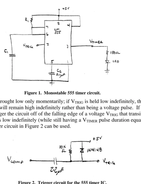
The basic monostable 555 timer circuit (see Figure 1) is used to produce an output voltage VTIMER that is a voltage pulse. The output voltage VTIMER is normally low (0V)
until the circuit is triggered; after triggering, the output voltage VTIMER transitions from
low (0V) to high (5V) for duration T = R1C1 (seconds) and then transitions back to 0V.
The input voltage VTRIG triggers the circuit; VTRIG is normally held high (5V) and is
brought low (0V) momentarily to trigger the circuit.
Figure 1. Monostable 555 timer circuit.
VTRIG must be brought low only momentarily; if VTRIG is held low indefinitely, the output
voltage VTIMER will remain high indefinitely rather than being a voltage pulse. If it is
desirable to trigger the circuit off of the falling edge of a voltage VTRIG that transitions
low and remains low indefinitely (while still having a VTIMER pulse duration equal to T =
A Trigger Circuit for the 555 Timer IC
The circuit in Figure 2 produces a momentary low trigger voltage VTRIG on the falling
edge of VCOMP. VCOMP is a voltage that is normally high (+5V) and is brought low (0V)
to trigger the 555 timer IC. (The input voltage is named VCOMP since it can be the output
voltage of a comparator circuit.) When VCOMP transitions from +5V to 0Vand remains at
0V, VTRIG falls to 0V and then exponentially rises to +5V. This means that VCOMP can be
brought low and held low, but VTRIG is only momentarily brought low and is suitable for
triggering the 555 timer IC. When VCOMP transitions from 0V to +5V, VTRIG rises to
approximately 5.6V and decays to 5V; the rising transition has no effect on triggering the 555 timer IC. The capacitor and resistor set the time constant of the transients that occur following edges of VCOMP.
Simulation of the Trigger Circuit
Figure 3 shows the schematic for an LTSPICE simulation of the trigger circuit. The source V2 produces the voltage VCOMP; the source is specified with a 1KΩ output
resistance using resistor RS (this would be the output resistance of the comparator producing VCOMP).
Figure 3. LTSPICE simulation of the trigger circuit.
Figure 4 shows the input voltage VCOMP. Figure 5 shows the output voltage VTRIG. When
the input voltage VCOMP falls from +5V to 0V, VTRIG falls to 0 and rises exponentially
with a time constant based on R1 and C1 (τ=R1C1). When the input voltage VCOMP rises
from 0V to +5V, VTRIG shows a voltage spike above +5V. The peak voltage of the spike
is limited by diode D1; when VTRIG rises above 5V, diode D1 shunts current and keeps
VTRIG from rising significantly above +5V. It has been shown in the lab that this positive
Figure 4. Input voltage VCOMP for the trigger circuit.
A Trigger Circuit for the 555 Timer IC
Testing the Trigger Circuit
Figure 6 shows a block diagram of the circuit used to test the trigger circuit. The infrared (IR) emitter is an IR light-emitting diode (LED) oriented toward the IR detector. The IR detector is an IR phototransistor oriented toward the IR emitter. The IR emitter and IR detector are separated by a distance of approximately one inch. When nothing obstructs the emitter from the detector, the output voltage of the detector VDET is approximately
+4V. The comparator compares VDET to a threshold voltage. When the detector voltage
falls below the threshold voltage, the output of the comparator VCOMP is approximately
0V (measured to be 0.174V). When the detector voltage rises above the threshold voltage, the output of the comparator VCOMP is +5V. The falling edge of the comparator
voltage VCOMP causes the trigger circuit to trigger the 555 timer as described earlier.
Figure 6. Diagram of test circuit used to test trigger.
Figure 7 shows the schematic of the IR emitter. The resistor was chosen so that
approximately 20 mA flow through the IR emitter diode. Figure 8 shows the schematic of the IR detector. The IR detector uses a phototransistor. In the test circuit, the
potentiometer connected to the phototransistor’s emitter was replaced with a fixed 1KΩ resistor. The output of the detector VDET is 0V when no light is incident upon the
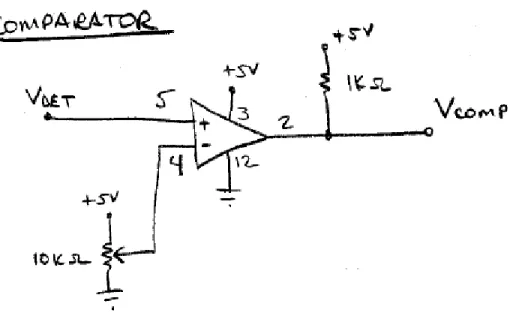
detector and +4V when the IR light from the emitter is unobstructed from the detector. The comparator schematic is shown in Figure 9. The potentiometer adjusts the threshold voltage of the comparator. For the test circuit, the threshold voltage was adjusted
between 2V and 4V. The output of the comparator is the input to the trigger circuit, and the trigger circuit triggers the 555 timer. The 555 circuit was constructed with R1 = 560 KΩ and C1 = 2.2 µF so that the pulse time period was 1.2 seconds. The output of the 555 timer IC was connected to an LED in series with a 180 Ω resistor to indicate the state of the 555 output.
Figure 7. Schematic of IR emitter.
A Trigger Circuit for the 555 Timer IC
Figure 9. Schematic of comparator.
Figure 10 shows a photo of the test circuit. The IR emitter is on the upper left of the breadboard; the IR detector is on the lower left of the board. The LED on right is normally off and turns on for 1.2 seconds when the light between the IR emitter and IR detector is obstructed. Even if an obstruction is placed between the IR emitter and detector for a long period of time, the LED lights for 1.2 seconds and then turns off.
Figure 10. Photograph of the test circuit.
This document is a circuit note for ECEN 3010 lab, University of Colorado at Boulder (William Newhall, 2008).