Fuzzy logic controller for DC motor position
control
Nurainaa Elias
Faculty of Manufacturing Engineering
University Malaysia Pahang
Pekan, Malaysia
[email protected]
Nafrizuan Mat Yahya
Faculty of Manufacturing Engineering
University Malaysia Pahang
Pekan, Malaysia
[email protected]
Abstract—This paper presents the position control of DC motor by using a fuzzy logic controller (FLC) with MATLAB
application. Firstly, the DC motor was modeled and converted to a subsystem in Simulink. Then the fuzzy logic controller is designed by using MATLAB toolbox. The scopes include the simulation and modeling of DC motor, fuzzy controller and different transfer function for DC motor model as a benchmark to the performance of the fuzzy system. The position control is an adaptation of assisted lifting device system. Fuzzy logic control can play an important role because knowledge-based design rules can be easily implemented in the system with unknown structure and it is going to be popular since the control design strategy is simple and practical. This makes FLC an alternative method used in a nonlinear industrial system. The results obtained from FLC are compared with different transfer function used for the dynamic response of the closed-loop system and also the system with and without a controller will be compared. Parameters such as peak position in degree, settling time in second and maximum overshoot in percent will be part of the simulation result. The overall performance shows that system with FLC performs better than compared to the system without FLC.
Keywords—fuzzy logic controller; DC motor; position control; MATLAB toolbox; Simulink
1.
I
NTRODUCTIONAn electric motor is an electric machine that converts electrical energy into mechanical energy. The electric motor can be powered by Direct Current (DC) sources such as batteries, motor vehicles or rectifiers, or by an Alternating Current (AC) sources, such as from power grid, inverters, or generators. DC motor has been selected in this project because it is widely used in industrial applications, robot manipulators and home appliances where speed and position control are required. The DC motors can come in many shapes and sizes, makes the development of dc motor application quite easy and flexible. It also has high reliabilities and low cost [1].
The scope of this project is to mimic the position control of assisted lifting device. With advances in computational capability, sensing and also control technology, assisted lifting device is introduced to eliminate these highly repetitive lifting of heavy awkward loads and unnatural motion [2]. Assisted lifting device such as hydraulic lift tables, pneumatic lift tables, and ball screw lift tables have been produced to reduce the risk of a repetitive stress injury [3]. A pneumatic lift table is powered by an air compressor to lift and position product for easy loading and unloading [4]. It typically uses some type of airbag either single, double, or multiple depending on the size and its application. Pneumatic lift tables are typically not used in heavy-duty applications with lower maximum capacities, where a large vertical lift is needed, or where accurate placement is required [4]. The ball screw scissor lift table uses an electric motor to turn a horizontal or vertical ball screw that actuates the scissors and platform up and down [5]. Hydraulic lift tables which are most widely available in the marketed are known to adjust the height of an object to enable a standing person for easily taking the object. The lifting table as shown in Fig. 1 includes upper and
lower platforms with a connecting scissors linkage mechanism providing straight upward and downward movement of the upper platform [6].
While such existing lifting table performs quite satisfactorily, a more ergonomic and intelligent alternative is frequently needed. It is because the existing hydraulic lift table still lifts slowly especially during loading process [7]. The hydraulic lift table also lifts slowly when a weightier load is placed on it. Some of the lift tables also did not lift the right adjusting height. So, due to the existing hydraulic lift table problems that lift the load slowly and not have accuracy position, this research is done to improve the existing hydraulic lift table with an introduction of DC motor with the fuzzy logic controller (FLC) that can enhance speed and also improve accuracy position, especially when loading the loads. By using the controller, the position can be control until it gets similar to the desired output that user needs. In control systems, fuzzy logic is considered as an alternative to conventional control theory in the control of complex nonlinear plants where precise mathematical modeling is difficult or impossible [8]. The main advantage of fuzzy logic as compared to conventional control approach resides in the fact that no mathematical modeling is required for the design of the controller. The control rules are based essentially on the knowledge of the system behavior and the experience of the control engineer. Since the fuzzy logic controller requires less complex mathematical operations than classical controllers, its implementation does not require very high-speed processors.
Therefore in this project, MATLAB/Simulink is used as a platform for designing the fuzzy logic controller. Simulation of a different model of DC motor also included in this project as a comparison in terms of its performance.
2.
M
ATERIAL ANDM
ETHODA. Fuzzy Logic Controller
A fuzzy logic controller (FLC) has four main components which are fuzzification interface, inference mechanism, rule base and defuzzification interface. The implementation of FLC required the choice of four key factors [9]. The number of fuzzy sets that constitute linguistic variables, mapping of the measurements onto the support sets, control protocol that determines the controller behavior and also the shape of membership functions. Thus, FLC can be tuned by adjusting controller parameters and also by changing control rules or membership functions.
Fuzzy logic controller (FLC) is one of the most popular control methods which is known for its multi-rule-based variable’s consideration. This method provides faster results compared to other Artificial Intelligent control methods such as Genetic Algorithm and Neural Networks. Being fast and robust are the main reasons for choosing FLC for controlling purpose in the current study. Compared to any other controller, FLC needs some inputs to generate some control signal. The inputs of FLC which are an error (e) and change of error (ce) are chosen based on the variances in position. Equations (1) and (2) show the chosen inputs for the FLC system.
𝑒 (𝑡) = 𝑤𝑟𝑒𝑓− 𝑤𝑚𝑒𝑎𝑠𝑢𝑟𝑒𝑑
𝑤𝑟𝑒𝑓
ce (t) = ∆ 𝑒(𝑡)∆𝑡 = e(t) – e (t − 1)
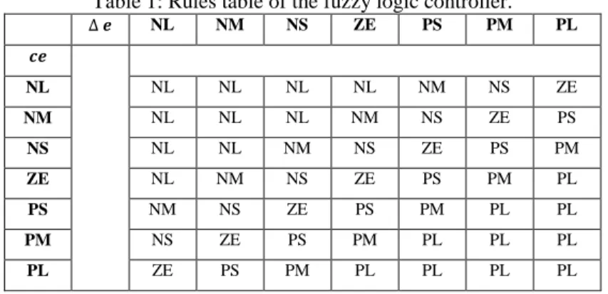
To implement the FLC in a problem, different steps of this algorithm must be taken which are as follows: Table 1: Rules table of the fuzzy logic controller.
∆ 𝒆 NL NM NS ZE PS PM PL 𝒄𝒆 NL NL NL NL NL NM NS ZE NM NL NL NL NM NS ZE PS NS NL NL NM NS ZE PS PM ZE NL NM NS ZE PS PM PL PS NM NS ZE PS PM PL PL PM NS ZE PS PM PL PL PL PL ZE PS PM PL PL PL PL
i. Fuzzification: The input defined in Equations (1) and (2) need to be fuzzified by some membership functions. For each input value, the respective membership function returns a value of μ. The max-min method was applied to extract from the triangle type membership function. Input and out variables of FLC consist of seven fuzzy sets namely NL (negative large), NM (negative medium), NS (negative small), ZE (zero), PS (positive small), PM (positive medium) and PL (positive large).
ii. Inference diagram: A rule base must be applied to the obtained membership function according to Mamdani. The rule table is designed and shown in Table 1. The 3D input-output surface is also obtained by using MATLAB FLC Inference.
B. DC Motor Model
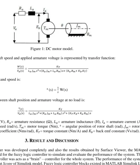
In recent years, DC motors are used in wide demand especially in drive system application due to a number of advantages such as preciseness, smooth operation, fast adaption, electrical efficiency and also high power density [10]. DC motors are most suitable for many adjustable position drives and also for use in the wide range of position control. A good position control system makes the DC motor appropriate for the applications in which adjustable position variation, for example in this project is assisted lifting devices that are commonly used in manufacturing industry. DC motor is designed using the Simulink block diagram. For this project, two different transfer function is used for representing the motor model. The main reasons for the difference are because of the model of DC motor and also the parameter that is used. In armature control of separately excited DC motors, the voltage applied to the armature of the motor is adjusted without changing the voltage applied to the field. Fig. 1 shows a separately excited DC motor equivalent model.
Figure 1: DC motor model.
The relation between rotor shaft speed and applied armature voltage is represented by transfer function:
𝑊(𝑠) 𝑉𝑎(s) =
𝐾𝑇
𝐿𝑎.𝐽𝑚.𝑠2+(𝑅𝑎.𝐽𝑚+ 𝐿𝑎.𝐵𝑚).s+ (𝑅𝑎.𝐵𝑚+ 𝐾𝑏.𝐾𝑇) (3)
The relation between position and speed is:
ᶿ (s) = 1𝑠 W(s) (4) Then the transfer function between shaft position and armature voltage at no load is:
ᶿ(𝑠) 𝑉𝑎(s) =
𝐾𝑇
𝐿𝑎.𝐽𝑚.𝑠3+(𝑅𝑎.𝐽𝑚+ 𝐿𝑎.𝐵𝑚).𝑠2+ (𝐾𝑇.𝐾𝑏+ 𝑅𝑎.𝐵𝑚).s (5)
Where 𝑣𝑎= armature voltage (V), 𝑅𝑎= armature resistance (Ω), 𝐿𝑎= armature inductance (H), 𝐼𝑎 = armature current (A), 𝐸𝑏= back emf (V), w = angular speed (rad/s), 𝑇𝑚= motor torque (Nm), ᶿ = angular position of rotor shaft (rad), 𝐽𝑚= rotor inertia (kg𝑚2), 𝐵𝑚= viscous friction coefficient (Nms/rad), 𝐾𝑇= torque constant (Nm/A) and 𝐾𝑏= back emf constant (Vs/rad).
3.
R
ESULT ANDD
ISCUSSIONAfter the fuzzy logic controller was developed completely and also the results obtained by Surface Viewer, the MATLAB Simulink model was developed for the fuzzy logic controller to simulate and evaluate the performance of the system. The rules that set in the fuzzy logic controller was acts as a “brain” – controller for the whole system. The performance of the system was simulated throughout the output Scope of Simulink model. Fuzzy logic controller blocks existed in MATLAB Simulink Library. The output actuator in the Simulink model used was the DC motor. The transfer function of DC motor was used inside the Simulink model to represent the output actuators.
The result from scope will be compared either by using the controller or without the controller for both transfer function. The first transfer function will be in 1-in 1 out subsystem while for the other transfer function will be 2-in 2-out subsystem will be used for DC motor position control.
A. 1-in 1-out Subsystem
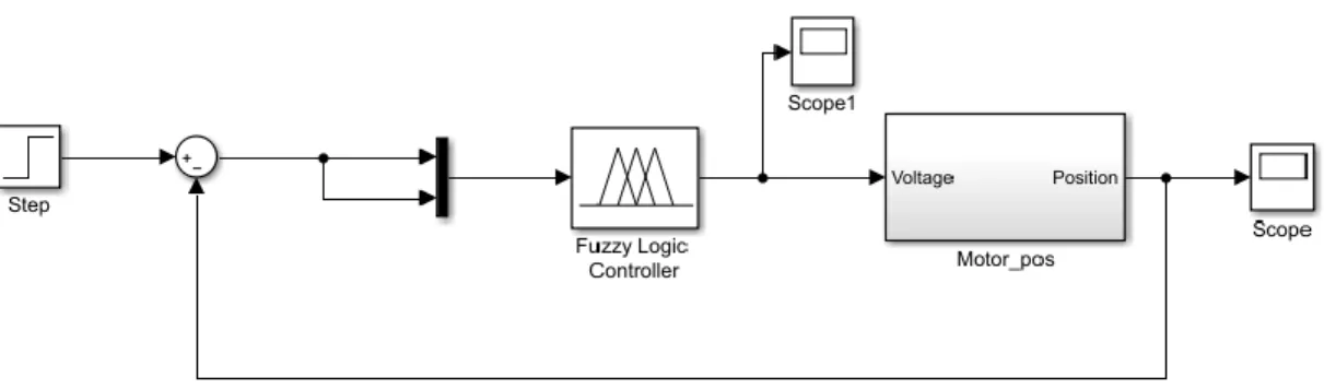
The performance of the system was evaluated by the simulation results from MATLAB Fuzzy Logic Toolbox and MATLAB Simulink. For the first block diagram, a 1-in 1-out subsystem is used for the DC motor block diagram. The system is named by Motor_pos as shown in Fig. 2. The input will be the voltage while the output is the position of the DC motor for the DC motor block diagram. The voltage will be converted to the output position by adding the value of inductance, resistance and also integrate the final value.
Figure 2: Block diagram for DC motor model for the 1-in 1-out subsystem.
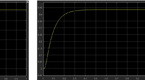
The Simulink model that is shown in Fig. 2 consists mainly of the fuzzy logic controller block and the DC motor block. The output of the DC motor block which is the motor position is monitored using a Scope to examine its response. The same Simulink model is used for transfer function without using the controller. The result from the scope is shown in Fig. 3.
Figure 3(a). Step response results for Simulink model with a fuzzy logic controller.
Figure 3(b). Step response results for Simulink model without a controller.
B. 2- in 2-out Subsystem
For the second block diagram, a 2-in 2-out subsystem is used for the DC motor block diagram. The system is named by DC Motor as shown in Fig. 4. The input ports will be the armature voltage (Va) and load torque (Tload) while the output ports are angular speed in (w) and position (teta).
The results for the step response for Simulink model that used 2-in 2-out subsystem is shown in Fig. 5.
Figure 5(a). Step response results for Simulink model with a fuzzy logic controller.
Figure 5(b). Step response results for Simulink model without a controller.
C. Comparative Results
The simulated results were interpreted as shown in Table 2. The values of the response parameters such as rise time, settling time and also percentage overshoot are tabulated.
Table 2: Simulation results comparison.
Metrics Values
Controller
1-in 1-out subsystem 2-in 2-out subsystem Without controller Fuzzy logic controller Without controller Fuzzy logic controller Rise Time (s) 0.05 0.06 0.13 0.11 Settling Time (s) 0.19 0.21 0.60 0.50 Overshoot (%) 0.08 0.20 0 0
From the simulation results, it shows that both subsystems that used fuzzy logic controller have the faster response than the system without a controller which was expected. However, the system without a controller works better than the system that used a controller in terms of having lower overshoot. Conclusively, controller reduced rise time, increased the overshoot and decreased the settling time by a small amount.
4.
C
ONCLUSION ANDF
UTURES
COPEThe objective of this project was successfully accomplished since fuzzy logic controller (FLC) is operated efficiency and delivered the result depend on the requirement of a user (fuzzy rules). The output actuators motor’s position with a fuzzy logic controller is achieved with good performance, stable and smooth as the desired set point compared to the system without using the fuzzy logic controller. Although the objectives of this present research had been successfully accomplished as discussed in the result, there are still have many improvements can be made to achieve better outcomes. Therefore, there are some recommendations for the future work to achieve the better outcomes and improve their further studies. Firstly, is to compare the results with other controllers such as PID controller although the fuzzy logic controller method in this project achieved the good performance. The comparison between both methods can make the better proven for the results and enhance the credibility of this study. Secondly, is to develop the experimental work or controller’s prototype in the real condition for assisted lifting device. This is because the limitation of this project is that not having the real data analysis for the DC motor position control for assisted lifting devices. Thus, I recommend the next researcher or future work can be made the combination between simulation and experimental result for fulfilling the experimental work in real condition to achieve the better result.
A
CKNOWLEDGMENTThis work was supported by University Malaysia Pahang. The authors would like to thank University Malaysia Pahang for encouraging this research.
R
EFERENCES[1] M. Namzov and O. Basturk, “DC motor position control using fuzzy proportional-derivative controllers with different defuzzification method,” Turkish Fuzzy System association, vol.1, pp. 36-54, 2010.
[2] J.M. Burnfield, Y. Shu, T. W. Buster, A. P. Taylor, M. M. McBride, and M. E. Krause, “Kinematic and electromyographic analyses of normal and device-assisted sit-to-stand transfers,” Gait and Posture, vol. 3, pp. 516–522, 2012.
[3] A. K. Gupta and S. K. Arora, World-class warehousing and material handling. Industrial automation and robotics. New Delhi: Laxmi Publication, 2009.
[4] P. J. Keir and C. W. MacDonell, “ Muscle activity during patient transfers: A preliminary study on the influence of lift assists and experience,” Ergonomics, vol. 3, pp. 296–306, 2004.
[5] W. Zhang, C. Zhang, J. Zhao, and C. Du, “A Study on the Static Stability of Scissor Lift,” The Open Mechanical Engineering Journal, vol. 9, pp. 954–960, 2015.
[6] S. Horino, “Environmental factors and work performance of foundry workers,” Journal of Human Ergology, vol. 6, pp. 159–166, 1977.
[7] K. L. Tan, Intelligent assist device. M.Sc. Thesis. Iowa State University, United States, 2001. [8] T. Williams, “Fuzzy Logic Simplifies Complex Control Problems,” Computer Design, March 1991.
[9] M. Mamdani, “Application of Fuzzy Logic to Approximate Reasoning Using Linguistic Synthesis,” IEEE Transactions on Computers, vol. C26, pp. 1182–1191, 1977.
[10] M. Islam, S. Mir, and T. Sebastian, “Issues in reducing the cogging torque of mass-produced permanent-magnet brushless dc motor,” Industry Application, IEEE Transaction on, vol. 40, pp. 813-820, May 2004.