Majority-Inverter Graph: A Novel Data-Structure and
Algorithms for Efficient Logic Optimization
Luca Amar´u, Pierre-Emmanuel Gaillardon, Giovanni De Micheli Integrated Systems Laboratory (LSI), EPFL, Switzerland. Abstract— In this paper, we presentMajority-Inverter Graph(MIG), a
novel logic representation structure for efficient optimization of Boolean functions. An MIG is a directed acyclic graph consisting of three-input majority nodes and regular/complemented edges. We show that MIGs include anyAND/OR/Inverter Graphs(AOIGs), containing also the well-known AIGs. In order to support the natural manipulation of MIGs, we introduce a new Boolean algebra, based exclusively on majority and inverter operations, with a complete axiomatic system. Theoretical results show that it is possible to explore the entire MIG representation space by using only five primitive transformation rules. Such feature opens up a great opportunity for logic optimization and synthesis. We showcase the MIG potential by proposing a delay-oriented optimization technique. Experimental results over MCNC benchmarks show that MIG optimization reduces the number of logic levels by 18%, on average, with respect to AIG optimization performed by ABC academic tool. Employed in a traditional optimization-mapping circuit synthesis flow, MIG optimization enables an average reduction of {22%, 14%, 11%} in the estimated{delay, area, power}metrics, before physical design, as compared to academic/commercial synthesis flows.
Categories and Subject Descriptors
B.6.3 [Design Aids]: Automatic Synthesis, Optimization General Terms
Algorithms, Design, Performance, Theory. Keywords
Majority Logic, Boolean Algebra, DAG, Logic Synthesis. I. INTRODUCTION
The performance of today’s digital integrated circuits largely depends on the capabilities of logic synthesis tools. In this context, efficient representation and optimization of Boolean functions are key features. Some data structures and algorithms have been proposed for these tasks [1]–[8]. Most of them consider, as basis operations, inversion (INV), conjunction (AND), disjunction (OR) [2]–[5] and if-then-else (MUX) [6], [7]. Other Boolean operations are derived by composition. Even though existing design automation tools, based on original optimization techniques [1]–[8], produce good results and handle large circuits, the possibility to push further the efficacy of logic synthesis continues to be of paramount interest to theElectronic Design Automation (EDA) community. With this aim in mind, we approach the logic optimization problem from a new angle.
In this paper, we propose a novel methodology to represent and op-timize logic, by using only majority (MAJ) and inversion (INV) as ba-sis operations. We present theMajority-Inverter Graph(MIG), a logic representation structure consisting of three-input majority nodes and regular/complemented edges. MIGs include any AND/OR/Inverter Graphs (AOIGs), therefore containing also AIGs [8]. To provide native manipulation of MIGs, we introduce a novel Boolean algebra, based exclusively on majority and inverter operations. A set of five primitive transformations forms a complete axiomatic system. Using
Permission to make digital or hard copies of all or part of this work for personal or classroom use is granted without fee provided that copies are not made or distributed for profit or commercial advantage and that copies bear this notice and the full citation on the first page. Copyrights for components of this work owned by others than ACM must be honored. Abstracting with credit is permitted. To copy otherwise, or republish, to post on servers or to redistribute to lists, requires prior specific permission and/or a fee. Request permissions from [email protected].
DAC ’14, June 1-5 2014, San Francisco, CA, USA Copyright 2014 ACM 978-1-4503-2730-5/14/06$15.00. http://dx.doi.org/10.1145/2593069.2593158
a sequence of such primitive axioms, it is possible to explore the entire MIG representation space. This remarkable property opens up great opportunities in logic optimization and synthesis. We showcase the potential of MIGs by proposing a delay-oriented optimization technique. Experimental results, over the MCNC benchmark suite, show that MIG optimization decreases the number of logic levels by 18%, on average, with respect to AIG optimization run by ABC academic tool. Applied in a standard optimization-mapping circuit synthesis flow, MIG optimization enables a reduction in the estimated {delay, area, power} metrics of {22%, 14%, 11%}, on average before physical design, as compared to academic/commercial synthesis flows.
The study of majority-inverter logic synthesis is also motivated by the design of circuits in emerging technologies. In the quest for increasing computational performance per unit area [9], major-ity/minority gates are natively implemented in different nanotech-nologies [10]–[12] and also extend the functionality of traditional NAND/NOR gates. In this scenario, MIGs and their algebra represent the natural methodology to synthesize majority logic circuits in emerging technologies. In this paper, we focus on standard CMOS, to first showcase the interest of MIGs in an ordinary design flow.
The remainder of this paper is organized as follows. Section II pro-vides a background on logic representation and optimization. Section III presents MIGs and their new associated Boolean algebra. Section IV describes the optimization of MIGs using primitive transformation rules. Section V validates, through experimental results, MIG-based optimization and also presents and compares synthesis results to state-of-art academic/commercial tools. Section VI concludes the paper.
II. BACKGROUND ANDMOTIVATION
This section presents relevant background on logic representations and optimization for logic synthesis. Notations and definitions for Boolean algebra and logic networks are also introduced.
A. Logic Representation and Optimization
Virtually, all digital integrated circuits are synthesized thanks to efficient logic representation forms and associated optimization algorithms [1]. Early data structures and related optimization algo-rithms [2] are based on two-level representation of Boolean functions in Sum Of Product (SOP) form, which is a disjunction (OR) of conjuctions (AND) where variables can be complemented (INV). Another pioneering data structure is the Binary Decision Diagram (BDD) [6]: a canonical representation form based on nested if-then-else (MUX) formulas. Later on, multi-level logic networks [3], [4] emerged, employing AND, OR, INV, MUX operations as basis functions, with more scalable optimization and synthesis tools [4], [7]. To deal with the continuous increase in logic designs complexity, a step further is enabled by [5], where multi-level logic networks are made homogenous, i.e., consisting of only AND nodes interconnected by regular/complement (INV) edges. The tool ABC [8], which is based on theAND-Inverter Graphs(AIGs), is considered the state-of-art academic software for (large) optimization and synthesis.
We propose, in this paper, a new logic optimization paradigm that aims at extending the capabilities of modern synthesis tools.
B. Notations and Definitions
1) Boolean Algebra: In the binary Boolean domain, the symbol B indicates the set of binary values {0,1}, the symbols ∧ and ∨ represent the conjunction (AND) and disjunction (OR) operators, the symbol ′
represents the complementation (INV) operator and 0/1 are the false/true logic values. A standard Boolean algebra is a non-empty set(B,∧,∨,′
,0,1)subject tocommutativity, associativity, distributivity, identity and complement axioms over∧,∨and′
[16]. Boolean algebra is the ground to operate on logic networks.
2) Logic Network: A logic network is aDirected Acyclic Graph (DAG) with nodes corresponding to logic functions and directed edges interconnecting the nodes. The direction of the edges follow the natural computation from inputs to outputs. The terms logic network, Boolean network, and logic circuit are used interchangeably in this paper. The incoming edges of a node link either to other nodes, to input variables or to logic constants 0/1. Two logic networks are said equivalentwhen they represent the same Boolean function. A logic network is saidirredundantif no node can be removed without altering the represented Boolean function. A logic network is said homogeneous if each node has an indegree (number of incoming edges, fan-in) equal to k and represents the same logic function. In a homogeneous logic network, edges can have a regular or complemented attribute, to support local complementation. The depth of a node is the length of the longest path from any input variable to the node. The depth of a logic network is the largest depth of a node. The size of a logic network is its number of nodes.
3) Majority Function: Then-input (n odd) majority functionM
returns the logic value assumed by more than half of the inputs. III. MAJORITY-INVERTERGRAPH
In this section, we present MIGs and their associated Boolean algebra. Notable properties of MIGs are discussed.
A. MIG Logic Representation
Definition An MIG is a homogeneous logic network with indegree equal to 3 and with each node representing the majority function. In an MIG, edges are marked by a regular or complemented attribute.
We show the properties of MIGs by comparison to the general AND/OR/Inverter Graphs (AOIGs), that are also including the pop-ular AIGs [8]. For this purpose, note that the majority operator
M(a, b, c) behaves as the conjunction operator AN D(a, b) when
c = 0 and as the disjunction operator OR(a, b) when c = 1. Therefore, majority can be seen as a generalization of conjunction and disjunction. This property leads to the following theorem.
Theorem 3.1: MIGs⊃AOIGs.
Proof: In both AOIGs and MIGs, inverter are represented by complemented edge markers. An AOIG node can be seen as a special case of an MIG node, with the third input biased to logic 0 or 1 to realize an AND or OR, respectively. On the other hand, an MIG node is not a special case of an AOIG node, as the functionality of the three input majority cannot be realized by a single AND or OR.
Fig. 1 depicts two logic representation examples for MIGs. They are obtained by translating their optimal AOIG representations into MIGs. Note that even if such logic networks are optimal for AOIGs, they can be further optimized with MIGs, as detailed later.
As a corollary of Theorem 3.1, MIGs include also AIGs and are capable to represent any logic function (universal representation). This is formalized in the following.
Corollary 3.2: MIGs⊃AIGs.
Proof:MIGs⊃AOIGs⊃AIGs =⇒ MIGs⊃AIGs Corollary 3.3: MIG is an universal representation form.
a)
b)
AOIG MIG AOIG MIG
f=x⊕y⊕z x z z y y OR AND AND OR AND AND y v u x OR AND AND g=x(y+uv) y 1 v 1 u 1 x g=x(y+uv) MAJ MAJ MAJ f=x⊕y⊕z 1 x z z y y 1 1 1 1 1 MAJ MAJ MAJ MAJ MAJ MAJ
Fig. 1. Examples of MIG representations (right) for (a)f=x⊕y⊕zand (b)g=x(y+uv)derived by transposing their optimal AOIG representations (left). Complement attributes are represented by bubbles on the edges.
Proof:MIGs⊃AIGs that is an universal representation [5]. So far, we have shown that MIGs can be configured to behave as AOIGs. Hence, in principle, they can be manipulated using traditional AND/OR techniques. However, the potential of MIGs goes beyond standard AOIGs and, in order to unlock their full expressive power, we introduce a new Boolean algebra, natively supporting the majority/inverter functionality.
B. MIG Boolean Algebra
We propose here a novel Boolean algebra1, defined over the set
(B, M,′
,0,1), where M is the majority operator of three variables and ′
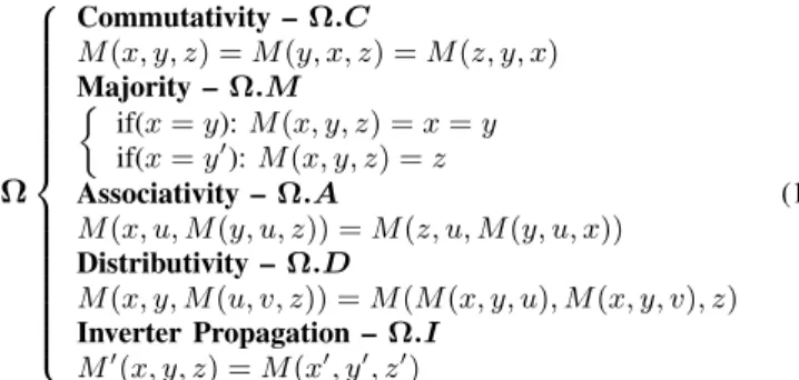
is the complementation operator. The following set of five primitive transformation rules, referred to asΩ, is anaxiomatic system for(B, M,′
,0,1). All the variables considered hereafter belong toB.
Ω Commutativity –Ω.C M(x, y, z) =M(y, x, z) =M(z, y, x) Majority – Ω.M if(x=y):M(x, y, z) =x=y if(x=y′ ):M(x, y, z) =z Associativity –Ω.A M(x, u, M(y, u, z)) =M(z, u, M(y, u, x)) Distributivity –Ω.D M(x, y, M(u, v, z)) =M(M(x, y, u), M(x, y, v), z) Inverter Propagation –Ω.I M′ (x, y, z) =M(x′ , y′ , z′ ) (1) We prove that(B, M,′
,0,1)axiomatized byΩis a Boolean algebra by showing that it induces a complemented distributive lattice [17].
Theorem 3.4: The set (B, M,′
,0,1) subject to axioms inΩis a Boolean algebra.
Proof: The systemΩ embed median algebra axioms [13]. In such scheme, M(0, x,1) = x follows by Ω.M. In [18], it is proved that a median algebra with elements 0 and 1 satisfying
M(0, x,1) = xis a distributive lattice. Moreover, in our scenario, complementation is well defined and propagates through the operator
M (Ω.I). Thus, a complemented distributive lattice arises. Every complemented distributive lattice is a Boolean algebra [17].
Note that there are other possible axiomatic systems. For example, it is possible to show that in the presence ofΩ.C,Ω.AandΩ.M, the rule inΩ.Dis redundant [14]. In this work, we considerΩ.Das part of the axiomatic system for the sake of simplicity. Desirable proper-ties for a logic system are soundness and completeness. Soundness ensures that if a formula is derivable from the system, then it is valid. Completeness guarantees that each valid formula is derivable from the system. We prove that the proposed Boolean algebra is sound and complete by linking back to Stone’s theorem [19].
Theorem 3.5: The Boolean algebra(B, M,′
,0,1)axiomatized by
Ωis sound and complete.
Sketch of The Proof: Owing to Stone’s representation theorem, every Boolean algebra is isomorphic to a field of sets [19]. Stone’s theorem implies soundness and completeness in the original logic system [20]. Since the proposed system is a Boolean algebra, Stone’s duality applies and soundness and completeness are true.
Intuitively, every (M,′
,0,1)-formula can be interpreted as an MIG. Thus, the Boolean algebra induced byΩis naturally applicable in MIG manipulation2. We show hereafter that any two equivalent MIGs can be transformed one into the other byΩ.
Theorem 3.6: It is possible to transform any MIGαinto any other logically equivalent MIGβ, by a sequence of transformations inΩ.
Proof: Say thatα is one-to-one equivalent to the(M,′
,0,1) -formula A andβis one-to-one equivalent to the(M,′
,0,1)-formula B. All tautologies in (B, M,′
,0,1) are theorems provable by Ω
[Theorem 3.5]. The statementA=B is equivalent to the tautology
M(1, M(A′
, B′
,0), M(A, B,0)) = 1(that meansA⊕B = 1). Us-ing the sequence inΩprovingM(1, M(A′
, B′
,0), M(A, B,0)) = 1
we can then transform MIGαinto MIGβ.
As a consequence of Theorem 3.6, it is possible to traverse the entire MIG representation space just by using Ω. From a logic optimization perspective, it means that we can always reach a desired MIG starting from any other equivalent MIG. However, the lenght of the exact transformation sequence might be impractical for modern computers. To alleviate this problem, we derive from
Ω three powerful transformations, referred to as Ψ, that facilitate the MIG manipulation task. The first, relevance (Ψ.R), replaces and simplifies reconvergent variables. The second, complementary associativity(Ψ.C), deals with variables appearing in both polarities. The third and last, substitution(Ψ.S), extends variable replacement also in the non-reconvergent case. We represent a general variable replacement operation, say replacexwithyin all its appearence in
z, with the symbol zx/y.
Ψ Relevance –Ψ.R M(x, y, z) =M(x, y, zx/y′) Complementary Associativity –Ψ.C M(x, u, M(y, u′ , z)) =M(x, u, M(y, x, z)) Substitution –Ψ.S M(x, y, z) = M(v, M(v′ , Mv/u(x, y, z), u), M(v ′ , Mv/u′(x, y, z), u ′ )) (2) By showing thatΨcan be derived fromΩ, the validity ofΨfollows fromΩsoundness.
Theorem 3.7: The transformations inΨfollow fromΩ.
Proof: Relevance (Ψ.R): Let S be the set of all the possible primary input combinations forM(x, y, z). LetSx=y(Sx=y′) be the subset ofS such thatx=y(x=y′
). Note thatSx=y∩Sx=y′=∅ andSx=y∪Sx=y′=S. According toΩ.M, variablezinM(x, y, z) is only relevant for Sx=y′. Thus, it is possible to replacexwithy
′
(x/y′
) in all its appearance inz, preserving the original functionality. Complementary Associativity (Ψ.C): M(x, u, M(u′ , v, z)) =M(M(x, u, u′ ), M(x, u, v), z) (Ω.D) M(M(x, u, u′ ), M(x, u, v), z) =M(x, z, M(x, u, v))(Ω.M) Substitution (Ψ.S): We setM(x, y, z) =kfor brevity.
k=M(v, v′ , k) =(Ω.M) =M(M(u, u′ , v), v′ , k) =(Ω.M) =M(M(v′ , k, u), M(v′ , k, u′ ), v) =(Ω.D) Then,M(v′ , k, u) =M(v′ , kv/u, u)(Ψ.R) and M(v′ , k, u′ ) =M(v′ , kv/u′, u)(Ψ.R)
2Transformations involving MIG inner nodes with multiple outputs require
temporarily nodes duplication. Sharing is re-enabled immediately upon.
Recalling that k = M(x, y, z), we finally obtain: M(x, y, z) =
M(v, M(v′ , Mv/u(x, y, z), u), M(v ′ , Mv/u′(x, y, z), u ′ ))
So far, we have presented the theory for MIGs and their native Boolean algebra. We show now how to optimize an MIG accordingly.
IV. MIG OPTIMIZATION
The optimization of an MIG, representing a Boolean function, ultimately consists of its transformation into a different MIG, with better figures of merit in terms of area (size), delay (depth), and power (switching activity). In the rest of this section, we present heuristic algorithms to optimize the size, depth and activity of an MIG using transformations fromΩandΨ.
A. Optimizing the Size of an MIG
To optimize the size of an MIG, we aim at reducing its number of nodes. Node reduction can be done, at first instance, by applying the majority rule. In the novel Boolean algebra domain, that is the ground to operate on MIGs, this corresponds to the evaluation of the majority axiom (Ω.M) from Left to Right (L → R), as
M(x, x, z) = x. A different node elimination opportunity arises from the distributivity axiom (Ω.D), evaluated from Right to Left (R→L), asM(x, y, M(u, v, z)) =M(M(x, y, u), M(x, y, v), z). By applying repeatedlyΩ.ML→RandΩ.DR→Lover an entire MIG, we can actually eliminate nodes and thus reduce its size. Note that the applicability of majority and distributivity depends on the peculiar MIG structure. Indeed, there may be MIGs where no direct node elimination is evident. This is because (i) the optimal size is reached or (ii) we are stuck in a local minima. In the latter case, we want to reshape the MIG in order to enforce new reduction opportunities. The rationale driving the reshaping process is to locally increase the number of common inputs/variables to MIG nodes. For this purpose, the associativity axioms (Ω.A, Ψ.C) allow us to move variables between adjacent levels and the relevance axiom (Ψ.R) to exchange reconvergent variables. When a more radical transformation is beneficial, the substitution axiom (Ψ.S) replaces pairs of independent variables, temporarily inflating the MIG. Once the reshaping process created new reduction opportunities, majority (Ω.ML→R) and distributivity (Ω.DR→L) run again over the MIG
simplifying it. Reshape and elimination processes can be iterated over a user-defined number of cycles, calledeffort. Such MIG-size optimization strategy is summarized in Alg. 1.
Algorithm 1MIG-size Optimization Pseudocode
INPUT:MIGα OUTPUT:Optimized MIGα.
for(cycles=0; cycles<effort; cycles++)do
Ω.ML→R(α); Ω.DR→L(α); Ω.A(α); Ψ.C(α); Ψ.R(α); Ψ.S(α); Ω.ML→R(α); Ω.DR→L(α); end for reshape eliminate
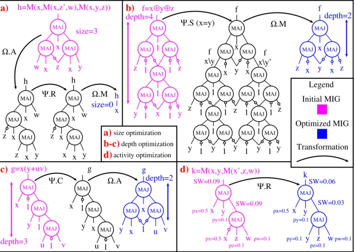
For the sake of clarity, we comment on the MIG-size optimization procedure of a simple example, reported in Fig. 2(a). The input MIG is equivalent to the formula M(x, M(x, z′
, w), M(x, y, z)), which has no evident simplification by majority and distributivity axioms. Consequently, the reshape process is invoked to locally increase the number of common inputs. AssociativityΩ.AswapwandM(x, y, z)
in the original formula obtaining M(x, M(x, z′
, M(x, y, z)), w), where variablesxand z are close to the eachother. Later, relevance
Ψ.Rapplies to the inner formulaM(x, z′
, M(x, y, z)), exchanging variable z with x and obtaining M(x, M(x, z′
, M(x, y, x)), w). At this point, the final elimination process runs, simplifying the reshaped representation as M(x, M(x, z′
, M(x, y, x)), w) =
M(x, M(x, z′
, x), w) =M(x, x, w) =xby usingΩ.ML→R. The
depth=3
depth=4
depth=2
Ω
.M
z w
y
x
1
Ω
.A
y
1
v
u
1
x
g=x(y+uv)
Ψ.
C
g
MAJ MAJ MAJy
1
v
1
u
x
x
MAJ MAJ MAJg
v
y
x
1
u
x
MAJ MAJ MAJx
w
h=M(x,M(x,z’,w),M(x,y,z))
y
w
x
z
x
x
MAJ MAJ MAJy
x
x
z
x
MAJ MAJ MAJz
w
y
x
x
z
x
MAJ MAJ MAJx
h
h
h
Ω
.M
Ω
.A
Ψ.
R
f
x\y’
y
x
x
Ψ.
S (x=y)
z
z
y
y
1
x
1
b)
f=x
⊕
y
⊕
z
1
1
1
1
f
x
x\y
y
z
z
y
y
1
1
1
1
1
1
f
MAJ MAJ MAJ MAJ MAJ MAJ MAJ MAJ MAJ MAJ MAJ MAJ MAJ MAJ MAJy
z
y
1
1
1
1
1
1
MAJ MAJ MAJ MAJ MAJ MAJf
z
z
x
y
x
x
MAJ MAJ MAJx
k=M(x,y,M(x’,z,w))
MAJ MAJ SW=0.09 SW=0.09 py=0.1z w
y
y
x
MAJ MAJ SW=0.06 SW=0.03k
Ψ.
R
px=0.5 px=0.5 pz=0.1 pw=0.1 py=0.1 px=0.5 py=0.1 pz=0.1 pw=0.1a)
c)
d)
size=3
size=0
depth=2
Legend
Initial MIG
Optimized MIG
Transformation
size optimizationa)
depth optimizationb-c)
activity optimizationd)
Fig. 2. Examples of MIG optimization for (a) size, (b-c) depth and (c) switching activity. The initial MIGs appear in purple and the final MIGs are in blue.
Note that MIGs resulting from Alg. 1 areirredundant, thanks to the final eliminationstep. Portions of Alg. 1 can be interlaced with other optimization methods, to achieve a size-recovery phase. B. Optimizing the Depth of an MIG
To optimize the depth of an MIG, we aim at reducing the length of its critical path. A valid strategy for this purpose is to move late arrival (critical) variables close to the outputs. In order to explain how critical variables can be moved preserving the original functionality, we consider the general case in which a part of the critical path appears in the form M(x, y, M(u, v, z)). If the critical variable is
x, or y, no simple move reduce the depth of M(x, y, M(u, v, z)). Whereas, instead, the critical variable belongs to M(u, v, z), sayz, depth reduction is achievable. We focus on the latter case, with order
tz > tu≥tv> tx≥tyfor the variables arrival time (depth). Such order arises from (i) an unbalanced MIG whose inputs have equal arrival times or (ii) a balanced MIG whose inputs have different arrival times. In both cases, z is the critical variable arriving later than u, v, x, y, hence the local depth is tz + 2. If we apply the distributivity axiom Ω.D from left to right (L → R), we obtain
M(x, y, M(u, v, z)) = M(M(x, y, u), M(x, y, v), z) where z is pushed one level up, reducing the local depth totz+1. Such technique is applicable to a broad range of cases, as all the variables appearing in M(x, y, M(u, v, z)) are distinct and independent. However, a size penalty of one node is introduced. In the favorable cases for which associativity axioms (Ω.A,Ψ.C) apply, critical variables can be pushed up with no penalty. Furthermore, where majority axiom applies Ω.ML→R, it is possible to reduce both depth and size. As
noted earlier, there exist cases for which moving critical variables
cannot improve the overall depth. This is because (i) the optimal depth is reached or (ii) we are stuck in a local minima. To move away from a local minima, thereshape process is useful. Reshape and critical variable push-up processes can be iterated over a user-defined number of cycles, calledeffort. Such MIG-depth optimization strategy is summarized in Alg. 2.
Algorithm 2MIG-depth Optimization Pseudocode
INPUT:MIGα OUTPUT:Optimized MIGα.
for(cycles=0; cycles<effort; cycles++)do
Ω.ML→R(α); Ω.DL→R(α); Ω.A(α); Ψ.C(α); Ω.A(α); Ψ.C(α); Ψ.R(α); Ψ.S(α); Ω.ML→R(α); Ω.DL→R(α); Ω.A(α); Ψ.C(α); end for reshape push-up
We comment on the MIG-depth optimization procedure using two examples depicted by Fig. 2(b-c). The considered functions aref=
x⊕y⊕z and f = x(y+uv) with initial MIG representations translated from their optimal AOIGs. In both of them, all inputs have 0 arrival time, thus no direct push-up operation is advantageous. The reshape process is invoked to move away from local minima. Forf=
x(y+uv), complementary associativityΨ.C enforces variablexto appear in two adjacent levels, while forf=x⊕y⊕zsubstitutionΨ.S
replacesxwithy, temporarily inflating the MIG. After this reshaping, the push-up procedure is applicable. Forf=x(y+uv), associativity
Ω.A exchanges 1′
with M(u,1′
, v) in the top node, reducing by one level the MIG depth. For f =x⊕y⊕z, majorityΩ.ML→R heavily simplifies the structure and reduces by two levels the original
MIG depth. The optimized MIGs are much shorter than their optimal AOIGs counterparts. Note that the depth of MIGs resulting from Alg. 2 cannot be reduced by any direct push-up operation.
C. Optimizing the Activity of an MIG
To optimize the overall switching activity of an MIG, we aim at reducing (i) its size and (ii) the probability for nodes to switch from logic0to1, or viceversa. For the size reduction task, we can run the MIG-size optimization algorithm described previously. To minimize the switching probability, we want that nodes do not change values often, i.e., the probability of a node to be logic 1 (p1) is close to
0 or 1. For this purpose, relevance Ψ.R and substitution Ψ.S can exchange variables with not desirablep1∼0.5with more favorable variables having p1 ∼ 1 or p1 ∼ 0. Fig. 2(d) shows an example where relevanceΨ.Rreplaces a variablexhaving p1= 0.5with a reconvergent variabley having p1 = 0.1, thus reducing the overall MIG switching activity.
V. EXPERIMENTALRESULTS
In this section, we show the advantage of MIG optimization and synthesis as compared to state-of-art academic/commercial tools. A. MIG Optimization
We present here the experimental method and results for logic optimization based on the MIG theory.
1) Methodology: We developed MIGhty a logic manipulation package for MIGs, consisting of about 6k lines of C code. Different optimization methods are implemented inMIGhty. In this paper, we employ depth-optimization interlaced with size and activity recovery phases. The MIGhtypackage reads a Verilog description of a com-binational logic circuit, flattened into Boolean primitives, and writes back a Verilog description of the optimized MIG. The benchmarks are the largest circuits from the MCNC suite, ranging from 0.1k and 15k nodes. For the sake of illustration, we considered separately a large logic compression circuit having (unoptimized) 0.3M nodes. We compare MIGs with AIGs optimized by ABC tool [8] and BDDs decomposed by BDS tool [7]. The resyn2 script is used for ABC, while the default execution options are used for BDS.
MIG AIG BDD 2,300 2,400 2,500 2,600 2,700 650 700 30 35 40 Size Activity Depth
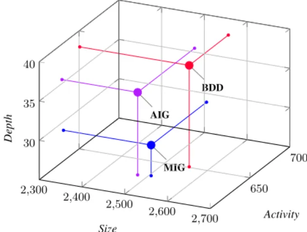
Fig. 3. Optimization space for logic circuits optimized with MIG (blue), AIG (violet) and decomposed BDD (red).
2) Results: Table I-top summarizes experimental results for logic optimization. The average depth of MIGs is 18.6% smaller than AIGs and 23.7% smaller than decomposed BDDs. The average size of MIGs is roughly the same than AIGs, just 0.9% of difference, but 2.1% smaller than decomposed BDDs. The average activity of MIGs is again the same as AIGs, just 0.3% of difference, but 3.1% smaller than decomposed BDDs. Fig. 3 depicts these results in a
3D (size,depth,activity) space. Using a size·depth·activity figure of merit, MIGs are 17.5% better than AIGs and 27.7% better than decomposed BDDs. The runtime for MIGs is slightly longer than ABC tool [8] (+7.1%) but 68% shorter than BDS [7]. Regarding the large compression benchmark, ABC produces an optimized AIGs with 167k nodes and 31 levels in 11.3 seconds. With MIGs instead, the circuit is optimized with 170k (+1.7% w.r.t. ABC) nodes and 28 levels (-9.6% w.r.t. ABC) in 21.5s. Results for the large compression circuit andclmabenchmark are not given for decomposed BDDs due to some glitches during BDS software execution.
B. MIG-based Synthesis
Experimental methods and results for MIG-based logic synthesis are presented hereafter.
1) Methodology: We employMIGhtyin a traditional optimization-mappingsynthesis flow and we compare its results to state-of-art aca-demic and commercial tools. For this purpose, a standard cell library consisting of MIN-3, MAJ-3, XOR-2, XNOR-2, NAND-2, NOR-2 and INV logic gates is characterized for CMOS 22nm technology [15]. Technology mapping after MIG-optimization is carried out using a proprietary mapping tool. The academic counterpart is ABC [8] (AIGs optimization) followed by the same proprietary technology mapping tool as for MIGs. Physical design is not taken into account in any synthesis flow. Hence,{delay, area, power}metrics are estimated from the synthesized gate-level netlist.
MIG AIG CST 260 280 300 320 340 600 650 700 750 1.2 1.4 1.6 Area(µm2) Power(µW) Delay ( ns )
Fig. 4. Synthesis space for logic circuits optimized with MIG (blue), AIG (violet) and Commercial Synthesis Tool (CST) (brown).
2) Results: Table I-bottom summarizes experimental results for MIG-based logic synthesis and its counterpart flows. On average, the MIG flow generates{delay, area, power}estimated metrics that are {22%, 14%, 11%}smaller than the best academic/commercial counterpart. Fig. 4 shows the dominance of MIGs synthesis results over AIGs and commercial synthesis tool, in a 3D (area,delay,power) space. While, in logic optimization, MIGs were mainly shorter than AIGs, in logic synthesis they enable also remarkable area and power savings. The reason for such improvement is twofold. On the one hand, the structure of MIGs is further simplifiable by technology mapping algorithms based on Boolean techniques, such as equiva-lence checking using BDDs, internal flexibilities computation (don’t cares), and others. This is especially effective when MIG nodes are partially fed by logic 1/0. One the other hand, the presence of MAJ-3 and MIN-3 gates in the standard-cell library allows us to natively recognize and preserve MIG nodes, when their decomposition in simpler functions is not advantageous.
C. Discussions
Experimental results validate the potential of MIGs in logic optimization and synthesis. Even though the proposed algorithms
TABLE I
LOGICOPTIMIZATION ANDSYNTHESISRESULTS
Logic Optimization MIG AIG BDD Decomposition
Benchmarks I/O Size Depth Activity Time Size Depth Activity Time Size Depth Activity Time
C1355 41/32 481 18 133.60 0.1 392 18 126.36 0.1 315 19 109.33 0.2 C1908 33/25 459 23 124.98 0.1 363 25 159.08 0.1 414 31 169.68 0.4 C6288 32/32 2237 86 784.62 0.2 2045 94 797.91 0.3 2187 98 883.12 0.3 bigkey 487/421 4299 9 789.02 0.7 4834 9 846.57 0.5 4563 14 822.76 3.2 my adder 33/17 265 19 58.15 0.1 137 33 49.86 0.1 211 37 64.83 0.3 cla 129/65 1028 24 363.57 0.2 902 38 329.17 0.1 918 39 317.44 0.2 dalu 75/16 1443 21 283.12 0.1 1116 30 264.92 0.1 1626 39 303.70 1.6 b9 41/21 97 6 16.95 0.1 84 7 16.65 0.1 96 9 17.20 0.1 count 35/16 176 7 32.77 0.1 127 19 18.87 0.1 134 17 19.05 0.1 alu4 14/8 1380 14 237.38 0.1 1421 14 249.52 0.1 1773 27 349.33 0.5
clma 416/115 12449 42 3626.38 1.2 12928 46 3712.38 1.1 N.A. N.A. N.A. N.A.
mm30a 124/120 1174 101 209.52 0.3 1004 125 164.49 0.2 1187 111 155.29 0.9
s38417 1494/1571 8260 22 1932.78 0.8 8053 25 1854.26 1.0 8210 28 1989.22 4.1
misex3 14/14 1323 13 233.09 0.2 1274 14 209.27 0.1 1223 16 198.71 0.4
Average 212/176 2505.1 28.9 630.42 0.30 2477.1 35.5 628.52 0.28 2556.1 37.9 650.86 0.95
Logic Synthesis MIG + Tech. Map. AIG + Tech. Map. Commercial Synthesis Tool
Benchmarks I/O A (µm2) D (ns) P (µW) A (µm2) D (ns) P (µW) A (µm2) D (ns) P (µW) C1355 41/32 56.34 0.74 226.68 56.27 0.76 203.55 56.34 0.76 205.54 C1908 33/25 44.72 0.78 132.98 53.47 1.06 155.07 53.54 0.99 155.96 C6288 32/32 361.47 3.18 1604.30 354.54 3.44 1822.21 343.41 3.44 1742.20 bigkey 487/421 388.57 0.82 722.68 541.24 0.73 981.06 538.09 0.70 1010.32 my adder 33/17 22.68 1.19 36.17 23.23 1.68 41.10 23.31 1.68 41.21 cla 129/65 149.52 1.42 398.34 139.92 2.32 355.47 139.50 2.33 356.53 dalu 75/16 116.34 1.07 179.42 103.25 0.94 145.10 109.97 1.09 147.98 b9 41/21 12.88 0.22 19.75 13.72 0.22 20.67 14.49 0.26 23.06 count 35/16 20.16 0.91 28.04 18.76 1.07 24.87 18.76 1.07 24.87 alu4 14/8 150.15 0.65 225.16 254.80 0.67 386.71 229.25 0.69 343.62 clma 416/115 888.79 1.59 1806.65 1180.83 1.69 2191.77 1315.02 1.62 2588.09 mm30a 124/120 130.41 2.12 210.95 148.12 4.71 240.28 164.56 3.35 296.29 s38417 1494/1571 1287.44 1.20 2577.00 1268.05 1.34 2559.54 1307.59 1.43 2589.28 misex3 14/14 159.88 0.66 234.09 291.48 0.92 379.62 207.48 0.73 284.62 Average 212/176 270.67 1.18 600.16 317.71 1.53 679.07 322.95 1.43 700.68
are simple as compared to elaborated state-of-art techniques, they produce already competitive results, thanks to the expressive power of MIGs and their associated algebra. Indeed, there exist logic circuits, for example the ones in Fig 1 and Fig. 2(b-c), for which traditional optimization reaches its limits while the proposed methodology can optimize further. In particular, MIGs open the opportunity for efficient synthesis of datapath circuits, where majority logic is dominant.
VI. CONCLUSIONS
We presented, in this paper, Majority-Inverter Graph (MIG), a novel logic representation structure for efficient optimization of Boolean functions. To natively optimize MIGs, we proposed a new Boolean algebra, based solely on majority and inverter operations, with a complete axiomatic system. Experimental results, over the MCNC benchmark suite, show that delay-oriented MIG optimization reduces the number of logic levels by 18%, on average, with respect to AIG optimization run by ABC academic tool. Employed in a stan-dardoptimization-mappingcircuit synthesis flow, MIG optimization enables a reduction in the estimated{delay, area, power}metrics of {22%, 14%, 11%}, on average before physical design, as compared to academic/commercial counterparts. MIGs extend the capabilities of modern synthesis tools, especially with respect to datapath circuits, as majority functions are the ground for arithmetic operations.
ACKNOWLEDGEMENTS
This research was supported by ERC-2009-AdG-246810. REFERENCES
[1] G. De Micheli,Synthesis and Optimization of Digital Circuits, McGraw-Hill, New York, 1994.
[2] R.L. Rudell, A. Sangiovanni-Vincentelli,Multiple-valued minimization for PLA optimization, IEEE Trans. CAD, 6(5): 727-750, 1987.
[3] R.K. Brayton,et al.,MIS: A Multiple-Level Logic Optimization System, IEEE Trans. CAD, 6(6): 1062-1081, 1987.
[4] E. Sentovich,et al.,SIS: A System for Sequential Circuit Synthesis, ERL, Dept. EECS, Univ. California, Berkeley, UCB/ERL M92/41, 1992. [5] R. Brayton, A. Mishchenko, ABC: An Academic Industrial-Strength
Verification Tool, Proc. CAV, 2010.
[6] R.E. Bryant,Graph-based algorithms for Boolean function manipulation, IEEE Trans. on Comp., C-35(8): 677-691, 1986.
[7] C. Yang and M. Ciesielski, BDS: A BDD-Based Logic Optimization System, IEEE Trans. CAD, 21(7): 866-876, 2002.
[8] ABC synthesis tool - available online.
[9] K. Bernsteinet al.,Device and Architecture Outlook for Beyond CMOS Switches, Proceedings of the IEEE, 98(12): 2169-2184, 2010.
[10] K. J. Chen,et al., InP-based high-performance logic elements using resonant-tunneling devices, IEEE Electr. Dev. Lett., 17(3): 127-129, 1996. [11] P. D. Tougaw, C. S. Lent,Logical devices implemented using quantum
cellular automata, J. Applied Physics, 75(3): 1811-1817, 1994. [12] M. De Marchiet al.,Polarity control in Double-Gate, Gate-All-Around
Vertically Stacked Silicon Nanowire FETs, Proc. IEDM, 2012. [13] John R. Isbell,Median algebra, Trans. Amer. Math. Soc., 319-362, 1980. [14] D. Knuth,The Art of Computer Programming, Volume 4A, Part 1, New
Jersey: Addison-Wesley, 2011
[15] Predictive Technology Models- available online ptm.asu.com. [16] T. Sasao,Switching Theory for Logic Synthesis, Springer, 1999. [17] G. Birkhoff,Lattice Theory, Amer. Math. Soc., New York, 1967 [18] G. Birkhoff,A ternary operation in distributive lattices, Bull. of the
Amer. Math. Soc., 53 (1): 749752, 1947.
[19] M. Stone,The Theory of Representations of Boolean Algebras, Trans. Amer. Math. Soc. 40: 37-111, 1936.
[20] S. Abramsky, Domain theory in logical form, Annals of Pure and Applied Logic, 51: 177, 1991.