Energy Procedia 17 ( 2012 ) 241 – 248
2012 International Conference on Future Electrical Power and Energy Systems
Implementation of a MPPT Controller Based on AVR
Mega16 for Photovoltaic Systems
Yu Yongchang, Yao Chuanan
College of Mechanical and Electrical Engineering Henan Agricultural University
Zhengzhou, China
Abstract
The output power of photovoltaic(PV) array depends on solar irradiation levels and ambient temperature. To make full utilization of PV array output power, this paper develops a controller based on AVR Mega16 microcontroller in a PV power system. The controller is used to implement the proposed incremental conductance(IncCond) maximum power point tracking (MPPT) algorithm, which gives a pulse width modulation (PWM) to drive the boost DC/DC converter in the photovoltaic system, and force the photovoltaic module to operate at the maximum power point. The obtained simulation results demonstrate the performance of the proposed MPP-controller.
© 2011 Published by Elsevier Ltd. Selection and/or peer-review under responsibility of [name organizer]
Keywords:maximum power point tracking (MPPT); photovoltaic power systems; Mega16 microcontroller; IncCond method
1. Introduction
Energy is essential for human being, economic activities. With the increasing demand for energy, fossil energy reserves are becoming depleted. Energy supply and energy safety have been regarded as important themes in global development. Energy shortages and the need for sustainable energy systems have enforced the search for energy supplies based mainly on renewable energy resources. Many renewable energy technologies today are well developed, reliable and cost competitive compared with conventional fuel supplied generators.
Solar energy is a renewable energy source that does pollute and is present everywhere. This kind of energy has become popular since 1990’s. Among its various applications, photovoltaic (PV) power systems are paid more attention. The photovoltaic industry in the world has increased more than 31% per year over last the last decade. However, the high cost and the energy conversion efficiency is two
© 2012 Published by Elsevier Ltd. Selection and/or peer-review under responsibility of Hainan University.
A PV array is a nonlinear power source, and its output power depends on solar radiation, temperature, and the load voltage. To increase the efficiency of the PV system, the PV energy conversion systems must operate near the maximum power point. Various approaches have been reported to implement MPPT, such as the constant voltage tracking method(CVT), the hill-climbing method, the perturb and observe (P&O) method, the incremental conductance(IncCond) method, the short-circuit current method, fuzzy logic control and Genetic Algorithm [1]–[4], etc. Each MPPT control algorithm has its advantages and disadvantages, especially under the quick changing irradiance level.
In this paper, the incremental conductance algorithm searches the maximum power point according to actual insolation and environment temperature. A MPPT controller of the PV power system based on AVR Mega16 microcontroller is constructed. The MPPT controller directly control the duty cycle of a pulse width modulation (PWM) boost converter according to the irradiance change to achieve the maximum power point tracking.
2. Solar Cell Characteristics
A solar cell consists of semiconductor material which converts solar radiation into dc current using the photovoltaic effect. A PV array is made up of series or parallel-connected combinations of solar cells. The output current and voltage generated by a PV array depend on solar radiation level, array temperature and load resistance. The model of a PV array is usually described by its current-voltage (I-V) characteristic and
by the equivalent circuit as shown in Fig. 1.
Figure 1. Equivalent circuit of PV solar cell
where Ipv is the PV array output load current, Vpv is the PV array output voltage, Iphis the generated
photo current under a given solar radiation, IDis the P-N junction dark current of the cell unit. q is the
charge of an electron, 1.6 10u 19C. n is the P-N junction curve constant, when the PV cell output high
voltage, n = 1, otherwise, n = 2. k is the Boltzmann’s constant, 1.38 10u 23J/K. T is the cell absolute
temperature (K). Rs and Rshare the intrinsic resistances associated with the silicon PV array, Rsis the
equivalent series resistance of the PV array, andRshis the equivalent shunt resistance of the PV array. The
value ofRsh is thousands of ohms.
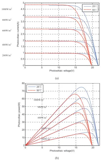
Fig. 2(a) and (b) show the simulated current-voltage and power-voltage (P-V) curves for the PV array at different irradiance level and cell temperatures. From Fig. 2(a), it can be seen that the output characteristics of the PV array are nonlinear under a given temperature and irradiance, which is neither a non-constant voltage source nor a non-constant current one. It is also not impossible to deliver the most preferential output power for load resistance. Practically, the PV array is a nonlinear DC power. And its output current is approximately constant in the most operating voltage range, but declines fast near the open circuit voltage (Voc). From these curves, under a given solar radiation, with a temperature increasing the open circuit voltage (Voc) decreases, and the short circuit current (Isc) slightly increases. Also, under a constant temperature, with a radiation increasing the output current increases and Voc changes little.
0 5 10 15 20 0 0.5 1 1.5 2 2.5 3 3.5 4 4.5 5 Photovoltaic voltage(V) P hot o v ol tai c c ur rent (A ) 25ć 50ć (a) 0 5 10 15 20 0 10 20 30 40 50 60 70 80 Photovoltaic voltage(V) P hot o v ol ta ic po w er (W) 25ć 50ć (b)
Figure 2. The characteristic curves of a PV array. (a) Current-voltage characteristic. (b) Power- voltage characteristic.
In Fig.2 (b), each curve has a maximum power point. When a temperature rises, Voc and the maximum power fall, but the Isc increases slowly. Besides, it can be seen that output power rises to reach its peak then drops with the gradual increase of the output voltage from zero. It is obvious that there is a maximum power output in a given output voltage of solar panel. The I-V characteristic of Fig.2(a) can also illustrate this. Therefore, in order to raise the efficiency of the PV system, an important way is to adjust the output voltage of solar panel in real-time, cause it to work on the maximum power point, which is called maximum power point track (MPPT)
3. MPPT Controller 200W/m2 400W/m2 600W/m2 800W/m2 1000W/m2 200W/m2 400W/m2 600W/m2 800W/m2 1000W/m2
adjust the panel output voltage to a value in which the panel transfers maximum energy to the load by controlling the on-off times of the converter’s power switch transistor. The power delivered to the load is a maximum when the source internal impedance matches the load impedance.
A DC-DC converter with MPPT offers high efficiency over a wide range of operating points. The full power may not be delivered to the load completely due to the power loss for a converter without MPPT. Therefore, the design of a high performance converter is a very important issue.
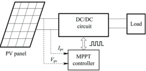
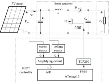
The block diagram of the MPPT controller proposed in this work is shown in Fig.3. A DC-DC converter is used to interface the PV output to the load and to track the maximum power point of the PV array. A more detailed schematic is illustrated in Fig.4. Usually, Topologies of DC-DC converters [5] have mainly buck, boost, buck-boost and Cuk, etc. In this study we chose the boost chopper circuit.
In the controller, the power switch of the converter consists of a power MOSFET. The freewheeling diode D is of a fast switching type. The inductor L is wound on a ferrite-core with air-gap to prevent core
saturation that might be caused by a large DC current component value. C1 and C2 are the input and output
capacitors, respectively; RL is the load; Vpv and Ipv are the voltage and current of the PV array.
A pulse width modulation (PWM) contained by the MPPT controller is used to generate pulse to drive the power MOSFET Qof the boost converter. The switching frequency of power switch Q is equal to 20
kHz. By adjusting the duty cycle of PWM, the converter can draw maximum power from the PV panel. The MPPT controller consists of the three parts:
a) AVR’s ATmega16 low-power consumption, CMOS microcontroller. AVRmega16 is high-performance, 8-bit microcontroller, which is of advanced RISC architecture, 16K bytes of in-system self-programmable flash program memory, 512 bytes EEPROM, 1K byte internal SRAM. A 10-bit 8-channel ADC is used to measure the output voltage and current of PV panel for tracking the maximum power. Two 8-bit timers, one 16-bit timer and four PWM channels are integrated in the microcontroller. Each of the PWM outputs can be used to control a power MOSFET. So it is easy to be programmed and used in data acquisition and control system, and the developing time and expense could be decreased sharply.
b) Interface circuits which comprise of sensors and signal conditioners connected to the microcontroller A/D converter. As shown in Fig.4, the output voltage and current of the PV panel is sampled by using Honeywell’s voltage and current sensors VSM025A and CSM025A, than amplified by operating amplifier to the A/D converter of AVR microcontroller.
c) IC driver for the power MOSFET. TLP250 is used for gate driving of power MOSFET, which consists of light emitting diode and a integrated photodetector.
Figure 4. The MPPT controller
4. The Implementation of Mppt Algorithm
From the current and power characteristics curves, the nonlinear nature of the PV array is obvious. Therefore, an MPPT algorithm must be implemented to force the system to always operate at the maximum power point.
A large number of techniques have been proposed for tracking MPP, as described in Introduction. Two algorithms are commonly used to track the MPPT, which are the P&O method and IncCond method. The P&O method are widely applied in the MPPT controllers due to their simplicity and easy implementation, which compares only two points, which are the current operation point and the subsequent perturbation point, to observe their changes in power and thus decide whether increase or decrease the solar array voltage. The P&O algorithm oscillates around the MPP, resulting in a loss of PV power, especially in cases of rapidly changing solar radiation.
At present, most MPPT algorithms have been suggested. The IncCond method is commonly used in practice. The incremental conductance method is based on the fact that the slope of the PV array power curve (Fig. 2) is zero at the MPP, positive on the left of the MPP, and negative on the right.
Since
dP
dVI
dI
I
I V
I V
dV
dV
dV
V
'
#
'
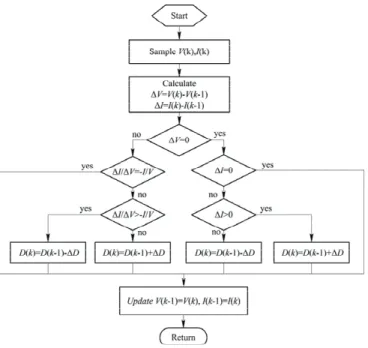
(1) (1) can be rewritten as / , / , / , I V I V at MPP I V I V left of MPP I V I V right of MPP ' ' ° ' ' ! ® °' ' ¯ (2)Figure 5. The IncCond algorithm
The MPP can thus be tracked by comparing the instantaneous conductance (I/V) to the incremental
conductance (ǻI/ǻV) as shown in the equation (2)[6]. The flowchart of IncCond MPPT algorithm is shown in Fig.5, where the converter duty cycle iteration step size is automatically tuned. The PV output power is employed to directly control the converter duty cycle. Note that V(k) and I(k) are the PV array output
voltage and current at time k. In addition, D(k) and ǻD are the duty cycle and change of duty cycle, respectively.
5. Simulation results and discussion
In this study, a STP075S[7] PV module with the surface area of 0.65m2and the conversation efficiency
of 13.1% was used and its nominal maximum power at STC(Irradiance 1000W/m2, module temperature
25°C, AM=1.5) is 75W, Open circuit voltage(Voc) is 21.7V. The input capacitance C1of the boost
converter is 470ȝF, its output capacitance C2 is 330ȝF, and its inductance Lis 54ȝH. In this case, the
proposed control strategy is applied to track the maximum power point of the PV energy system. A corresponding PWM is given by the MPPT controller when the changes of the operating conditions occur. On account of the varying duty ratio of the PWM, the PV array is driven to a new maximum power point by matching the inner resistance of the PV array with the load.
To verify the effectiveness of the proposed IncCond MPPT control algorithm as shown in Fig.5, the PV power system in Fig.4 is modeled and simulated using Matlab/Simulink model. Moreover, the P&O algorithm model is developed. The simulations are configured under exactly the same conditions to compare the performances. The sampling period used for MPPT algorithm is chosen as 0.001s. The duty cycle command is therefore updated every 0.001s. The output power performance of IncCond MPPT with fixed step size of 0.01 under irradiation step change conditions are shown in Fig.6. The irradiation was suddenly changed from 400 to 600W/m2 at 0.4 s and changed to 800 W/m2 at 1s.
In Fig. 6(a) and (b), the power tracking curves are shown at a fixed-step size, and the tracking speed is fast. But in Fig. 6(a), the large oscillation occurs near the maximum power point and the system has a greater power loss. With the various surrounding conditions, as Fig. 5(b) shown, the IncCond method achieves lower oscillation around the MPP than the P&O method.
0 0.5 1 1.5 25 30 35 40 45 50 55 60 65 Time(s) P V ou tp ut po w e r( W )
Irradiation step change 400 to 600W/m2 at 0.4s 600 to 800W/m2 at 1.0s (a) 0 0.5 1 1.5 0 10 20 30 40 50 60 70 Time(s) P V ou tp ut p ower(W)
Irradiation step change 400 to 600W/m2 at 0.4s 600 to 800W/m2 at 1.0s
(b)
Figure 6. The output power tracking curves of the PV system. (a) the tracking curve of the P&O method. (b) the tracking curve of the IncCond method
6. Conclusions
Because of the nonlinear characteristics of solar cells, it is necessary that a energy control circuit must drive the PV module for the maximum power. A solar MPPT controller based on an incremental conductance algorithm is designed for a PV energy system; the MPPT controller based on AVR ATmega16 microprocessor, change the duty cycle of PWM of the boost converter circuit. Result shows the MPPT controller can fast track the maximum power point by using IncCond method, has better response and lower oscillation under rapid atmospheric conditions.
Reference
[1] Chihchiang Hua, Jongrong Lin and Chihming Shen, “Implementation of a DSP-Controlled Photovoltaic System with Peak Power Tracking”, IEEE Trans.On Insustrial Electronic, vol.45, pp.99–107, February 1998.
[4] Zhao zhengming and Liu Jianzheng, Solar photovoltaic power generation and its application, Beijing: Science Press, 2005, pp.110-130.
[5] Wang Zhaoan and Huang Juan, Power electronic technology, Beijing: Machine Press, 4rd ed.,2000, pp. 100–105.
[6] Trishan Esram and Patrick L. Chapman, “Comparison of Photovoltaic Array Maximum Power Point Tracking Techniques”. IEEE Trans. ON Energy Conversion, VolL. 22, NO. 2, June 2007, pp: 439-449