DigitalCommons@University of Nebraska - Lincoln
DigitalCommons@University of Nebraska - Lincoln
Computer Science and Engineering: Theses,
Dissertations, and Student Research Computer Science and Engineering, Department of
8-2012
Routing over the Interplanetary Internet
Routing over the Interplanetary Internet
Joyeeta MukherjeeUniversity of Nebraska-Lincoln, [email protected]
Follow this and additional works at: https://digitalcommons.unl.edu/computerscidiss
Part of the Computer Engineering Commons, and the Computer Sciences Commons
Mukherjee, Joyeeta, "Routing over the Interplanetary Internet" (2012). Computer Science and Engineering: Theses, Dissertations, and Student Research. 42.
https://digitalcommons.unl.edu/computerscidiss/42
This Article is brought to you for free and open access by the Computer Science and Engineering, Department of at DigitalCommons@University of Nebraska - Lincoln. It has been accepted for inclusion in Computer Science and Engineering: Theses, Dissertations, and Student Research by an authorized administrator of
by
Joyeeta Mukherjee
A THESIS
Presented to the Faculty of
The Graduate College at the University of Nebraska In Partial Fulfilment of Requirements
For the Degree of Master of Science
Major: Computer Science
Under the Supervision of Professor Byrav Ramamurthy
Lincoln, Nebraska August, 2012
Joyeeta Mukherjee, M. S. University of Nebraska, 2012
Adviser: Byrav Ramamurthy
Future space exploration demands a Space Network that will be able to connect spacecrafts with one another and in turn with Earth’s terrestrial Internet and hence efficiently transfer data back and forth. The feasibility of this technology would enable common people to directly access telemetric data from distant planets and satellites. The concept of an Inter-planetary Internet (IPN) is only in its incubation stage and considerable amount of common standards and research is required before widespread deployment can occur to make IPN feasible.
We provide a comprehensive survey that presents a picture of the current space networking technologies and architectures. In the survey, we discuss the IPN and Delay Tolerant Net-working (DTN) concepts along with the various space networks that are currently deployed. We next propose a design of the IPN and implement it with the Interplanetary Overlay Network (ION) software module on real time physical nodes on the ORBIT testbed. Two space network scenarios are designed and experimentally evaluated to verify the correctness of the network implementation. We also focus on the study of bundle transmission delay and separately evaluate the effect of bundle size and number of bundles. The experimental evaluation provides insights into the factors which caused delay in bundle transmission such as custody refusal, expiration of bundle lifetime and congestion.
ACKNOWLEDGMENTS
First of all, I would like to express my appreciation to my advisor, Professor Byrav Rama-murthy for his guidance, encouragement and continuous support throughout the course of my master’s study and research. His support has always been very generous in both time and research resources. His technical and editorial advice and infinite patience were essential for the completion of this thesis.
Besides my supervisor, I would also like to thank the rest of my thesis committee, Professor Jitender Deogun and Professor Lisong Xu for their invaluable time and their thoughtful and critical reading of this thesis. Their involvement has greatly improved and clarified this work. I would like to thank all the CSE staff and friends and everyone who has helped me along the way, for their friendship and for all the memorable times at UNL. I thank Dr. Loren P. Clare and Mr. Philip C. Tsao (both of NASA, JPL) as well as Mr. Ivan Seskar (Rutgers Univ.) for sharing their expertise on Space DTN and ORBIT testbed respectively. I also thank the financial grant support in part by an NSF FIA grant (CNS-1040765) and a NASA Nebraska Space Research Mini-Grant.
This thesis is a dedication to my parents Mr. Sanjoy Mukhopadhyay and Mrs. Sujata Mukhopadhyay without whom I would have never been able to reach this stage. Their love and sacrifice and their strong belief in me have truly pushed me throughout my academic years. I would also like to thank my younger brother who in his own way gave me little encouragements and joy to move on. Last but not the least I would specially thank my husband Dr. Tathagata Mukherjee, without whose love and support none of this would have been possible.
Contents
List of Figures vi
List of Tables viii
1 Introduction 1
1.1 Space Network Technologies . . . 1
1.2 Space Communication parameters . . . 3
1.3 Space Communications Protocols. . . 4
1.4 ORBIT testbed and Interplanetary Overlay Network (ION) . . . 6
1.5 Motivation . . . 6
1.6 Contributions . . . 9
1.7 Outline. . . 10
2 Delay Tolerant Networking (DTN) 11 2.1 Introduction . . . 11
2.2 Terrestrial DTN . . . 13
2.3 Space DTN . . . 16
2.3.1 Recent Experiments on Space DTN . . . 21
2.3.1.1 UK-Disaster Monitoring Constellation (UK-DMC) . . . . 21
2.3.1.3 Experiment on-board the International Space Station (ISS) 23
3 Background and Experimental Setup 25
3.1 Interplanetary Overlay Network (ION) . . . 25
3.2 ORBIT Testbed . . . 28
3.3 Experiment Environment Setup . . . 30
4 Experiments and Results 35 4.1 Introduction . . . 35
4.2 Network Scenario . . . 35
4.2.1 Scenario 1: Lunar Mission . . . 35
4.2.2 Scenario 2: Mars Mission. . . 36
4.3 Experimental Results . . . 38
4.3.1 Verifying Network Operation . . . 38
4.3.2 Studying Bundle Transmission Delay . . . 40
4.4 Summary . . . 47
5 Conclusion and Future Work 50 5.1 Conclusion . . . 50
5.2 Future Work . . . 51
A List of Acronyms 53
B Installing ION software module 56
C Preparing ORBIT testbed for Experiment 59
D C Program for Bundle Transmission 61
List of Figures
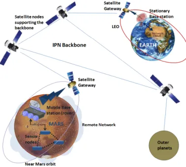
1.1 A graphical representation of future Deep space architecture that portrays re-mote planetary networks communicating with Earth based Internet. The rere-mote network chooses among mobile satellite gateways to hook up to the IPN back-bone. The satellite gateways in turn act as an interface between the remote network and the backbone. . . 2
1.2 Software Architecture of ORBIT Testbed. . . 7
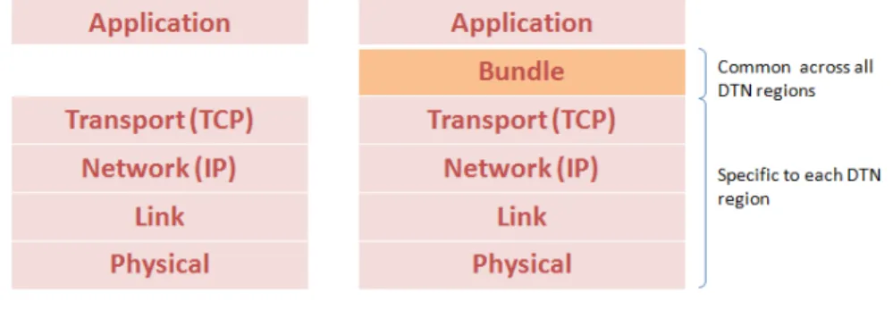
2.1 Comparison of Internet protocol layers to DTN protocol layers. . . 11
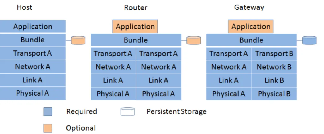
2.2 DTN nodes may be a host, router or gateway acting as a source, destination or forwarder. . . 14
2.3 The two basic Bundle Protocol block Formats (redrawn from [37]). . . 18
2.4 Example of the SDNV encoding scheme for hexadecimal number 0x4234. . . . 19
2.5 An example of DTN Implementation Architecture : The architecture shows how a bundle forwarder interacts with the other components and utilizes various protocols for data transmission (adapted from [15]). . . 20
2.6 Use of Bundling and fragmentation over a number of passes of the satellite. . . 22
3.1 ION Software Functional Dependencies. . . 27
3.2 ORBIT Experiment support architecture. . . 28
3.4 Configuration File for 2 Node Communication using UDP . . . 32
3.5 Ruby script file to start ION Application . . . 34
4.1 Scenario 1 depicting the Earth to Moon communication configuration. . . 37
4.2 Contact graphs for Scenario 1: Lunar Mission. . . 37
4.3 Scenario 2 depicting the Earth to Mars communication configuration.. . . 39
4.4 Contact graphs for Scenario 2: Mars Mission. . . 40
4.5 Test A: Network statistics for transmitting 4 bundles. . . 41
4.6 Test B: Network statistics for transmitting 7 bundles. . . 42
4.7 The status of the bundles in the network and their corresponding counts. . . 43
4.8 Transmission Delay of Bundles through the DTN. . . 44
4.9 Bundle Transmission Delay with varying bundle size. . . 45
4.10 Variation in Scenario 1 by adding extra nodes. . . 46
4.11 Bundle Transmission Delay with varying bundle size along with the implemen-tation of extra nodes. . . 48
4.12 Transmission Delay of Bundles through the DTN. . . 48
B.1 Commands to install Expat XML parser. . . 57
B.2 Commands to install the ION software module. . . 57
C.1 Commands to prepare ORBIT for experimentation. . . 60
D.1 Commands to compile and execute send/receive applications. . . 61
D.2 The send Application code. . . 62
List of Tables
1.1 Classification of Space Communication Protocols (Adapted from [42]). . . 5
1.2 Summarizing the differences between Terrestrial Internet and IPN. . . 8
3.1 Divisions of ION Infrastructure. . . 26
3.2 Ephemeris data sample for MRO. . . 31
3.3 Ephemeris data sample for the different MRO structures. . . 31
3.4 Ephemeris data label. . . 33
4.1 Description of different network activities for an ION implementation. . . 41
4.2 Bundles sent at different time slots (in hours:minutes) for Scenario 2: Mars Mission. . . 42
Chapter 1
Introduction
Space communication and networking research has added a new engineering and scientific era to the history of space exploration. The early phase of space communication used radio signal shot towards spacecraft antennas whenever they came into view. Telecommunications software lacked universality and differed from one mission to another. This, in turn, led individual flight projects to acquire and operate their own specialized space communication network. The immediate answer was to develop a space network that can be interconnected, standardized and evolved over the future decades. Such motivations led to the development of various networking architectures and technologies that could support space communication networks - such as the Deep Space Network (DSN), Interplanetary Internet (IPN), Delay tolerant Networking (DTN) and so on.
1.1
Space Network Technologies
Several satellites from different government space agencies and even private companies have been deployed in orbit over the past decades. As the number of space agencies started to increase, common standards were adopted so as to promote collaboration. The International
Figure 1.1: A graphical representation of future Deep space architecture that portrays remote planetary networks communicating with Earth based Internet. The remote network chooses among mobile satellite gateways to hook up to the IPN backbone. The satellite gateways in turn act as an interface between the remote network and the backbone.
Space Station (ISS) is a very good example of such efforts. Moreover, with increasing deployments the IPN can gradually build up its backbone to help communicate with the far reaching planets of the solar system. Figure1.1shows a graphical representation of the future where Earth based Internet will connect with remote networks of the solar system using satellite gateways and the IPN backbone. The remote networks will support different protocols and will connect to the backbone by choosing among satellite gateways that would seamlessly convert between these protocols. However, the present scenario is quite different from this futuristic vision. Today one cannot support an Earth orbiting spacecraft (relay) to a Mars orbiting spacecraft (relay) link, because the cost of constructing transceivers sensitive enough to receive/transmit signals over such large distances is so great that it is impractical to place such transceivers in orbit. We are still awaiting for specific innovations that would make Space Networks feasible in the near future.
Enormous amounts of critical data are returned from satellites and space missions every day. They need to be efficiently handled and stored. Horizons [21] is an online data and ephemeris computation service provided by the Solar System Dynamics Group of the NASA Jet Propulsion Laboratory (JPL), based in Pasadena, CA. An ephemeris is a tabulation of computed positions and velocities (and/or various derived quantities such as right ascension and declination) of an orbiting body at specific times [20]. Underlying these applications we have the Planetary Data System (PDS) of NASA [26] which is an archive of data products from NASA planetary missions.
1.2
Space Communication parameters
Space communication parameters are very specific to a mission and the operation or service required and also on the system which provides the service. The National Aeronautics and Space Administration (NASA) presently operates and maintains three separate tracking networks to support different types of missions - Deep Space Network (DSN), Near Earth Network (NEN) and the Space Network (SN). The DSN supports both Earth orbiting and deep space science missions while the NEN supports non-deep space missions in the 2 and 8 GHz bands range. The Space Network (SN), otherwise known as the Tracking and Data Relay Satellite System (TDRSS) consists of seven geosynchronous satellites and ground stations that together operate in the 2, 13-15 and the 26 GHz band. The prime goal is to increase the data rates of satellite communication systems. SN is capable of data rates on the S-band (6 Mbps) and Ka-band (800 Mbps) Single Access (SA) channels. Among the three tracking networks, we concentrate on DSN communication which provides command, telemetric and tracking services to a large number of space missions.
Each service in DSN has its own parameter specifications. The command services of DSN mainly use the S and X band frequencies with Binary Phase Shift Keying (BPSK)
modulation schemes. The 70 m antenna used for major space communications has a maximum transmitting power of 20 kW with a maximum uplink data rate of 256 Kbps and a minimum of 7.8 bps. The data unit size is a maximum and minimum of about 32,752 bits and 16 bits respectively. Bit error rate for command services depends on a presumed signal to noise ratio at the spacecraft and is around10−7and the service availability moves within 95 to 98 percent at all times. For telemetric services, both near-Earth and deep space missions use the S, X or the Ka band frequencies for communication. Modulation schemes can be Phase Shift Keying (PSK), Binary Phase Shift Keying (BPSK) or Quadrature Phase Shift Keying (QPSK). Downlink data rates are a maximum of 6 Mbps for deep space missions and 125 Mbps for near-Earth missions and a minimum of 10 bps. The data unit size and transmitting power depends on further sub-division of telemetric service types and can be found in [19]. Service availability is the same as that of command services while the frame rejection rate is about10−4to10−5which in turn determines the data quality. More detailed information about cost and parametric values can be found in [19] which can give us a clear idea about communication specifications for space networks.
1.3
Space Communications Protocols
The Space Communications Protocol Specifications (SCPS) are a set of extensions to the already existing protocol set and new protocols that are developed by the Consultative Committee for Space Data Systems (CCSDS) [1] for implementation and to improve the per-formance of Internet protocols in space environments. The SCPS protocol stack contains the SCPS-FP (extension of the File Transfer Protocol), SCPS-TP (extension and modification of the Transfer Control Protocol), SCPS-SP (security Protocol) and the SCPS-NP (a bit efficient network protocol). All of these protocols are used for different application environments. Some are for near-Earth satellites while others are for deep space communication but almost
all of them solve the major problems of space communication - high Bit Error Rate (BER) and long link delays. In [42] the authors have broadly classified the space protocols into three categories as shown in Table1.1based on current terrestrial Internet protocols and their application. A protocol called the Deep-Space Transport Protocol (DS-TP) have been proposed in [34] and its main advantage has been identified as its capability of transferring complete files faster than TCP, SCPS-TP [28] or the Saratoga protocol [44]. The LTP (Licklider Transmission Protocol) is another Delay Tolerant point-to-point Network protocol for space communication, which provides retransmission based reliability over links which are characterized by extremely long round-trip times (RTT). The choice of a particular space protocol depends on numerous architectural and mission specific constraints. The authors of [11] discuss a number of considerations while selecting a communication network protocol for deep space.
Table 1.1: Classification of Space Communication Protocols (Adapted from [42]).
(1) Changes to TCP SCTP (Stream Control Transmission Pro-tocol) [38], STP(Satellite Transport Proto-col) [17], XSTP (Extended STP) [13], TCP Peach [3], TP-Planet (Transport Protocol-Planet) [2], TCPW (TCP Westwood) [7] (2) Changes to TCP and/or
Network Infrastructure
XCP (Explicit Congestion Control) [23], P-XCP (Proportional XCP) [45], REFWA (Recursive, Explicit and Fair Window Ad-justment) [40], SCPS-TP (Space Communi-cation Protocol Standard-Transport Proto-col) [28], I-PEP (Interoperable PEP) [36], PETRA (Performance Enhancing Transport Architecture) [24]
(3) Delay Tolerant Network-ing (DTN)
BP (Bundle Protocol) [37], CFDP (CCSDS File Delivery Protocol) [29], LTP (Licklider Transmission Protocol) [6]
1.4
ORBIT testbed and Interplanetary Overlay Network
(ION)
The ORBIT (Open Access Research Testbed for Next-Generation Wireless Networks) testbed [43] is a radio grid which is used for next generation wireless networks and protocols, developed and maintained by WINLAB in Rutgers University. Wireless network experiments can be conducted on the testbed on site or through remote access. It maintains a database to store information during an experiment which can be later retrieved for study and analysis. The general software architecture of the ORBIT testbed is shown in Figure1.2. ORBIT is a 20 x 20 radio grid and for our experiment purposes we used a subset of all the nodes to emulate a space network of satellites and Earth stations. At the Application layer each of the nodes run the Interplanetary Overlay Network (ION) software module which is developed by JPL, NASA as an implementation of the DTN architecture and is intended to be useful for interplanetary communication. ION is mainly used to induce DTN functionalities into robotic spacecrafts keeping in mind the various constraints in automated digital data communication networks spanning space links, planetary surface links, and terrestrial links. The details of ION and ORBIT will be discussed in Chapter3.
1.5
Motivation
This thesis focuses on developing a better understanding of Interplanetary Internet (IPN) and studying delay while routing a bundle over the IPN. The IPN is a still-to-be-implemented computer network in space. It is a store and-forward network of Internets in support of deep space exploration that is often disconnected, has a wireless backbone with error-prone links and delays ranging to tens of minutes, even hours, even when there is a connection. The round trip times can be as large as 40 minutes long for the cis-Martian (on the near side of)
Figure 1.2: Software Architecture of ORBIT Testbed.
channel and even more than 100 minutes for a channel from Jupiter to Earth [42]. Terrestrial Internet technologies do not seem feasible for such harsh environments. Moreover, the IPN backbone is quite different from the terrestrial Internet as we have summarized in Table1.2. Further communication problems may arise when connections between traffic hubs in an IPN is interrupted when planetary rotation or orbital motion takes a transmitting entity out of the line-of-sight (LOS) to the receiving entity. There may also be extreme environmental conditions such as solar storms and magnetic interferences that challenges network commu-nication. The existing terrestrial Internet and the TCP/IP suite will not be able to handle the constraints (like long and variable delay, frequent network partitioning, data rate asymmetry and packet loss and errors [8]) posed by such extreme conditions. Moreover, the power availability is extremely limited in spacecrafts, and even worse that the spacecrafts which are farther away from Earth have back dated technology than the ones launched recently. This imbalance in resource towards the critical end makes the challenge even bigger. In 2002, Kevin Fall started to adapt some of the ideas of the IPN to terrestrial network and
Table 1.2: Summarizing the differences between Terrestrial Internet and IPN.
TERRESTRIAL INTERNET IPN
Power Availability Not critical Of Overriding importance
Delay 0.1 sec 10 to 10,000 seconds
Signal to Noise ratio For wired network it’s quite high. For Terrestrial MANET, SNR is low and it’s a function (power, node den-sity).
Very low SNR and it’s a function (power).
Infrastructure Fixed or may be mobile Always deployable and mobile Transmission Medium Copper or Fiber, FSO, RF, IR Primarily Free Space - Laser or RF,
causes high BER.
Deployment Cost Relatively low or moderate High and is a function (mass) Operations Cost Relatively low High and is a function (reliability) Repair and Upgrade Cost Relatively low Very High
first coined the term Delay Tolerant Networking (DTN) and its motivation is made clear in [14]. Recently, several tests have been made with the DTN in space that has verified the feasibility of IPN. The experiments were carried out with real time satellites and ground stations and they validated the DTN Bundle protocol and the Interplanetary Overlay Network (ION) software which is an implementation of the DTN architecture. However, there has not been any efforts to test the feasibility of IPN on terrestrial network testbeds. It is far more easier to implement and test the different topologies and DTN operations while using a terrestrial network testbed. Moreover, testing environments are not yet well developed for space implementations. It is not cost-effective and the need is very small. With terrestrial testing environments we can easily deploy a satellite as a simple computer node and emulate communication parameters and delay to test operations of a space network.
Delay is the most important factor in space communication and as we have seen before the nature is very different from terrestrial delay environments. Space deployments are also
very costly and it is a one time effort. Considering these critical issues it becomes important to design the deployments very carefully so as to bring down delay as much as possible. Once we validate a topology, we try to understand the factors that affect the transmission delay in order to gain insight into IPN deployments.
1.6
Contributions
In this thesis, we present an emulation based approach to examine the feasibility of space communication using JPL’s ION software with two scenarios each portraying a different topology. We design an alternate path topology with 4 nodes for communication between Earths’ Deep Space Network (DSN) and a Moon based station and our second topology considers 6 nodes to allow communication from DSN stations to a Mars based network. These two topologies help us to test the DTN functionalities like forwarding, custody transfer, data bundling and routing over the DTN network. We consult the ephemeris data from NASA’s Horizons system [21] to design our contact graphs and then implement the ION software on each node. Once the network is setup the contact graphs control the communication routes over the entire duration till we again tear down the network. While the network is alive we consider each node moving in and out of sight with one another while huge propagation delay (a maximum of 324 seconds) is induced between every communicating node. We transmit small as well as large bundles to test the capacity of the links as well the nodes and in turn examine the delay of receiving an entire bundle at the destination. We conduct all our experiments over a terrestrial based testbed which also gives us an insight on how to setup space networks on terrestrial environments. Based on our implementation of ION based DTN architecture, we derived insights into what factors caused delay in communication such as large bundle size, more number of hops due to extra nodes and increase in the number of bundles.
1.7
Outline
This thesis has been organized as follows. Chapter2presents the general DTN functionali-ties for terrestrial networks and discusses DTN for space based communication networks. Chapter3discusses ION software and the ORBIT testbed and then explains the experimental setup. Chapter4describes the emulated experiments and analyses the experimental results and finally Chapter5concludes the thesis and describes possible future work.
Chapter 2
Delay Tolerant Networking (DTN)
2.1
Introduction
Delay Tolerant Networking (DTN) can be viewed as an overlay network on top of regional networks. It incorporates a new protocol layer called as the bundle layer on top of hetero-geneous region specific lower layers. Figure2.1shows the difference between our present terrestrial Internet layers and the DTN layers.
A number of protocols have evolved from the existing Internet protocol suite to support the DTN architecture and have focused on specific DTN characteristics. The DTN transport
protocol does not involve an end-to-end communication like Transmission Control Protcol (TCP), instead it employs a store and forward approach where the data is stored and moved incrementally throughout the network in the hope that it will finally reach its destination. Another approach can be to send the message repeatedly so that at least one copy reaches the destination. In the second approach more amount of local storage and internode bandwidth is required [35]. DTN itself primarily speaks of delay in a network which can be of three major kinds: propagation delay through the medium; queuing delay within relay points, source, and destination; and clocking delays associated with transmitting an atomic unit of data onto the medium [8]. Propagation delays over the medium can be long due to speed-of-light delays to cross long distances (e.g., deep space). It could also be long due to the propagation medium (e.g., acoustic/underwater). On the other hand queuing delays within relay points are affected by traffic and service rate. Nodes in a DTN can have scarce power supply, for example solar charged battery which might not be enough to run a fast processing unit, thus leading to data queues. Clocking delays occur when an erroneous data is received but it is not recognized and resent until the whole data is fully received. In a slow multi-hop network, the per packet delay can be quite large for big packets. Another contributor to overall delay mechanism is the processing delay which is comparatively low. However, sometimes it becomes a noticeable factor in the overall delay.
Research in DTN has been covering a vast range of environments and each of the entities in the environment have their own set of characteristics and features. For example, each node or hub in space network might have different resource capability which will govern the way in which they will transmit among each other. They will also have to balance their various functionalities – a Mars rover that is destined to collect samples during a red sandstorm might not be able to process and relay signals during that time. Moreover, the time for which two entities remain within line-of-sight is pretty fixed and the duration is known in advance. Hence, transmissions can be scheduled beforehand and routing decisions is not the
major player. This might not be the case for other environments like a vehicular DTN or underwater environments. Hence, the DTN protocol is very much application specific. Study of a DTN system has been separated into two broad categories –DTN service targets
andSystem constraints[35]. Service target refers to delivery ratio which informs us about
the reliability of the system and delivery delay that is actually the latency to be accounted for. System constraints include the storage space availability and energy constraints of the network, given that we mainly work with mobile and battery powered devices in a DTN [35]. Based on these characteristics of the system, DTN has been categorized as terrestrial and space based networks, which we briefly discuss in the following two sub-sections.
2.2
Terrestrial DTN
Several Earth-based applications that need to survive and communicate in harsh environ-ments have implemented the DTN technology. A few of them are - tracking of wildlife, military operations, underwater communication, enhancing Internet “hotspot” connectivity in rural areas in third-world countries and so on. All of these environments have one thing in common and that is a large amount of delay in transmission, which encourages data storage at nodes in the network. One good example of terrestrial DTN implementation is DakNet [33] which has been able to provide connectivity in remote villages of developing countries such as India and Cambodia. The DakNet wireless network takes advantage of the already functional communication and transportation infrastructure. There are several other implementations of DTN like ZebraNet [22], UMassDieselNet [4] which proposes MaxProp, a protocol for effective routing of DTN messages. DriveThru [32] is another kind of DTN that provide hotspots at every street corner so that mobile users can access them to obtain intermittent connectivity and acquire local updates as well as Internet access. All these networks are propped by the DTN architecture and they try to resolve problems in
Figure 2.2: DTN nodes may be a host, router or gateway acting as a source, destination or forwarder.
Earth based challenged environments. We discuss and summarize the major features of the DTN architecture below:
• A DTN-enabled application sends messages known as Application Data Units or ADUs, in complete units.
• At the bundle layer the ADUs are transformed into Protocol data units called “bundles” which is then stored and forwarded by the DTN nodes. Bundles can further be broken into bundle fragments and also reassembled as and when required during transmission. Fragmentation can be done pro actively or reactively [9] such that partially forwarded bundles are not retransmitted.
• An End Point Identifier (EID) identifies a bundle source and destination and it is expressed syntactically as a Uniform Resource Identifier (URI).
• An EID may also refer to more than one DTN nodes for multicast destinations. • A DTN node may act as a host, router or a gateway. A host can only be a source or
a destination for bundle transfer. It sometimes might need a persistent storage and optionally supports custody transfer. On the other hand a router forwards a bundle
within a single DTN region and may optionally act as a host. It requires a persistent storage in case of long delay links and sometimes supports custody transfer. The gateway also acts as a forwarder but between two or more DTN regions and may optionally be a host. They always require a persistent storage and supports custody transfers. Gateways mainly provide conversions between the DTN regions. Figure2.2
shows the differences between various kinds of DTN nodes.
• The DTN architecture has remodeled the URI scheme giving it a lot of flexibility. It can be constructed based on DNS names, or it can be database queries or even intentional names or expressions [10]. For example, we can have EIDs such as “dtn://myMachine/dtntrans” and “dtn://everyoneWithinArea1000miles”
• A priori knowledge of the bundle’s size and service requirements are provided to aid the bundle layer with routing decisions.
• DTN supports late binding, which means that binding a bundle’s destination to a particular set of bundle identifiers may take place at the source, in transit or at the destination. This in unlike the Internet’s early binding approach. It is advantageous because the delay in such architecture may exceed the time of binding validity. More-over, resources are limited and this approach considerably reduces administrative and mapping overhead.
• The DTN architecture defines three priority classes that guides the routing and schedul-ing algorithms - Bulk, Normal and Expedited.
• Delivery options such as custody transfer request, report when bundle delivered, deleted or forwarded, confidentiality, authentication or error detection request and so on are supported by the architecture which gives the applications much more flexibility.
• Administrative records are used to report bundle status and custody signals.
• The DTN can be represented as a multigraph where vertices may be interconnected with more than one edge. An edge can have significant amount of delay and constant capacity and when the capacity is strictly positive the period of time is called as a “contact”. Contacts are classified into a number of types based on their performance
characteristics [9].
• DTN also implements end-to-end reliability/ acknowledgments for the applications that would request for it. However, it pushes the responsibility or transfers custody of a bundle towards its destination.
• Time synchronization and time stamps become important for DTN networks in order to identify bundle and fragments for routing, bundle expiration time computations and application registration (registering to the network so that it can accept ADUs destined for a DTN endpoint with an EID) expiration.
• Security in terms of Denial of service have also been considered within the architec-ture.
Armed with an overview of the Terrestrial DTN architecture, we move on to space DTN systems and experiments which is further challenged by a totally different environment from terrestrial applications.
2.3
Space DTN
The most important motivation for DTN use in space communication, results from making IPN a real networking environment. In a terrestrial DTN when a connection is set up there is no way that an enormous delay can occur (delay is then limited by Earth based Internet
speeds). On the other hand in space DTN architectures, even when there is a full connection, delays can be huge. This makes them very different from terrestrial DTN architecture. In space DTN, certain issues such as routing and storage congestions have not been researched until now because routing paths and duration of connectivity are always known in advance. Moreover, it is a sparse network with only a handful of relay nodes. The Internet Research Task Force (IRTF) DTN Research Group (DTNRG) has investigated more into security and transport layer issues. As an outcome we have the Bundle Protocol that sits in the Application layer of our current Internet model. The important capabilities of the protocol can be summarized as below and is stated in [37]
• Custody-based retransmission
• Ability to cope with intermittent connectivity
• Ability to take advantage of scheduled, predicted, and opportunistic connectivity (in addition to continuous connectivity)
• Late binding of overlay network endpoint identifiers to constituent Internet addresses In this section we introduce the terms associated with the Bundle Protocol mechanism. More information about DTN based space protocols can be found in [30]. The Bundle Protocol uses the ‘native’ Internet protocols (not necessarily TCP/IP) to communicate within the Internet. The Convergence Layer Adapter (CLA) forms an interface between the Bundle Protocol and a common internetwork protocol and it offers important functions to the Bundle Protocol Agent (BPA) – a part of the node that provides Bundle Protocol services. More about the CLA services is mentioned in [37]. A bundle node is the one that sends or receives data. It can be a thread running on the system, an object in an object oriented programming environment or may be a special purpose hardware device. The bundle endpoint is a group of such bundle nodes that can offer Bundle Protocol functionalities and they identify
them-(a) Primary Bundle Block format
(b) Bundle Payload Block format
Figure 2.3: The two basic Bundle Protocol block Formats (redrawn from [37]).
selves with a single string called as the “bundle endpoint id”. The bundle endpoint can be a single node or a single bundle node can also be a part of many endpoints. Whenever a bundle node decides to forward a bundle it does so and marks the destination as the bundle endpoint.
The Bundle Protocol data unit is referred to as a “bundle” and it contains at least 2 or more blocks of protocol data. The first one is called the primary bundle block and it may be followed by sequence of Bundle Protocol blocks that can be used to support Bundle Protocol extensions such as the Bundle Security Protocol (BSP) [39]. Among them there must be at most one block that acts as the payload block. The ending block in the sequence
must have the “last block” field set to 1, which will indicate it as the last block. Figure2.3a
and 2.3bshow the primary and the payload bundle block respectively [37]. The Bundle Protocol tries to use as minimum bandwidth as possible while transmission. This has been accomplished with the help of Self-Delimiting Numeric Values (SDNV) encoding technique. In this technique any positive numeric value is encoded into N octets, the Most Significant Bit (MSB) of the last octet is set to 0 while all the other octets have their MSBs as 1. The other 7 bits of every octet contain relevant information. An example of the encoding scheme is shown in Figure2.4for hexadecimal number 0x4234.
Figure 2.4: Example of the SDNV encoding scheme for hexadecimal number 0x4234.
The Bundle Protocol of DTN architecture has always considered security as a very important aspect of its design. The DTN environment has very limited resources, such as scarce band-width, small storage available at nodes and intermittent connectivity. To cope up with it the Bundle Protocol allows only authorized users to send bundles over the network. Moreover the environment has large delays where data resides on various nodes for comparatively long period of time and hence the sender should be even more concerned about data integrity and confidentiality. All the internal bundle-aware overlay networks should be able to send data over the nodes preserving data security. There are three securityspecific bundle blocks -the Bundle Au-thentication Block (BAB) that provides au-thenticity and integrity to bundles on a hop-by-hop basis, the Payload Security Block (PSB) provides bundle authenticity and integrity from “security-source” to “security-destination” (A “security source” may not be the actual point of origin of the bundle but instead it is the first point of security awareness
Figure 2.5: An example of DTN Implementation Architecture : The architecture shows how a bundle forwarder interacts with the other components and utilizes various protocols for data transmission (adapted from [15]).
in the network) and finally the Confidentiality Block (CB) provides payload confidentiality. Details about the security blocks can be found in [37] and [39]. The generic Internet also has another common security issue known as the denial-of-service attack which the DTN architecture robustly defends. [41] elaborates a few possible denial-of-service attacks against DTN and also proposes a set of countermeasures in accordance with the author’s model. Security issues related to space DTN have been discussed in more details in [16].
In Figure2.5we have shown an implementation architecture for DTN where we have a cen-tral bundle forwarder, which can be the Bundle Protocol Agent (BPA) of a node to forward bundles (based on routing algorithm decisions) to the Convergence Layer Adapter (CLA), storage or local application. The arrows represent interfaces through which the bundle forwarder interacts with the applications, CLAs and management processes. Implementing these interfaces using inter-process communication rather than normal procedure calls has been quite beneficial for the development of the architecture. These interfaces carry bundles or directives that are represented as tiny green and yellow boxes respectively. The native
Internet protocols provide different semantics that is not helpful to the DTN architecture. It is the task of a group of protocol-specific CLAs to provide the necessary functionalities required to carry the bundles on each of the required protocols [15]. Next in Section2.3.1
we describe the recent experiments on space DTN architecture.
2.3.1
Recent Experiments on Space DTN
2.3.1.1 UK-Disaster Monitoring Constellation (UK-DMC)
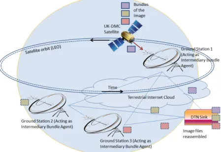
The Bundle Protocol intended for IPN was first tested and demonstrated on board the UK-DMC satellite built by Surrey Satellite Technology Ltd (SSTL) on August, 2008. The transfer process did not have high propagation delays, but instead it was intended to check the proactive fragmentation capabilities of the Bundle Protocol which would even allow a large file to be sent over the network during a single contact opportunity to a ground station. There are seven UK-DMC imaging satellites in the Low Earth Orbit (LEO) which have 5 to 14 minutes of contact time during a scheduled pass to a ground station (ground stations are interconnected through terrestrial networks), in its complete 100 minute orbit [18]. The image taken by the satellite was broken into bundles and required three passes to be transferred to the ground and finally to a “DTN sink” as demonstrated in Figure 2.6. If the satellite were to transfer it to a single ground station it would take approximately three orbits for a sink to obtain the complete file (considering minimum delays over the terrestrial network). The UK-DMC satellite did it in only one orbit by transferring the image bundles to separate ground stations and then reassembled it over the terrestrial Internet at the sink using the Bundle Protocol of DTN architecture.
Figure 2.6: Use of Bundling and fragmentation over a number of passes of the satellite.
2.3.1.2 Deep Impact Network Experiment (DINET)
On October and November 2008, NASA performed its first test with DTN in close coopera-tion with the Epoxi project. The experiment (mainly performed to simulate a Marslocal
planet network) was called the Deep Impact Network Experiment (DINET), and almost
300 images were sent to the spacecraft from various JPL nodes over a period of 1 month. Demonstrations were performed twice a week. The complete network constituted of 10 nodes [27] - One is the Deep Impact Epoxi spacecraft (that is located at 80 lightseconds from Earth and acts as Mars relay orbiter) itself and the other nine are on the ground at JPL and they simulate Mars landers, orbiters and ground mission-operations centers.
The course of the experiment is summarized below:
• October 18, 2008 - The Interplanetary Overlay Network (ION) DTN software (ex-plained in Chapter3) was successfully uploaded on the Epoxi spacecraft and data was sent and received from the DINET Experiment Operations Center.
same images were transmitted and successfully received at JPL over the first instances of IPN.
• October 22, 2008 - During pass 2 of the experiment 264046 bytes (five images) were successfully delivered making 97.6% (approx) link utilization.
• November 3, 2008 - On the 5th DSN tracking pass an additional 1587420 bytes (35 image files) were delivered via the IPN to image reception software in the DINET Experiment Operations Center.
2.3.1.3 Experiment on-board the International Space Station (ISS)
NASA’s Huntsville Operations Support Center (HOSC) has also been testing the DTN technology on the International Space Station (ISS) in collaboration with University of Colorado. It has deployed the Bundle Protocol in a Bundle Protocol Agent (BPA) to the Commercial-Grade Bioprocessing Apparatus 5 (CGBA5) and carried out a series of tests. The CGBA5 is primarily an environmental control chamber for life science experiments but along with that it also provides a computational/communication platform. The uplink and downlink bandwidth provided by the channel is 150 and 400,000 bits per second. There’s an uplink via S-band and two downlink paths: S- and Kµ-bands. The S-band is viewed as the
primary payload uplink and telemetry downlink path with relatively low data and command rate such that the bandwidth and command slots are pre-allocated. On the S-band uplink, the command rate is 8 commands per second, that is driven by an onboard 10 Hertz (Hz) clock. The uplink bandwidth is in turn dynamically allocated, in order to provide the facility with varying size uplinks [31].
This program has helped in establishing a long term, readily accessible communications testbed onboard the ISS. Later deployments has also made CGBA4 a communication computer used for tests that transmit messages between ISS and ground Mission Control
Centers. All the data is monitored and controlled by the Payload Operations Control Center (POCC) at the University of Colorado, Boulder. Till now only point-to-point communication takes place between space crafts. Moreover, manned labor is required to schedule transmission time, duration and the destination. The successful ISS testing have added yet another router to the gradually evolving Interplanetary Internet supported with the DTN technology that will no more require human beings to operate and control transmission activities, thereby saving a lot of labor cost.
Chapter 3
Background and Experimental Setup
3.1
Interplanetary Overlay Network (ION)
The Interplanetary Overlay Network (ION) is a product of the Jet Propulsion Laboratory (JPL) to implement DTN in Interplanetary environments. It is open source, modular, easy to modify and we can also plug in our own routing protocol. It implements the Bundle Protocol as in [37] along with the CCSDS File Delivery Protocol (CFDP) [29] and the Licklider Transport Protocol (LTP) found in IRTF RFCs 5325 [6], 5326, and 5327. There are certain constraints that the ION must overcome in order to cope up with space environments:
• Data transmission is slow and highly assymetrical in space communication, typically in the order of 256 Kbps for downlink and 1 to 2 Kbps for uplink.
• Current spacecrafts have embedded systems and implement Real Time Operating Systems (RTOS) such as VxWorks and RTEMS, those of which might not always implement protected memory models as in terrestrial processors.
• Flight computers must be radiation hardened so that they can efficiently operate in harsh space conditions. Adding this characteristic make the processors several times
slower. Moreover, the flash memory on spacecraft limits the data input and output rate.
• Data is always transmitted in the form of bundles and hence the per-bundle processing overhead must be kept as minimum as possible.
Table 3.1: Divisions of ION Infrastructure.
Personal Space Management (PSM)
It performs the private and dynamic manage-ment of a pre-allocated system memory, by continuous allocation of small objects from the memory block as and when needed.
Simple Data Recorder (SDR) SmList is a linked list in shared memory using the help of PSM. SDR helps in the management of persistent objects in the non-volatile memory with the help of the SmList. It uses a transaction mechanism to maintain data integrity.
Platform Library It provides an abstract operating system that simplifies the development of portable software. Zero-Copy Objects (ZCO) It minimizes the number of times protocol pay-loads must be copied as they move up and down the protocol stack by maintaining pointers to the objects rather than keeping the whole object in memory.
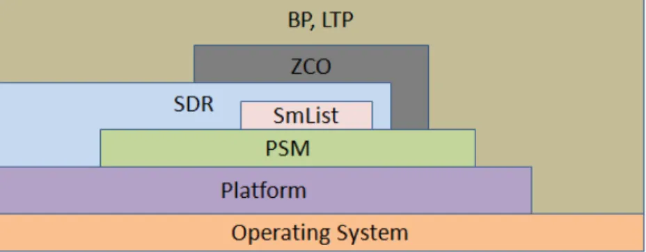
In Table 3.1we summarize the different parts and functions of the ION software in-frastructure built in C programming language and Figure 3.1gives an overview of ION functional dependencies. ION uses a simple header compression scheme to improve trans-mission efficiency called the Compressed Bundle Header Encoding (CBHE) scheme. It is database centric unlike its predecessor DTN2 [31]. The CBHE-conformant BP Endpoint IDs are functionally similar to Internet socket addresses where the element numbers are analogous to IP addresses and service numbers are analogous to TCP and UDP port numbers as for the Internet. Fragmentation and reassembly is well taken care of in the ION infrastruc-ture. To minimize transmission overhead and to accommodate asymmetric links in an IPN,
Figure 3.1: ION Software Functional Dependencies.
ION wants to send downlink data in the largest possible aggregations and termed it as coarse-grained transmission. But again to minimize head-of-line blocking (delay in transmission of a newly presented high-priority item) and data delivery latency by using parallel paths (i.e., to provide fine-grained partial data delivery, and to minimize the impact of unexpected link termination), ION sends downlink data in the smallest possible aggregations and has termed it as fine-grained transmission. ION achieves both these functions at two different layers of the software stack. At the application layer small Application Data Units (ADUs) are generated on the order of 64 Kb which enables fine grained transmission. Lower in the stack at the BP/LTP convergence layer the small bundles which are of similar kind (i.e., same priority level or destined for the same LTP engine) are aggregated into single blocks for delivery. This enables coarse-grained transmission. ION also supports Contact Graph Routing (CGR) which is a dynamic routing scheme used to compute the routes through a
time varying topology of scheduled communication contacts in an IPN. Each node builds a contact graph data structure from the range and contact timeline entries and uses it to make the routing decisions. ION implements the concept of One Way Light Time (OWLT) which is the time taken for an eletromagnetic signal to travel one way between Earth and a spacecraft or some other celestial body. The node architecture and processing within the node has been further elaborated in [5]. Currently the DTNRG is in an effort to establish a worldwide collection of nodes running Bundle Protocol Agents (BPAs) that represent the DTN implementations of DTN2 and the ION [12].
3.2
ORBIT Testbed
Figure 3.2: ORBIT Experiment support architecture.
The ORBIT (Open Access Research Testbed for Next-Generation Wireless Networks) testbed is a flexible wireless network testbed, supported by NSF and located at WINLAB in Rutgers University. It contains an indoor radio grid of 400 nodes arranged in a 20 by 20 matrix. The wireless network itself poses a challenge as its parameters keep varying from time to time. The ORBIT testbed allows to set the various properties and parameters of the wireless network and capture all dependencies and most environmental conditions
Figure 3.3: Execution of an ORBIT experiment from the User’s point of view.
(especially complex radio link layer issues) to facilitate repeatable experiments. It even allows users to remotely control the experiments.
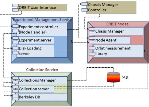
ORBIT may be viewed as a set of services where we can input experimental definitions and receive the experimental results as output as illustrated in Figure3.2. The experimental definition is a Ruby script that interfaces to the ORBIT services. These services can reboot each of the nodes in the 20 by 20 grid, then load an operating system image, any modified system software and application software on each node, and set the relevant parameters for the experiment. Each ORBIT Radio Node is a real PC sitting at WINLAB with a 1 GHz VIA C3 processor, 512 Mb of RAM, 20 GB of local disk, two 100BaseT Ethernet ports, two IEEE 802.11 a/b/g cards and a Chassis Manager to control the node. Figure3.3shows the flow of experiment execution from the user’s point of view and how the user can interact with the testbed. The Nodehandler component functions as an Experiment Controller and
multicasts commands to the nodes at the right time and keeps track of the experiment flow. Nodeagents reside at each node which then executes these commands and also reports back to the Nodehandler. With the help of these two components the user controls the testbed and enables automated collection of experimental results through the ORBIT Measurement Framework & Library (OML) [43]. It uses a SQL database to persistently store and retrieve these results for analysis as and when required.
3.3
Experiment Environment Setup
For experiment setup we choose a group of nodes on the ORBIT testbed. Among them one single node is chosen and tailored to support the DTN architecture. The node runs Linux operating system on which we install the ION software module. The Expat XML parser library written in C language is also required to support ION execution. Once the system is ready to implement the DTN architecture we save the system image on the remote testbed. Later we load the saved image on the other chosen nodes in the group. We need to modify theconfig.rcfile of each node to set up the network topology. For DTN-based space
networks ad-hoc information discovery is costly and it becomes backdated by the time the information is communicated to a second node. It is more effective to pre-place information at the network nodes tagged with the dates and times. This is done in the configuration file by implementing egress plans and contact graphs.
ION can only forward bundles to a neighboring node by queuing them on some explicitly specified outduct. Specifications that associate the neighboring nodes with these outduct comprise the egress plan. Contact graphs on the other hand specify the time duration during which a transmitting and receiving node remains in contact. Each contact is characterized by its start time, its end time, the identities of the transmitting and receiving nodes, and the rate at which data is expected to be transmitted by the transmitting node during the indicated time
period. Finally, we specify a range which is the time period during which the displacement between two communicating nodes is expected to vary by less than 1 light second from a stated anticipated distance. A sample example of the configuration file is shown in Figure
3.4where two nodes communicate with one another using User Datagram Protocol (UDP). The uplink and downlink data rate is specified as 10000 bytes. The contact between the two nodes remains active for a duration of 600 seconds (10 minutes). Implementing these specifications help us to build the network topology. The design of the network is developed from observation of ephemeris data. Table3.4shows the ephemeris data label while Tables
3.2and3.3shows a sample of data subset for Mars Reconnaissance Orbiter (MRO) over a specific period of time. From these informations we can retrieve the position and velocity vectors of a given celestial structure relative to its center of motion and a reference frame.
Table 3.2: Ephemeris data sample for MRO.
‘
STRUCTURE ID CENTER FRAME
MRO HGA OUTER GIMBAL -74213 -74000
MRO SPACECRAFT MRO HGA -74214 -74213
MRO HGA MRO LGA1 -74220 -74213
MRO SPACECRAFT MRO SAPX OUTER GIMBAL -74313 -74000
MRO SAPX MRO SAPX C1 -74315 -74313
MRO SPACECRAFT MRO SAMX -74324 -74323
MRO SAMX MRO SAMX C1 -74325 -74323
Table 3.3: Ephemeris data sample for the different MRO structures.
NAME RELATIVE TO TYPE NAIF
ID Non Built-in Mars
Frames
MRO MME OF DATE rel.to J2000 DYNAMIC -74900 Spacecraft frame MRO SPACECRAFT rel.to MME OF DATE CK -74000 Science Instrument
frames
MRO CRISM BASE rel.to SPACECRAFT FIXED -74011 Antenna frames: MRO HGA BASEPLATE rel.to SPACECRAFT FIXED -74211
Our experiment is based on two simple scenarios of Earth to Moon and Earth to Mars communication which have been elaborated in Chapter 4. Once we set up the network
Figure 3.4: Configuration File for 2 Node Communication using UDP
topologies we run the experiment for a fixed duration of time, execute applications on an ORBIT node through Ruby script files and collect experimental data. A sample example of the Ruby script file is shown in Figure3.5which starts the ION application on 4 nodes at the same time taking the configuration file at each node as input. It helps in creating a wrapper class around the applicationionstart. After the ION application is started we wait
for a few seconds for the nodes and the network to prepare itself for communication. Other ION applications likebpsource,bpsinkandbpsendfileare then used for bundle transmission.
Table 3.4: Ephemeris data label.
PDS VERSION ID = PDS3
RECORD TYPE = FIXED LENGTH
RECORD BYTES = 1024
ˆSPICE KERNEL = ”mro sc psp 101214 101220.bc”
MISSION NAME = ”MARS RECONNAISSANCE ORBITER”
SPACECRAFT NAME = ”MARS RECONNAISSANCE ORBITER”
DATA SET ID = ”MRO-M-SPICE-6-V1.0”
KERNEL TYPE ID = CK
PRODUCT ID = ”mro sc psp 101214 101220.bc”
PRODUCT CREATION TIME = 2012-06-05T20:57:04
PRODUCER ID = ”NAIF/JPL”
MISSION PHASE NAME = ”PRIMARY SCIENCE”
PRODUCT VERSION TYPE = ACTUAL
PLATFORM OR MOUNTING NAME = ”NA”
START TIME = 2010-12-18T12:28:28
STOP TIME = 2010-12-19T12:28:28
SPACECRAFT CLOCK START COUNT = ”2/0860010026.245” SPACECRAFT CLOCK STOP COUNT = ”2/0860025679.058”
TARGET NAME = MARS
INSTRUMENT NAME = ”MRO SPACECRAFT”
NAIF INSTRUMENT ID = -74000
SOURCE PRODUCT ID = ”N/A”
NOTE = ”See comments in the file for details”
OBJECT = SPICE KERNEL
INTERCHANGE FORMAT = BINARY
KERNEL TYPE = POINTING
DESCRIPTION = ”MRO SPICE CK file providing actual telemetry-based orientation of the MRO spacecraft bus for a part of the Primary Science phase of the mission, created by NAIF, JPL. ”
Chapter 4
Experiments and Results
4.1
Introduction
In this chapter, we discuss the problem of setting up a space network in a terrestrial environment and then varying the network parameters to gain an insight into the setup. We design and implement two different network scenarios to study the problem and measure the propagation delay of transmitting a bundle from source to destination. The first scenario implements a network from Earth to Moon and the second scenario is a network from Earth to Mars. We keep alive both the scenarios for a specific duration and transmit bundles from the source to the destination while implementing dynamic change in the topology from time to time.
4.2
Network Scenario
4.2.1
Scenario 1: Lunar Mission
The network scenario is shown in Figure4.1where Node 1 represents the Missions Control Center (MCC) - an entity managing aerospace flight operations from the point of launch
to the end of a mission. It is an Earth based node and all telemetric data is destined for this node after it is received by the DSN stations. Nodes 2 and 3 act as DSN stations at Goldstone and Madrid respectively. Finally, Node 4 represents the Shackelton station on the south pole of Moon. Any information either scientific data or image collected by Node 4 is sent through the DSN stations to Node 1. We consider One Way Light Time (OWLT) from Earth to Moon as 1.28 light seconds which is an average of the OWLTs for Earth to Moon communication at perigree (closest = 360000km) and at apogee (farthest = 405000km). The uplink datarate from Earth to Moon is set as 1 Kbps while the downlink datarate is 128 Kbps. The network remains alive for 10 minutes. The contact graphs over this period are shown in Figure 4.2. For the first 5 minutes the Madrid DSN station is not in sight with the Moon Shackelton station. It is in Line of Sight (LoS) with the Goldstone DSN station. The Earth rotates and after 5 minutes the Goldstone station moves out of LoS while Madrid comes into view. These two contact graph snapshots are fed into all the 4 nodes which gives them the network topology so as to construct the dynamic route which a bundle should take during transmission.
4.2.2
Scenario 2: Mars Mission
This network scenario is shown in Figure 4.3and it consists of 6 nodes. Nodes 1, 2 and 3 are the same as Scenario 1. Node 4 represents a Mars orbiter called Mars Atmosphere and Volatile EvolutioN (MAVEN). It is part of NASAs’ Mars Scout 2013 mission and we included it into our design as a futuristic vision. Node 5 represents the Mars Reconnaissance Orbiter (MRO) which has been launched on August 12, 2005, and attained Martian orbit on March 10, 2006. Finally, Node 6 represents a Mars rover called the ExoMars rover which is an autonomous six-wheeled terrain vehicle planned for a future robotic mission to Mars in search for possible biosignatures of Martian life, past or present. Nodes 2 and
Figure 4.1: Scenario 1 depicting the Earth to Moon communication configuration.
Figure 4.2: Contact graphs for Scenario 1: Lunar Mission.
3 act as the major elements in the network to receive all telemetric signals sent from the Mars orbiters i.e., nodes 4 and 5 and then they are sent to the MCC Node 1. The OWLT for Earth to Mars communication is taken as an average of 324 light seconds. It varies as Mars moves to the farthest and closest to Earth. The OWLT between a Mars orbiter and the Mars surface is taken as 20 light seconds and the communication time between MCC and DSN
stations is a maximum of 1 light second which is the normal terrestrial Internet speed. The communication datarates are as follows:
• Mars rover↔Mars orbiter = 16 Kbps • Earth→Mars = 1 Kbps
• Mars→Earth = 128 Kbps
The network is alive for a duration of 2 hours. Figure4.4shows the contact graphs over this time period. Communication becomes a challenge as both Earth and Mars rotate and bringing the celestial bodies in LoS is difficult. Furthermore the Mars orbiters have their own orbital periods - MAVEN has an orbital period of 4.5 hours and MRO has an orbital period of 35 hours. Keeping these numbers and ephemeris data in mind we design the contact graphs so that within the small time duration of 2 hours each node has a chance to be part of a route for bundle transmission.
4.3
Experimental Results
4.3.1
Verifying Network Operation
In this section, we present the network statistics that help us to understand IPN and its implementation. We run Scenario 1 for a duration of 10 minutes over 2 tests. In the first Test A, 4 bundles are sent from the source Node 4 to the destination Node 1 during the first 5 minutes. After that the network is left idle for the next 5 minutes. In the second Test B, 7 bundles are sent from the source Node 4 to the destination Node 1. In the first 5 minutes we send 2 bundles and in the last 5 minutes we send 5 more bundles. After running the tests the statistics are drawn from both the networks (Earth - Moon, Earth - Mars) and they are shown in Figures4.5and 4.6respectively. The network statistics gives the
Figure 4.3: Scenario 2 depicting the Earth to Mars communication configuration.
bundle transmission route and 8 different types of network activities as shown in Table4.1. The figures verify the contact graphs of the Lunar Mission and the correctness of network operation. We also notice that for Test A the bundle processing at Node 3 is zero while the bundle processing at Node 4 and Node 2 are equal and higher than that required at Node 1. Similarly if we interpret the Figure for Test B, the red border around Node 3 indicates a higher processing requirement among the two intermediate nodes. Resources in space networks are very expensive. Hence we try to gain an insight into what factors lead to the exhaustion of a node. We can clearly see that a balance is needed on the number of bundles sent over alternative routes and it also requires a knowledge of the contact times over a given network. Appropriate load balancing with contact graph knowledge can increase the lifetime of the network. However, there are also other factors that might affect the balance such as spacecraft size, link capacity and asymmetric contact durations at different parts of the network, which we do not look into. In the next section we study the bundle transmission
Figure 4.4: Contact graphs for Scenario 2: Mars Mission.
delay based on Scenario 1 and Scenario 2.
4.3.2
Studying Bundle Transmission Delay
A bundle is transmitted from source to destination over a given route based on contact graph snapshot at that instant of time. In Delay Tolerant Networks a bundle may leave the source for its destination but there might be a disconnection in the middle of the network. In such conditions ION has the provision to store and take custody of the bundle at the local node until a connection is established. In our second scenario we try to study the delay in bundle transmission over a duration of 2 hours during which network partitions are created. The
Table 4.1: Description of different network activities for an ION implementation.
src The measure of the number of bundles for which the local node is the source fwd The number of bundles forwarded from the local node. Re-forwards due to
custody transfer timeouts are also counted
xmt The number of bundles passed to the convergence layer protocol(s) for trans-mission from this node. Re-forwards due to custody transfer timeouts are also counted as retransmissions at the convergence layer
rcv The measure of the number of bundles received by the local node
dlv The number of bundles delivered to applications via endpoints on the local node ctr This message reports on the custody refusal signals received at the local node ctt The number of custodial bundles for which convergence-layer transmission
failed at this node
exp The number of bundles destroyed at this node due to TTL expiration
Figure 4.5: Test A: Network statistics for transmitting 4 bundles.
bundle lifetime or TTL (Time to Live) is set to a value of 600 seconds. A total of 20 bundles are sent over the duration of 2 hours and the bundles to corresponding time slots are shown in Table4.2. Each bundle is sent from the source Node 7 to the destination Node 1. After
Figure 4.6: Test B: Network statistics for transmitting 7 bundles.
Table 4.2: Bundles sent at different time slots (in hours:minutes) for Scenario 2: Mars Mission. 0-10 10-15 15-20 20-30 30-50 50-60 1-1:15 1:15-1:20 1:20-1:30 1:30-1:35 1:35-1:50 1:50-2 B1 B3 B5 B7 B9 B11 B13 B15 B16 B18 B19 B20 B2 B4 B6 B8 B10 B12 B14 B17
running the experiment we show the status of the bundles in the network along with their corresponding counts in Figure4.7. We find that there are a total of 19 bundles that are successfully delivered to the destination. Due to the disconnection of the source node from the network in the last time slot as shown in the contact graph, the 20th bundle remains undelivered. Transmission of a bundle through the DTN can fail mainly due to two reasons
-Figure 4.7: The status of the bundles in the network and their corresponding counts.
contact failure and custody refusal. Situations may arise where a contact between two nodes does not occur for a long time period during which the bundle TTL expires or a bundle cannot be transmitted within the set contact period of the two communicating nodes. For both the cases the bundle is removed from its outbound transmission queue and the Dynamic Route Computation Algorithm is re-applied to the bundle so that an alternate route can be computed. For our experiment bundles which undergo this kind of failure are given a small alphabet version (such as B5a) when its route is recomputed. There are a total of 17 bundles whose route needs to be recomputed. However, a node might also refuse custody of a bundle because it finds it impossible to forward the bundle. Such bundles are simply discarded, but discarding any such bundle that is marked for custody transfer will cause a custody refusal
signal to be returned to the bundles current custodian. Again the bundle route needs to be recomputed.
Figure4.8shows the delay in transmission for each bundle. We perform two tests - Test A and Test B on Scenario 2. All parameters for both the tests are kept same. We get similar results except for a few differences which is accountable to the multiprocessing capability of a node leading to different bundle processing times. However, in both the tests we find that the bundles 11 and 12 take the maximum time to reach the destination. It is almost 1732.3/345.69 = 5.011times the nominal delay for the network. It is a consequence of these two bundles being repeatedly discarded at different times in different parts of the network. Figure 4.9through Figure4.12 demonstrates the delay in bundle transmission
Figure 4.8: Transmission Delay of Bundles through the DTN.
based on a number of different factors. We now use Scenario 1 to study the bundle transmis-sion delay. Two new applications are developed, implementing delay calculation and bulk bundle transmission. They are named assend andrecvfor sending and receiving bundles
respectively and are designed to take the source and destination eids as input. Calculating delay seems to be quite challenging since it requires the whole network to be synchronized. We achieve this by writing a script to synchronize the whole network through ORBIT console. As shown below we subtract the sum of the bundle’s creation time (provided in the BpDelivery structure that gets populated when we call bp receive function in the recv application) and 946684800 value (required to convert from the internal DTN Epoch 2000 time to Unix epoch time), from the current time at the moment bp receive function returns (as provided by the getUTCTime function in the ici library of ION software module). This finally gives us the time taken by a bundle to reach from the source to the destination in seconds.
Bundle transmission time =Current time when bundle is received−(Bundle creation time+
946684800)
In Figure4.9we perform 4 tests - Test A, Test B, Test C and Test D with the same
mental parameters and topology while varying the size of the bundle from 10Kb to 20Mb. We can clearly notice the increase in bundle transmission delay time with increasing bundle size. Henceforth, we always take the average of 4 tests, to obtain a single delay value. This removes the unpredictability due to node multiprocessing that was observed for Test A and Test B in Figure4.8.
In our next experiment we introduce a variation in Scenario 1 topology as depicted in Figure
4.10. An extra node - Node 5 and Node 6 is included in each of the routes, 4-2-1 and 4-3-1 respectively. In another variation we include 2 extra nodes in each route - nodes 5, 7 and nodes 6, 8 respectively. The contact graph routes remain the same as in Scenario 1 over the duration of 10 minutes. The plot in Figure4.11shows the delay in bundle transmission based on bundle size which is varied from 10Kb to 20Mb. It is seen that the bundle transmission delay gradually increases as more number of nodes are added to the topology. An average increase of 43.25% is noticed when we add 1 extra node to the route and about 87.92% when we add 2 extra nodes to the route. This clearly depicts the effect of increasing hops on the delay of bundle transmission. In order to evaluate the impact of the increase in
![Table 1.1: Classification of Space Communication Protocols (Adapted from [42]).](https://thumb-us.123doks.com/thumbv2/123dok_us/10191069.2921860/14.918.242.726.663.994/table-classification-space-communication-protocols-adapted.webp)
![Figure 2.3: The two basic Bundle Protocol block Formats (redrawn from [37]).](https://thumb-us.123doks.com/thumbv2/123dok_us/10191069.2921860/27.918.267.706.164.612/figure-basic-bundle-protocol-block-formats-redrawn.webp)
![Figure 2.5: An example of DTN Implementation Architecture : The architecture shows how a bundle forwarder interacts with the other components and utilizes various protocols for data transmission (adapted from [15]).](https://thumb-us.123doks.com/thumbv2/123dok_us/10191069.2921860/29.918.277.708.161.444/implementation-architecture-architecture-forwarder-interacts-components-protocols-transmission.webp)