NAVAL
POSTGRADUATE
SCHOOL
MONTEREY, CALIFORNIA
THESIS
Approved for public release; distribution is unlimited
AUTOMATING INFORMATION ASSURANCE FOR CYBER SITUATIONAL AWARENESS WITHIN A SMART
CLOUD SYSTEM OF SYSTEMS
by
Kuan Wei Edmund Teo March 2014
Thesis Advisor: Deborah E. Goshorn
REPORT DOCUMENTATION PAGE Form Approved OMB No. 0704-0188
Public reporting burden for this collection of information is estimated to average 1 hour per response, including the time for reviewing instruction, searching existing data sources, gathering and maintaining the data needed, and completing and reviewing the collection of information. Send comments regarding this burden estimate or any other aspect of this collection of information, including suggestions for reducing this burden, to Washington headquarters Services, Directorate for Information Operations and Reports, 1215 Jefferson Davis Highway, Suite 1204, Arlington, VA 22202-4302, and to the Office of Management and Budget, Paperwork Reduction Project (0704-0188) Washington DC 20503.
1. AGENCY USE ONLY (Leave blank) 2. REPORT DATE
March 2014
3. REPORT TYPE AND DATES COVERED
Master’s Thesis
4. TITLE AND SUBTITLE
AUTOMATING INFORMATION ASSURANCE FOR CYBER SITUATIONAL AWARENESS WITHIN A SMART CLOUD SYSTEM OF SYSTEMS
5. FUNDING NUMBERS
6. AUTHOR(S) Kuan Wei Edmund Teo
7. PERFORMING ORGANIZATION NAME(S) AND ADDRESS(ES)
Naval Postgraduate School Monterey, CA 93943-5000
8. PERFORMING ORGANIZATION REPORT NUMBER
9. SPONSORING /MONITORING AGENCY NAME(S) AND ADDRESS(ES)
N/A
10. SPONSORING/MONITORING AGENCY REPORT NUMBER
11. SUPPLEMENTARY NOTES The views expressed in this thesis are those of the author and do not reflect the official policy or position of the Department of Defense or the U.S. Government. IRB Protocol number ____N/A____.
12a. DISTRIBUTION / AVAILABILITY STATEMENT Approved for public release; distribution is unlimited
12b. DISTRIBUTION CODE 13. ABSTRACT (maximum 200 words)
In a world in which data is being generated in increasing large volumes and is easily accessible to multiple users in a cloud environment, there is a need to maintain situational awareness and information assurance of the data, ensuring the data is being monitored for vulnerabilities. This is especially crucial for military operations where the information being used to support the mission is confidential and readily available throughout the mission. It is essential to maintain the integrity of that information. The need is even more critical when data is being used to help save lives in natural disaster situations.
A trio system concept within an enterprise/cloud network is developed in this research to provide situational awareness and command and control abilities to users, for detecting possible cyber attacks on network and computing resources, and maintaining confidentiality, integrity, and availability of critical data within the network.
A systems engineering approach was used to develop and propose the solution to ensure information assurance and cyber situational awareness within a smart cloud of system of systems. This thesis provides system diagrams of the proposed architecture focusing on one of the systems using IDEF0 diagrams, and a feature matrix to demonstrate the concept of Detect, Identify, Predict, and React model. A proof-of-concept experiment for the Identify model is discussed.
14. SUBJECT TERMS Automating Information Assurance, Cyber Situational Awareness, DIPR Model, Smart Cloud System of Systems, Cyber Sensors, Systems Engineering, Data Science
15. NUMBER OF PAGES 161 16. PRICE CODE 17. SECURITY CLASSIFICATION OF REPORT Unclassified 18. SECURITY CLASSIFICATION OF THIS PAGE Unclassified 19. SECURITY CLASSIFICATION OF ABSTRACT Unclassified 20. LIMITATION OF ABSTRACT UU
Approved for public release; distribution is unlimited
AUTOMATING INFORMATION ASSURANCE FOR CYBER SITUATIONAL AWARENESS WITHIN A SMART CLOUD SYSTEM OF SYSTEMS
Kuan Wei Edmund Teo
Senior Engineer, Defence Science and Technology Agency B.Eng., Nanyang Technological University, 2004
Submitted in partial fulfillment of the requirements for the degree of
MASTER OF SCIENCE IN SYSTEMS ENGINEERING
from the
NAVAL POSTGRADUATE SCHOOL March 2014
Author: Kuan Wei Edmund Teo
Approved by: Deborah E. Goshorn Thesis Advisor
Gary W. Parker Co-Advisor
Clifford Whitcomb
ABSTRACT
In a world in which data is being generated in increasing large volumes and is easily accessible to multiple users in a cloud environment, there is a need to maintain situational awareness and information assurance of the data, ensuring the data is being monitored for vulnerabilities. This is especially crucial for military operations where the information being used to support the mission is confidential and readily available throughout the mission. It is essential to maintain the integrity of that information. The need is even more critical when data is being used to help save lives in natural disaster situations.
A trio system concept within an enterprise/cloud network is developed in this research to provide situational awareness and command and control abilities to users, for detecting possible cyber attacks on network and computing resources, and maintaining confidentiality, integrity, and availability of critical data within the network.
A systems engineering approach was used to develop and propose the solution to ensure information assurance and cyber situational awareness within a smart cloud of system of systems. This thesis provides system diagrams of the proposed architecture focusing on one of the systems using IDEF0 diagrams, and a feature matrix to demonstrate the concept of Detect, Identify, Predict, and React model. A proof-of-concept experiment for the Identify model is discussed.
TABLE OF CONTENTS
I. INTRODUCTION...1
A. SMART CLOUD SYSTEM OF SYSTEMS ...1
B. DISCUSSION WITH VADM JAN TIGHE ON CYBER SA APPLIED TO SMART CLOUD SYSTEM OF SYSTEMS ...3
C. ADDITIONAL STAKEHOLDER INPUT ON CYBER SA OF SMART CLOUD SYSTEM OF SYSTEMS ...4
D. HUMANITARIAN ASSISTANCE/DISASTER RELIEF OPERATION ...10
E. CAPABILITY GAP AND PROPOSED CAPABILITY CONCEPT ...11
F. THESIS STRUCTURE ...16
II. BACKGROUND ...17
A. SMART CLOUD SYSTEM OF SYSTEMS ...17
B. DETECT, IDENTIFY, PREDICT, REACT INTELLIGENCE AUTOMATION MODEL ...18
C. SOCIAL MEDIA AND HUMAN ASSISTANCE/DISASTER RELIEF OPERATIONS ...21
D. INFORMATION ASSURANCE ...25
E. CRITICAL SECURITY CONTROLS ...28
F. SYSTEMS ENGINEERING PROCESS...36
III. PROPOSED ARCHITECTURE ...39
A. CYBER SITUATIONAL AWARENESS AND COMMAND AND CONTROL SYSTEM OF SYSTEMS CONCEPT ...39
B. SYSTEM OPERATIONAL USE CASES ...43
C. INTELLIGENCE AUTOMATION APPLIED TO INFORMATION ASSURANCE ...45
D. EXTERNAL SYSTEMS DIAGRAM ...50
E. FUNCTIONS DEFINITION AND DECOMPOSITION ...51
F. IDEF0 DIAGRAM OF PROPOSED SYSTEM ...55
G. REQUIREMENTS ANALYSIS ...70
H. PHYSICAL ARCHITECTURE OF IASA SYSTEM ...87
I. SOFTWARE ARCHITECTURE ...94
J. TRACEABILITY MATRIX OF FUNCTIONAL ALLOCATION ...96
K. PROPOSED INTELLIGENCE AUTOMATION FEATURE MATRIX ...96
L. PROPOSED INTELLIGENCE AUTOMATION CONFIGURATION FILE ...100
IV. PROOF OF CONCEPT OF THE SYSTEM ...105
A. SCOPE AND EXPERIMENT DESIGN ...105
V. CONCLUSIONS, RECOMMENDATIONS, AND AREAS FOR FURTHER
RESEARCH ...119
A. CONCLUSIONS ...119
B. RECOMMENDATIONS TO IMPROVE THE PROOF OF CONCEPT ...120
C. AREAS FOR FURTHER RESEARCH ...120
APPENDIX A. DETECT FEATURE MATRIX ...123
APPENDIX B. IDENTIFY DIPR MODEL MATLAB CODE ...127
APPENDIX C. IDENTIFY WRITE XML MATLAB CODE ...133
LIST OF REFERENCES ...135
LIST OF FIGURES
Figure 1. Smart cloud system of systems (after Goshorn 2013). ...2
Figure 2. VADM Tighe discusses the need for cyber situational awareness within Smart Cloud System of Systems at the Distributed-GIG Intelligence Automation Systems (DGIAS) Lab for Military and Homeland Security (author in far right of picture) (from Ammon 2013). ...3
Figure 3. Mr. Al Miller (third from left) from USD(P) discusses the need for interoperable alerts within a smart cloud system of systems (author on far left.) ...5
Figure 4. Mr. Richard Marchant (far right) from OUSD (AT&L) discusses the need to perform test and evaluation of new capabilities (author second from right). ...6
Figure 5. Research with the Office of Naval Research applies the Detect-Identify-Predict-React (DIPR) intelligence automation framework to cyber situational awareness within a smart cloud system of systems (Goshorn 2013). ...8
Figure 6. Defence Minister Dr. Ng Eng Hen announces the new Cyber Defence Operations Hub on June 29, 2013 (Lim 2013). ...9
Figure 7. Israel Aerospace Industries (IAI) cyber research and development center in Singapore (Jewish Business News 2014). ...9
Figure 8. Application of smart cloud SoS during a humanitarian assistance and disaster relief operation (after Goshorn 2013). ...11
Figure 9. Concept diagram for cyber situational awareness of a smart cloud system of systems. The cyber SA system of systems utilizes two parallel DIPR intelligence automation systems (one passive cyber defense and one active cyber defense) that both interact with each other and also independently provide cyber alerts to the overarching cyber SA system...14
Figure 10. Smart cloud system of systems (after Goshorn 2013). ...18
Figure 11. Concept of DIPR model and its subsystem (after Goshorn 2011). ...19
Figure 12. XML document example (from w3schools 2014). ...21
Figure 13. Twitter sample payload, JSON format (from GitHub 2014). ...24
Figure 14. The three states of data are “data in use,” “data at rest,” and “data in motion” (from Ball 2013). ...26
Figure 15. Control 1 system entity relationship diagram (from SANS n.d.). ...29
Figure 16. Control 3 system entity relationship diagram (from SANS Institute 2014). ...30
Figure 17. Control 10 system entity relationship diagram (from SANS Institute 2014). ...31
Figure 18. Control 11 system entity relationship diagram (from SANS Institute 2014). ...32
Figure 19. Control 13 system entity relationship diagram (from SANS Institute 2014). ...33 Figure 20. Control 14 system entity relationship diagram (from SANS Institute
Figure 21. Control 17 system entity relationship diagram (from SANS Institute). ...35
Figure 22. Control 19 system entity relationship diagram (from SANS Institute). ...36
Figure 23. Systems engineering “Vee” model (from Buede 2009, p. 10). ...37
Figure 24. Focus on IASA in the cyber situational awareness system of systems of specified information in the cloud (boxed in red). ...40
Figure 25. Typical result of the DIR command in MATLAB. ...47
Figure 26. Typical result of the FILEATTRIB command in MATLAB. ...48
Figure 27. Output display of Process Explorer. ...49
Figure 28. External system diagram for the system. ...50
Figure 29. Functional hierarchy of the system. ...52
Figure 30. Functional hierarchy of the function “Sense Information Data Environment.” ...54
Figure 31. Functional hierarchy of the function “Provide Intelligence Automatize Framework for IASA.” ...54
Figure 32. Level 1 IDEF0 diagram of the system. ...55
Figure 33. Level 2 IDEF0 diagram of the function “Provide Information Assurance SA.” ...57
Figure 34. Level 3 IDEF0 diagram of function “Sense Information Data Environment.” ...59
Figure 35. Level 4 IDEF0 diagram of function “Sense Stored/Transit/In Use Information.” ...61
Figure 36. Level 3 IDEF0 diagram of function “Provide Intelligence Automatize Framework for IASA.” ...63
Figure 37. Level 4 IDEF0 diagram of function “Detect.” ...65
Figure 38. Level 5 IDEF0 diagram of function “Detect Stored/Transit/In Use Data.” ...66
Figure 39. Level 4 IDEF0 diagram of function “Identify.”...68
Figure 40. Focus on IASA in the cyber situational awareness system of systems of specified information in the cloud. ...88
Figure 41. Physical Architecture of IASA with “Detect” function retained with IASA...89
Figure 42. Physical Architecture of IASA with “Detect” function deployed at smart mini cloud SoS. ...90
Figure 43. IASA receiving configuration files from C2 and filtering down to sub-systems. ...91
Figure 44. Data sensor monitoring targets’ information. ...92
Figure 45. Detect processing sensor data and updating feature matrix. ...93
Figure 46. Identify, predict, and react software analyzing and reacting to the collected data. ...94
Figure 47. Software architecture of IASA ...95
Figure 48. Overview of feature matrix XML schema. ...97
Figure 49. “Detect” XML schema. ...99
Figure 50. “Identify” XML schema ...100
Figure 51. Sense configuration XML schema. ...101
Figure 55. XML file from the detection software for a normal case. ...107
Figure 56. XML file from the detection software for loss of confidentiality. ...108
Figure 57. XML file from the detection software for loss of integrity. ...109
Figure 58. XML file from the detection software for loss of availability. ...110
Figure 59. MATLAB coding for Identify, extracting data from XML and assigning variables to the data. ...112
Figure 60. MATLAB coding for Identify, comparing the data extracted from detect XML. ...113
Figure 61. MATLAB coding for Identify XML Write. ...114
Figure 62. XML output from Identify module for normal case. ...115
Figure 63. XML output from Identify module for loss of confidentiality case...115
Figure 64. XML output from Identify module for loss of integrity case. ...116
LIST OF TABLES
Table 1. Nine combinations of information assurance at different states of data. ...46 Table 2. Traceability matrix of the IASA system. ...96
LIST OF ACRONYMS AND ABBREVIATIONS
API Application Programming Interface
C2 Command and Control
CADSA Cyber Attack Detection Situational Assurance
CCE Common Configuration Enumeration
CPE Common Platform Enumeration
CSAC2 Cyber Situational Awareness and Command and Control
CTO Chief Technology Officer
DCO DoD Cyber Operations
DGO DoDIN Global Operations (formerly DoD GIG Operations) DIPR Detect, Identify, Predict and React
DLP Data Loss Prevention
DoD Department of Defense
DoDIN DoD Information Network
EMMI Energy, Material, Material Wealth, and Information
GIG Global Information Grid
HADR Humanitarian Assistance and Disaster Relief
HTML HyperText Markup Language
IA Information Assurance
IAI Israel Aerospace Industries
IASA Information Assurance Situational Awareness
IDEF0 Integrated Computer Aided Manufacturing (Icam) DEFinition for Function Modeling
IP Internet Protocol
IPR Identify, Predict and React IPS Intrusion Prevention System IPsec Internet Protocol Security
ISR Intelligence Surveillance and Reconnaissance
IW Information Warfare
JSON JavaScript Object Notation
KML Keyhole Markup Language
LAN local area network
MAC media access control
MS Microsoft
NAC network access control
NORAD North American Aerospace Defense Command
NPS Naval Postgraduate School
OPNAV Office of Chief of Naval Operations
ONR Office of Naval Research
OUSD (AT&L) Office of the Under Secretary of Defense, Acquisition, Technology, & Logistics
OUSD (P) Office of the Under Secretary of Defense, Policy
RAM random access memory
REST Representational State Transfer
RSS rich site summary
SA situational awareness
SAF Singapore Armed Forces
SoS system of systems
SSL secure sockets layer
S&T Science and Technology
SYN synchronize
TCP transmission control protocol TLS transport layer security
USN United States Navy
USNORTHCOM United States Northern Command
VADM Vice Admiral
VPN virtual private network
XCCDF eXtensible Configuration Checklist Description Format
EXECUTIVE SUMMARY
A new realm of threat has emerged with the dawn of cyber warfare; data is being generated in increasingly huge amounts, making the management and monitoring of data difficult. Cyber attack methodology has also become more sophisticated. Ensuring data has not been compromised and maintaining its confidentiality, integrity, and availability is crucial for military operations, especially when data is being used to save lives in humanitarian assistance and natural disaster relief operations. This thesis proposes a system of systems engineering methodology for integrating and configuring an intelligence automation system for the purpose of enabling cyber command and control and cyber situational awareness.
A trio of intelligence automation systems, namely Cyber Situation Awareness and Command and Control (CSAC2), Cyber Attack Detection Situation Awareness (CADSA), and Information Assurance Situation Awareness (IASA), was proposed to achieve the purpose of providing automated information assurance for cyber situation awareness of data, including the assurance of data confidentiality, integrity, and availability. A proof of concept using the Identify software of the Detect, Identify, Predict, and React (DIPR) model of the IASA system was used to automate the information assurance of a target file, which is in the data at rest state, against four test cases. The four test cases are normal operation, loss of confidentiality, loss of integrity and loss of availability of a monitored target of interest. The proof of concept successfully analyzed and updated the feature matrix produced by the Detect software of DIPR model for each of the four test scenarios. Further research can be done to improve the usage of other file characteristics, such as monitoring candidates, studying the effectiveness of monitoring data in other data states, and expanding experimental testing by integrating CSAC2 and CADSA into the test.
A systems engineering approach was used to explore the possible solution to the problem statement focusing mainly on the IASA system. A systematic analysis of the requirements to automate information assurance in the areas of data confidentiality,
systems was performed. After going through the systems engineering process and generating an architecture with an analysis of alternatives, this thesis implements and describes an instantiated proof-of-concept system of a portion of the IASA system, with documented test and evaluation results.
Making use of the Detect, Identify, Predict, and React (DIPR) model, the IASA system is able to perform the task of ensuring information assurance by monitoring, analyzing, and comparing the file characteristics, such as the timestamp and file size of the monitored target. This thesis focused on data in the state of at rest/stored, but the concept can be expanded to other data states such as in transit or in use by applying different types of cyber sensors. The concept can be further expanded with the implementation of CSAC2 and CADSA systems in the network, thereby providing synergy between the applications and producing a robust setup. This trio system of systems will automate generation of alerts to operators and activate cyber controls to close ports or encrypt files in the event of cyber attacks or degradation in information assurance.
ACKNOWLEDGMENTS
I would like to express the deepest appreciation to my advisors, Dr. Deborah E. Goshorn, for her unwavering guidance, and Mr. Gary W. Parker, for his relentless support for this thesis. Without their valuable feedback and persistent help this thesis would not have been possible. Both experts have offered me a valuable lesson in the field of cyber security and information assurance in cloud environment.
I would also like to thank those who have helped me in one way or another during my preparation of this thesis.
Last, but not least, I am thankful to and fortunate enough to get constant support, love, and encouragement from my wife, Karen Chen, who helped to manage the house and kids so well during my course of study in NPS; she is also my source for delicious food. I am thankful also to my beloved beautiful kids, Jazzelle and Jareth, for bringing their laughter and joy into my life.
I.
INTRODUCTION
As an introduction to this thesis, this chapter first explains the reason for selecting this thesis topic, which is derived from both a project on Smart Cloud System of Systems and direct discussions of the cybersecurity issues on Smart Cloud System of Systems with Vice Admiral (VADM) Jan Tighe, currently Commander of 10th Fleet Cyber Command. This chapter then reviews additional stakeholder input for selecting the operational scenario for this thesis application. This chapter then presents the resulting proposed concept of the thesis and the capability gap that the concept fills. Finally, this chapter concludes with a high-level overview of the thesis organization.
A. SMART CLOUD SYSTEM OF SYSTEMS
As part of the Systems Engineering curriculum at Naval Postgraduate School (NPS), a project-based, three-course sequence is required that covers Engineering Systems Conceptualization, Engineering Systems Design, and Engineering Systems Implementation & Operation (Goshorn 2013). There were several projects to choose from, and the author chose to work with the Smart Cloud System of Systems (SoS) with Dr. Deborah Goshorn. This is based on over fifteen years of research on intelligence automation and network-centric system of systems (Goshorn 2010). Figure 1 depicts the Smart Cloud System of Systems model used for representing a network-centric system of systems. The Smart Cloud SoS is made up of a major cloud node and several “mini cloud” nodes. The “mini clouds” represent nodes at tactical sites or at sites in which an operator and/or analyst is using data from the cloud to make a decision. The main cloud node represents a set of enterprise cloud nodes that perform further analysis of the data and is in charge of routing the right data to the right operator/analyst.
Figure 1. Smart cloud system of systems (after Goshorn 2013).
In terms of mini-clouds, there are two kinds: smart sensor mini clouds, and command and control mini clouds. The smart sensor mini clouds collect and analyze data from sensors in multiple domains, such as social media and the physical domain, creating sensor feed data from the Intelligence Surveillance and Reconnaissance (ISR) systems. In addition to the raw data feed (e.g., video feed or social media feed), these mini-clouds also perform a first-pass level of automation and provide output in a standardized alert data file format to the main cloud. The main cloud further fuses the data alerts using automation software, stores the data on the main cloud, and finally distributes the right data to the right user.
Finally, the command and control “mini clouds” serve as the hubs to gather input from the operators and analysts, and also to provide situational awareness (SA) in the form of alerts. The operators input and configure the entire smart cloud system of systems based on what types of situational awareness alerts they want to receive (Goshorn 2013).
B. DISCUSSION WITH VADM JAN TIGHE ON CYBER SA APPLIED TO SMART CLOUD SYSTEM OF SYSTEMS
Figure 2. VADM Tighe discusses the need for cyber situational awareness within Smart Cloud System of Systems at the Distributed-GIG Intelligence Automation Systems (DGIAS) Lab for Military and Homeland Security (author in far right of picture) (from Ammon 2013).
As a member of the Smart Cloud System of Systems project, it was an honor to receive direct stakeholder input from our NPS Interim President, VADM Jan Tighe, who was also acting as director, Decision Superiority OPNAV N2N6F4 at the time, and is now currently serving as Commander, Fleet Cyber Command/Commander, 10th Fleet. During this guest lecture, VADM Tighe discussed information dominance and information warfare (IW) and shared her experiences as a senior IW officer.
In this discussion, the need for capturing information assurance of data within the smart cloud system of systems was relayed by VADM Tighe. As further discussed with the primary advisor of this thesis, this means it is important to monitor the information
moves throughout the smart cloud system of systems. More background on information assurance is provided in Chapter II.
After hearing the importance of being able to monitor information assurance within a cloud environment, and realizing all of the important systems connected to the cloud that could end up with fatal ramifications if the information is not assured, the author developed this concept for solving information assurance behavior analysis based on this need and the existing intelligence automation capabilities from prior research (Goshorn 2010).
As an outcome of this lecture and discussion, this thesis and one other were conceived, as documented in an article published by NPS (Ammon 2013).
C. ADDITIONAL STAKEHOLDER INPUT ON CYBER SA OF SMART
CLOUD SYSTEM OF SYSTEMS
This section discusses the stakeholder input received by the author both directly and indirectly, which directed this thesis topic. By participating in the Smart Cloud System of Systems project, the author had access to discussions with several stakeholders (Goshorn, 2013). Direct input from U.S. Navy (USN) stakeholders included Vice Admiral (VADM) Jan Tighe, U.S. Navy, along with the Chief Technology Officer (CTO) of United States Northern Command/North American Aerospace Defense Command (USNORTHCOM/NORAD) Science & Technology (S&T) office. Indirect input was derived from the Office of Naval Research (ONR) along with stakeholders within Singapore, such as the Singapore Armed Forces.
1. USN Stakeholder Input
As discussed in the previous section, the need for providing information assurance of data within a cloud environment was discussed by VADM Tighe. This discussion is what sparked the development of the capability architected in this thesis.
NORTHCOM/ S&T Office, discussed operational scenarios that are of importance to him. In this discussion, he relayed the need to be prepared for cyber attacks on the smart cloud system of systems (SoS) when the SoS is deployed in a tactical environment for the purpose of supporting a Human Assistance/Disaster Relief (HA/DR) operation. More specifically, understanding the validity and integrity of the data alerts that are sent to the decision maker at the Command and Control “mini cloud” was of upmost interest.
This discussion not only confirmed the need to have information assurance of data to ensure its confidentiality, integrity, and availability, it also scoped which operational scenario the thesis should use: the HA/DR scenario.
3. Office of Under Secretary of Defense, Policy Stakeholder Input
As part of the smart cloud system of systems project, access to additional stakeholders at the Joint Field Experimentation (JIFX) was made available.
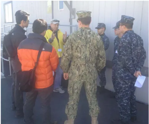
Figure 3. Mr. Al Miller (third from left) from USD(P) discusses the need for interoperable alerts within a smart cloud system of systems (author on
For example, as captured in Figure 3, the Science and Engineering Advisor, Mr. Al Moore, for Policy Integration from the Office of Secretary of Defense, Policy (OUSD(P)), discussed the importance of generating alerts that are interoperable within the smart cloud system of systems.
This requirement was taken into consideration as this thesis concept system does output its alerts using an interoperable standard, as discussed in Section B of Chapter II.
4. Office of Under Secretary of Defense, Acquisition, Technology, and Logistics Stakeholder Input
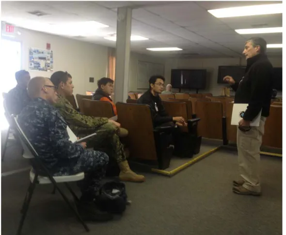
As part of the smart cloud system of systems project, access to additional stakeholders at the JIFX was made available.
Figure 4. Mr. Richard Marchant (far right) from OUSD (AT&L) discusses the need to perform test and evaluation of new capabilities (author second
For example, as captured in Figure 4, Mr. Richard Marchant from the Office of Under Secretary of Defense, Acquisition, Technology, and Logistics (OUSD (AT&L)) discusses the need for performing test and evaluation of new capabilities that trace to requirements.
This thesis includes a traceability matrix in Chapter III that maps the proposed system’s capability to originating requirements. In addition, this thesis provides a preliminary test and evaluation of the capability’s proof-of-concept.
5. Office of Naval Research Stakeholder Input
In SE3201 Engineering Systems Conceptualization course, the primary advisor, Dr. Goshorn presented the need for an intelligence automation infrastructure within the smart cloud system of systems. This infrastructure uses the Detect-Identify-Predict-React (DIPR) model that is described in previous work and is reviewed in Chapter II (Goshorn 2010).
Additionally, the cyber application of this DIPR intelligence automation framework is considered under current research for Office of Naval Research for Code 30, ISR Thrust Program Manager. In this case, stakeholder input is received indirectly from the advisor’s research with the Office of Naval Research for a framework where learning can be achieved based on cyber sensor deployment on the smart cloud system of systems. Figure 5 explains the big picture setup of using DIPR to automate cyber situational awareness of smart cloud system of systems, called “blue team” cyber behavior intelligence automation. “Red team” cyber behavior intelligence automation refers to automating when and how someone should perform a cyber attack on the smart cloud system of systems. Further background on how to apply the DIPR Intelligence automation framework to do this from a blue team perspective performing active cyber defense is found in previous research (Jurjonas 2012). Background on applying cyber intelligence automation from a red team perspective is provided in other research in addition to this thesis (Deptula 2013).
Figure 5. Research with the Office of Naval Research applies the Detect-Identify-Predict-React (DIPR) intelligence automation framework to
cyber situational awareness within a smart cloud system of systems (Goshorn 2013).
6. Singapore Armed Forces and Other Singaporean Stakeholder Input
Finally, as part of this stakeholder analysis review, a preliminary research review on potential stakeholder within Singapore was conducted. From this research, the most significant stakeholder determined was the Singapore Armed Forces and their new Cyber Defence Operations Hub. On June 29, 2013, Defence Minister Dr. Ng Eng Hen (Figure 6) announced the setting up of the hub in order to “fight increasingly prevalent cyber attacks” (Lim 2013). Thus, the need for cyber SA is prevalent within Singapore’s military.
Figure 6. Defence Minister Dr. Ng Eng Hen announces the new Cyber Defence Operations Hub on June 29, 2013 (Lim 2013).
Additional Singaporean stakeholders include research and development organizations such as Israel Aerospace Industries (IAI), who launched a cyber research and development center in Singapore, in cooperation with Singapore’s Economic Development Board (The Jerusalem Post 2014). A photograph supporting the launch of the Singapore IAI R&D Center is captured in Figure 7.
Figure 7. Israel Aerospace Industries (IAI) cyber research and development center in Singapore (Jewish Business News 2014).
D. HUMANITARIAN ASSISTANCE/DISASTER RELIEF OPERATION
A humanitarian assistance/disaster relief (HA/DR) operation was the scenario selected by various stakeholders for the smart cloud system of systems project. HA/DR operations support the nation or region under a disaster in order to minimize deaths and suffering in the affected public. Also, HA/DR operations are supposed to help improve security and stability in the region after a disaster. Finally, HA/DR operations help transition the region to prepare for long-term recovery. Example activities that occur during an HA/DR operation include providing technical aid to the region, building disaster relief warehouses, maintaining emergency operation centers, building shelters and potentially building fire stations. Finally, during these operations, essentials such as food, water, and medication are delivered and distributed throughout the region hit by the disaster (USSOUTHCOM 2014).
Figure 8 depicts how the smart cloud system of systems can be deployed in a HADR scenario for the purpose of detecting terrorist attacks in an area where there are multiple crowds forming. This project assumed there is an operation going on where there are both social media sensors and camera sensors (on both unmanned aerial vehicle (UAV) platforms and tower-based ground platforms) that are performing surveillance of an area where aid is being provided to the masses of people.
Figure 8. Application of smart cloud SoS during a humanitarian assistance and disaster relief operation (after Goshorn 2013).
From stakeholder opinion, there is concern that there are terrorist attacks in the area (both cyber and physical). For the smart cloud system of systems project, an architecture was put together detecting physical attacks in the area of the HA/DR operation.
For this thesis, a capability and architecture is proposed for how to detect cyber terrorist attacks within the smart cloud system of systems that is being used to perform surveillance for physical terrorist attacks.
E. CAPABILITY GAP AND PROPOSED CAPABILITY CONCEPT
This section first describes the capability gap of need for cyber situational awareness within a smart cloud system of systems, which this thesis addresses and is based on stakeholder input. This section then concludes by describing the concept of the proposed capability to fill the capability gap; that is, a cyber situational awareness system
1. Capability Gap
Whether it is a system used in real time during a mission or it is a system being assessed for vulnerabilities prior to being deployed, automation of cyber situational awareness (specifically information assurance) of any system supporting military operations is crucial. Operators in any mission need assurance that the data being used to support that mission is confidential, maintains its integrity, and is available throughout the mission. Additionally, before any system is deployed, such information assurance of that system needs to be categorized by the DoD in order to authorize its deployment (Young 2011; Onuskanich 2011).
Maintaining situational awareness of the data is even more crucial in a cloud environment where data is accessible to multiple users. Because data is more widely available to more users, it is well known that many governments are creating specific measures for how to assess information assurance in such cloud frameworks. One example of these measures is the United States’ FedRamp organization (GSA 2014). Additionally, in cloud environments, the amount of data that needs to be monitored for vulnerabilities is overwhelming. There are not enough analysts to manually handle the data that are collected from such monitoring systems of a cloud framework (Hamel 2013). Thus, a systems approach to automate cyber situational awareness of data and systems within cloud systems and to augment analysts’ work is needed.
Finally, in applications where the data collected will help save lives, as in natural disaster situations, it is important to ensure the data being collected has not been tampered with, but that it maintains its integrity (IDA 2013).
To fill these needs, this thesis chooses to apply an automated cyber situational awareness system to monitor social media data collected in a smart cloud system of systems. This will demonstrate an example of one type of data that needs to be monitored and for which its information confidentiality, integrity, and availability must be assured.
2. Proposed Concept
The proposed solution should provide the user with cyber situational awareness and command and control ability. There are two types of cyber defense: passive and active defense. The proposed solution should exploit these defenses and provide the ability to reinforce each other. This thesis will look at providing a high-level concept cyber situational awareness system of systems (SoS) with the ability to both passively monitor data and devices within a network, such as a smart cloud SoS, as well as actively monitor the network and devices within a smart cloud SoS.
Specifically, the concept will focus on passive defense to provide information assurance of data vulnerability within the smart cloud SoS by providing information assurance alerts with the usage of automating tools. Data collected within a smart cloud SoS vary from warfighting platforms such as weapon systems and sensor systems, and from main cloud stems. The potential loss of confidentiality, integrity, and availability of such data must be avoided, and thus there is a need to automate cyber situational awareness in a smart cloud SoS.
This thesis proposes a system of systems engineering methodology for integrating and configuring an intelligence automation system for the purpose of enabling cyber command and control (C2) and cyber situational awareness (SA). This methodology includes performing the systems engineering process on the overarching SoS with the main focus on just one of the supporting systems. In particular, this thesis first proposes an overarching cyber defense system of systems architecture demonstrating how systems work independently and together for enabling command and control and providing cyber situational awareness. It is first made up of the overarching Cyber SA and C2 (CSAC2) system, followed by two defense systems that are performing intelligence automation via the Detect-Identify-Predict-React framework (Figure 9). The two cyber defense systems are the Cyber Attack Detection SA (CADSA) system, which performs active cyber defense operations, and the Information Assurance (IA) SA (IASA) system, which performs passive cyber defense operations. This thesis documents the high-level system of systems architecture while focusing on the progress of the systems engineering process
Figure 9. Concept diagram for cyber situational awareness of a smart cloud system of systems. The cyber SA system of systems utilizes two parallel DIPR intelligence automation systems (one passive cyber defense and one active cyber defense) that both interact with each other
and also independently provide cyber alerts to the overarching cyber SA system.
Thus, in this thesis, the systems engineering process is applied to the IASA system, which applies DIPR to perform passive cyber defense. After going through the systems engineering process and generating an architecture with an analysis of alternatives, this thesis implements and describes an instantiated proof-of-concept system of a portion of the IASA system, with documented test and evaluation results.
The initial conceptual requirements of this system of systems are documented as needing to be capable of (1) monitoring information assurance of information within specified systems in a cloud framework, along with (2) monitoring for specific cyber attacks on a specified system, (3) alerting information of interest to an operator, and finally (4) allowing the end user to perform command and control over his or her cyber assets.
3. Thesis Research Questions
In order to determine the apt solution for the IASA system, this section presents the primary and subsidiary research questions investigated during the thesis research for proposing a solution to the proposed concept.
Primary Research Question: How does one apply system of systems engineering to create an architecture for automating cyber situational awareness of specified information within a smart cloud system of systems?
Subsidiary Research Questions:
1. What functions would an automated cyber situational awareness system perform, in particular, one that automates information assurance of specified data?
2. How does one model and monitor cyber behaviors of specified information on a system?
3. What are the approaches to automate detecting and tracking degradation of information assurance (i.e., degradation of information confidentiality, integrity, and availability)?
4. What are the cyber sensors needed to capture data sufficient enough to automatically detect and track degradation of information assurance?
F. THESIS STRUCTURE
The need for automating information assurance for cyber situational awareness within the smart cloud system of systems was discussed in this chapter, followed by the proposed overall architecture of the systems. A general background and literature search on the controls to ensure confidentiality, integrity, and availability of data is described in Chapter II. In Chapter III, the detailed system diagrams of the proposed architecture are discussed with a focus on the IASA system using IDEF0 diagrams. The feature matrix used to demonstrate the concept of the Detect, Identify, Predict and React (DIPR) model for the IASA system is also mentioned. In Chapter IV, the proof of concept for the Detect and Identify of the DIPR model is demonstrated and the physical architecture of IASA is discussed. Finally, conclusions, recommended improvements to the proof of concept, and future research work are provided in Chapter V.
II.
BACKGROUND
In addition to background on the systems engineering process used in this thesis, this chapter provides a brief overview of the three technologies used in this thesis, as well as background on the operational scenario selected for this thesis. The three technologies used are the smart cloud system of systems, Detect-Identify-Predict-React (DIPR), and information assurance. The operational scenario and assumptions in question are reviewed, followed by the brief overview of the systems engineering process used in this thesis.
A. SMART CLOUD SYSTEM OF SYSTEMS
1. Smart Cloud System of Systems
The smart cloud SoS is the assumed external system whose data needs are monitored for the cyber situational awareness system of systems. This infrastructure is made up of smart sensor mini clouds, a command and control mini cloud, and the main cloud, as shown in Figure 10. The command and control “mini clouds” represent nodes at tactical sites or at sites in which an operator and/or analyst is using data from the cloud to make a decision. The main cloud node represents a set of enterprise cloud nodes that perform further analysis of the data and is in charge of routing the right data to the right operator/analyst. The smart sensor mini cloud senses a particular domain, such as the physical domain, cyber domain, or social media domain, in order to generate raw sensor data that captures each domain at a certain time.
Figure 10. Smart cloud system of systems (after Goshorn 2013).
In other words, the smart sensor mini clouds collect and analyze data from social media and video feed data from the Intelligence Surveillance and Reconnaissance (ISR) system, and provide output in a standardized alert data file format to the main cloud. The main cloud further fuses these data, distributes it, and stores the data on the main cloud. The command and control mini cloud serves as the hub to gather input from the operators and also to provide cyber situational awareness in the form of alerts. It is important to monitor the IA of the data in its different states of data at rest, in transit, and in use within the smart cloud system of systems.
B. DETECT, IDENTIFY, PREDICT, REACT INTELLIGENCE
AUTOMATION MODEL
The intelligence automation model, Detect-Identify-Predict-React, or DIPR, has been used primarily in sensor-based networks to generate usable, intelligent feedback from raw data provided by conventional sensors such as cameras (Goshorn 2011). It has been used also for automating dynamic defensive cyber operations, which focused primarily on the cyber sensors and detection portions (Jurjonas 2012; Deptula 2013).
Figure 11. Concept of DIPR model and its subsystem (after Goshorn 2011).
In addition to the sensor systems, there are four intelligence automation systems that further process the sensor data, providing alerts that are increasing in complexity at each output of each system. Therefore the alerts that are output from Reaction are the most complex where the sensor data is the lowest level of information, in terms of complexity.
This section briefly discusses each DIPR subsystem: Detect, Identify, Predict, and React.
1. Detect System
Sensors deployed in smart sensor mini clouds provide raw data for processing by a system/processor running the Detect programs. The raw sensor data is analyzed by the Detect subsystem, which creates the detect classifications in the data feature matrix. Features are a low-level classification created from raw data and are describing an object of interest (Goshorn 2011).
2. Identify System
The Identify subsystem processes the Detect features, recognizes when multiple features or conditions have occurred simultaneously, and fuses the data together, generating an intelligent state to which that data belongs. Rules to implement the recognition must be developed and input into the program to determine what feature conditions are required. Ideally, it would be an adaptable learning system that could tailor itself over time (Goshorn 2011).
3. Predict System
At each time interval, the intelligent states generated by the Identify subsystem are then input into the Predict subsystem. These states are then processed by a generalized high-level classifier that recognizes spatiotemporal patterns of states. The input states that also include geo-locations and time of events associated with each state form object sequences, or behaviors. They are then classified as “normal” behaviors, “abnormal” behaviors, and “unclassified” behaviors, based on predefined or learned patterns. These behaviors are then used to predict the future state of the information under observation and output to the React subsystem (Goshorn 2011).
4. React System
The React subsystem provides an appropriate action (control signal and/or alert) based on these predefined rules of engagement associated with each predicted behavior (Goshorn 2011). For example, a control signal to close network ports or encrypt files or folders may be issued as a form of reaction to predict behaviors.
5. Extensible Markup Language (XML) Interoperable File Standard for the DIPR Alerts
Each object that is detected in the Detect stage within DIPR has its own feature space matrix, which is a data structure that stores all the values of the object features that were detected. There are several methods to implement the feature space matrix. One common method is to use the Extensible Markup Language (XML) file standard (w3school 2014).
XML is a structured language, such as HyperText Markup Language (HTML), which was created to structure, transport, and store data. The structure of how data is organized in the document is customized by whoever is creating the XML files (w3school 2014). Figure 12 shows a sample of an XML document.
Figure 12. XML document example (from w3schools 2014).
The XML standard is well suited for DIPR application to the cyber field. In Chapter III, more specific details of the adaptation are described to show how the subsystems and functions work to provide automated information assurance and situational awareness for a smart cloud system of systems.
C. SOCIAL MEDIA AND HUMAN ASSISTANCE/DISASTER RELIEF
OPERATIONS
Recall from Chapter I that the operational scenario selected describes the deploying of a cyber situational awareness system of systems to monitor for cyber attacks against the smart cloud system of systems that is monitoring for physical terrorist attacks in a region in Singapore that had hypothetically been hit with a natural disaster, all as a part of an HA/DR operation.
This scenario also assumes that social media is used by people affected by the disaster during the HA/DR operations. Additionally, this selected HA/DR scenario of a smart cloud system of systems within Singapore assumes that social media is used in Singapore, since one of the smart sensor mini clouds is a social media smart sensor mini cloud that could sense all publicly available social media generated within Singapore.
To ensure that this deployment of a smart cloud system of systems is valid, and that its data is being generated, would require situational awareness of its information assurance; this section describes both the background on the social media usage within Singapore as well as the background on social media usage during HA/DR operations.
Finally, to provide background on what sample social media looks like, this section finishes with a brief example of what Twitter “raw sensor data” looks like. For
this thesis, this is the type of data for which information assurance would be monitored during an HA/DR scenario.
1. Social Media in Singapore
According to a report by Rock Publicity in 2012, social media is heavily adopted in Singapore. In particular, 68.1% of the total population of 3,530,100 in 2012 regularly interacted with social media on their devices at home or anywhere on their mobile devices (Rock Publicity 2012).
With respect to which social media applications are used, most Singaporeans have accounts with multiple social media sites. In fact, Singaporeans are some of the heaviest mobile users on average in Asia, and use social media on mobile devices more than 96% of the rest of the world. Interestingly, they also buy more tablet devices per capita than all of the other Asian nations, appearing to lead the Asian region with respect to the most social media used on these devices. Additionally, almost half of the country’s total population is reported to have a Twitter account, which is higher than the world average. In terms of which city in the world uses Twitter the most, Singapore is reported to be ranked eleventh. In particular, it is reported that the average Singaporean Twitter user tweets more than twice per day (Rock Publicity 2012).
To conclude, it is reasonable to consider that social media data generated within Singapore will be a valid form of sensor data requiring information assurance to be monitored within the smart cloud system of systems.
2. Use of Social Media in HA/DR Operations
This section reviews the usage of social media applications during HA/DR operations.
In general, social media is used to maintain connections with family and friends, with some used to learn more about consumer products, interact with those who enjoy a common hobby or interest, and also to meet new acquaintances. Additionally, there are many reasons why people use social media during disasters. During a disaster scenario,
people may use social media to look for both readily available information and information that has a lot of content (Fraustino et al. 2012).
There are many examples of when people have used social media during disaster situations. First, half an hour before a potentially fatal storm hit a festival in Belgium in 2011, it is reported that people tweeted more than 2,000 related tweets. Then, after the first four hours had passed in this disaster, this number increased to more than 80,000 tweets (Perng et al. 2012). Another example of using social media during a disaster occurred during the 2008 earthquake in China. Interestingly, in this case, the first reports describing the disaster did not come from the government, but rather from Twitter (Mills et al. 2009). The sources of several of the tweets were from both local and national news media. In addition to the media, an unexpected number of tweets were created by Twitter account users that were specific to disasters, as well as ordinary citizens that reported tweets for the purpose of updating other citizens with helpful information (Mims 2010).
3. Social Media Sensor Data
This section provides a brief example of what Twitter “raw sensor data” looks like. For this thesis, this is the type of data for which information assurance would be monitored during an HA/DR operation.
A social media sensor can be thought of as a software program that senses a specific social media platform (Goshorn 2013). For example, the Twitter Application Programming Interface (API) is an application programming interface that allows anyone with a Twitter account to automatically sense a small percentage of all public tweets in real time (for streaming) or in non-real time, which searches a subset of all tweets within a specified timeframe (batch processing). The Twitter API is made up of two discrete APIs: the Representational State Transfer (REST) API and a Streaming API. It presently supports the following data formats: XML, JSON, and the RSS and Atom syndication formats (Twitter Developers 2012).
A sample of the Twitter sensor data is illustrated in Figure 13. The current format used is JavaScript Object Notation (JSON format).
D. INFORMATION ASSURANCE
This section covers the characteristics of data that determines information assurance, the three different states that data can be in, the 20 critical security controls, and the type of cyber sensors that can be used to achieve the goal of low-level automation/feature extraction from sensor data describing information assurance of specified data.
1. Confidentiality, Integrity, and Availability
Information assurance can be determined by three characteristics of data:
confidentiality, integrity, or availability. Confidentiality of data means that unauthorized users cannot access the data. Integrity of data means data unauthorized users cannot change the data. Availability of data means that data is readily available to authorized users (UM School of Medicine 2006).
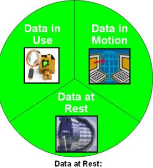
2. Data at Rest, Data in Transit, and Data in Use
Data can exist in any one of three states, as illustrated in Figure 14 (Ball 2013). The states are “data at rest,” “data in transit,” and “data in use.”
Figure 14. The three states of data are “data in use,” “data at rest,” and “data in motion” (from Ball 2013).
Data Loss Prevention (DLP) is one type of methodology to identify, monitor, and protect information. There are many ways to do this, such as deep inspection, contextual security analysis of transactions, and finally through a central management framework. The first purpose of the DLP systems is to detect unauthorized use of information that should remain confidential. The second purpose is to prevent unauthorized use of information that should remain confidential. Finally, the last purpose is to prevent unauthorized transmission of the data (Norton 2011).
For data at rest, DLP can be achieved by locating and cataloging sensitive information stored. While monitoring and controlling the movement of sensitive information across the enterprise network is essential for data in motion/transit, the same can be said for monitoring and controlling the movement of sensitive information on end-user systems for data in use or in a process.
a. Data at Rest (Stored Data)
Data at rest refers to data that is not in used and is stored on a storage device such as a hard disk, CD/DVD, or flash memory device in the form of files or database. Data protection for the data at rest state can be in the form of data encryption and access logging.
b. Data in Motion/Transit (Transmit Data)
Data in motion or transit refers to data that is being transmitted or moving between applications (within the computer) or networks (within a network) using available communication linkage such as a local area network (LAN), Wifi, or computer bus. Data protection for data in transit can be in the form of constant monitoring and protection of data such as Transport Layer Security (TLS), Secure Sockets Layer (SSL), and Internet Protocol Security (IPsec) protocols, and usage of data loss prevention software. Protocols such as TLS, SSL, and IPsec encrypt data packets for secure transportation and decryption by authorized parties. Data loss prevention software monitors network traffic to help prevent unauthorized transmission of data within and exiting enterprise network. In addition, there should be a policy implemented to prevent a user’s negligence in data handling.
c. Data in Use/Process
Data in use are data that are actively being read, modified, or managed by an application, and the data is stored temporarily in memory, such as random-access memory (RAM) or Page Files. This is the most vulnerable state as the data must allow changes to be made and are not protected from attack; therefore, the data requires constant monitoring. Data protection for data in use can be achieved by ensuring access only by trusted applications or authorized users, preventing snooping by third-party applications, and employing full memory encryption.
3. Cyber Sensors for Information Assurance
This section provides a brief background on cyber sensors in general, based out of previous research (Goshorn 2009).
There are two ways of deploying cyber sensors in general. They are classified by where are the monitoring is required—that is, monitoring of the network or monitoring of network devices, also known as the host. Therefore, cyber sensors can be generally categorized by the location in which they have been deployed, either network based or host based (Deptula 2013).
Specific to automating information assurance, network-based cyber sensors are used to monitor information in the state of data in transit, while host-based cyber sensors are used to monitor information in the state of data at rest and data in use.
Furthermore, automation of information assurance requires the data to be monitored for loss of confidentiality, integrity, and availability. Therefore, when choosing sensors, not only is the data state important, the ability to capture the probabilities of the data maintaining confidentiality, integrity, and availability, based on extracted features of the sensor data, is important. This concept is further discussed in Chapter III.
E. CRITICAL SECURITY CONTROLS
The SANS Institute worked with information assurance and cybersecurity experts from government and industry to determine the highest priority controls that one could employ in order to have an effective cyber defense system. For example, information assurance requires data’s confidentiality, integrity, or availability is preserved. Recommendations put forward by the SANS Institute’s Critical Control 17 describes the application of Data Loss Prevention (DLP) in order to actively monitor both data at rest and data in transit (SANS Institute 2014). This control provides the initial concept for achieving information assurance of the data.
systems. The eight controls used in this thesis are described subsequently, with the most relevant control being Control 17 (SANS Institute 2014).
1. Critical Control 1: Inventory of Authorized and Unauthorized
Devices
Control 1 requires that an organization detects and maintains an up-to-date inventory of both authorized and unauthorized devices within the network (SANS Institute 2014). This concept is depicted in Figure 15.
2. Critical Control 3: Secure Configurations for Hardware and Software on Mobile Devices, Laptops, Workstations, and Servers
Control 3 requires that organizations ensure their hardware and software for mobile devices, laptops, workstations, and servers are configured for security (SANS Institute 2014). This is depicted Figure 16.
Figure 16. Control 3 system entity relationship diagram (from SANS Institute 2014).
3. Critical Control 10: Secure Configurations for Network Devices
Control 10 requires that all network devices (such as routers, firewalls, switches) are configured for security, as depicted in Figure 17 (SANS Institute 2014).
Figure 17. Control 10 system entity relationship diagram (from SANS Institute 2014).
4. Critical Control 11: Limitation and Control of Network Ports, Protocols, and Services
Control 11 requires that network ports, protocols, and services within each computer system on a network be limited to allow input and output of required data doing required services (SANS Institute 2014). This concept is depicted in Figure 18.
Figure 18. Control 11 system entity relationship diagram (from SANS Institute 2014).
5. Critical Control 13: Boundary Defense
Control 13 requires that a network have layers of defense by employing protective/monitoring systems throughout the network to create hierarchical boundaries in the network (SANS Institute 2014). This concept is depicted in Figure 19.
Figure 19. Control 13 system entity relationship diagram (from SANS Institute 2014).
6. Critical Control 14: Maintenance, Monitoring, and Analysis of Audit Logs
Control 14 requires that all organizations maintain, monitor, and actively analyze logs that audit both the network and the systems on the network (SANS Institute 2014). This concept is depicted in Figure 20.
Figure 20. Control 14 system entity relationship diagram (from SANS Institute 2014).
7. Critical Control 17: Data Loss Prevention
Control 17 requires that the network be actively monitoring for data loss by employing scanning devices on data storage systems as well as on the network (SANS Institute 2014). This concept is depicted in Figure 21.
Figure 21. Control 17 system entity relationship diagram (from SANS Institute).
8. Critical Control 19: Secure Network Engineering
Control 19 requires that the engineering that goes into architecting and implementing an organization’s network should be inherently secure in its design (SANS Institute 2014). This concept is depicted in Figure 22.
Figure 22. Control 19 system entity relationship diagram (from SANS Institute).
F. SYSTEMS ENGINEERING PROCESS
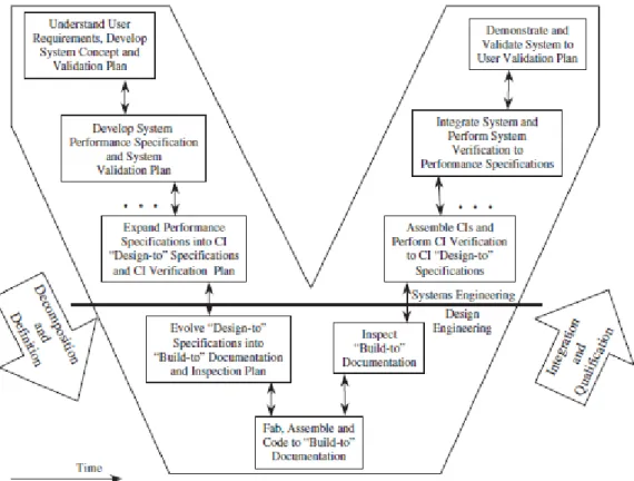
This section gives a brief review of the systems engineering model, the Vee model, used in architecting the new capability presented in this thesis (Buede 2009).
The Vee model represents the lifecycle development of large scale systems and software development projects, with an emphasis on the engineering process for a system being developed. The left side of the Vee represents the beginning three phases of life cycle development. The process starts from the top left of the Vee with the definition of
each component. The horizontal line that is drawn under the middle intersection of the Vee represents the start of the design process of the product by the discipline engineers. Examples of such are electrical engineers, mechanical engineers, chemical engineers, civil engineers, aerospace engineers, and computer science engineers. The horizontal line also represents the part of the process in which there is overlap between the design and integration activities. The right side of the Vee indicates the integration and qualification activities of the system engineering. It involves putting together the lower-level components into higher level components and finally the assembly of high-level components into the system. All the activities up the Vee involve validating and verifying the newly assembled system elements to determine that each element meets the requirements or specifications that were established in the design phase and that the system meets the stakeholders’ needs (Buede 2009).
III.
PROPOSED ARCHITECTURE
Recall that in Chapter I we reviewed products generated during the conceptualization phase of the solution presented in this thesis. This is the first phase of the systems engineering Vee model, as introduced in Chapter II. This chapter reviews products implemented in the following phases of the Vee Model. Namely, the first section reviews the operational scenarios analysis to develop the system performance and requirements. Next, the functional definition and decomposition is conducted to determine the required functions of the system. The IDEF0 function modeling method is used to model the system data flow and control of the proposed IASA system. Requirements analysis will provide the starting point for tracing of the physical solution to the system requirements. Mapping of the physical solution to the functions of the IASA is shown in the form of traceability matrix. The validation and verification of a portion of the proposed system will be discussed in Chapter IV in the proof-of-concept section. As this thesis is focused on the functions of IASA, the physical architecture will similarly focus on the physical architecture of IASA only, as highlighted in Figure 24.
A. CYBER SITUATIONAL AWARENESS AND COMMAND AND
CONTROL SYSTEM OF SYSTEMS CONCEPT
This thesis proposes a system of systems engineering methodology for integrating and configuring an intelligence automation system for the purpose of enabling cyber command and control (C2) and cyber situational awareness (SA). This methodology includes performing the systems engineering process to at least one of the supporting systems. To approach this topic, this thesis first proposes an overarching system of systems architecture demonstrating how systems work independently and together for enabling command and control and providing cyber situational awareness. This system of systems is depicted in Figure 24. It is first made up of the overarching Cyber SA and C2 (CSAC2) system, followed by the Cyber Attack Detection SA (CADSA) system, and finally, the Information Assurance (IA) SA (IASA) system. This thesis will document the high-level system of systems architecture while focusing on the progress of the systems
process is applied to the IASA system. After going through the systems engineering process and generating an architecture with an analysis of alternatives, this thesis implements and describes an instantiated proof-of-concept system of a portion of the IASA system, with documented test and evaluation results.
The initial requirements of this system of systems are documented as needing to be capable of (1) monitoring information assurance of information within specified systems in a cloud framework, along with (2) monitoring for specific cyber attacks on a specified system, (3) alerting information of interest to an operator, and finally (4) allowing the end user to perform command and control over his or her cyber assets.
Figure 24. Focus on IASA in the cyber situational awareness system of systems of specified information in the cloud (boxed in red).