is an open access repository that collects the work of Arts et Métiers ParisTech
researchers and makes it freely available over the web where possible.
This is an author-deposited version published in: https://sam.ensam.eu
Handle ID: .http://hdl.handle.net/10985/8214
To cite this version :
Sajid-Ullah BUTT, Jean-François ANTOINE, Patrick MARTIN - A Kinematic Approach for 6-DOF Part Positioning In: 23rd CIRP Design Conference, Bochum, Germany, Germany, 201303 -Smart Product Engineering, Lecture Notes in Production Engineering - 2013
Any correspondence concerning this service should be sent to the repository
M. Abramovici and R. Stark (Eds.): Smart Product Engineering, LNPE, pp. 147–157.
DOI: 10.1007/978-3-642-30817-8_15 © Springer-Verlag Berlin Heidelberg 2013
Sajid Ullah Butt1, Jean-Francois Antoine2, and Patrick Martin3
1
CEME, National University of Sciences and Technology (NUST), Islamabad, Pakistan
2 GMP, Le Montet, Rue du Doyen Urion, 54601, Villers-lès-Nancy, France 3
LCFC, Art et Métiers, 4 Rue Augustin Fresnel, 57078 Metz, France
[email protected], [email protected],
Abstract. This article proposes a fixturing system consists of a cuboid
basep-late located through a 3-2-1 configuration of locators. The locators are mounted on machine table/pallet and posses one axial DOF. The workpiece is mounted on the baseplate and all the elements are assumed to be rigid with zero friction. The positioning error of the workpiece is calculated and the compensation is performed by the axial movement of the locators. The proposed analytical mod-el is verified by the simulation performed in the CAD modmod-el.
Keywords: Analytical model, Fixturing system, Part positioning, kinematic
model.
1
Introduction
There is a competition in the manufacturing industry to design and deliver a variety of high quality products to their customers in the shortest time. Due to rapid change in production technology and customer demand, the manufacturers need to develop flex-ible manufacturing practices to achieve a rapid turnaround in product development [1]. Among other factors, the use of feasible fixtures is one of the factors influencing the final part’s quality. Fixtures are devices used to support, locate and hold a workpiece at a desired position and orientation in machine’s workspace during manu-facturing. The final part’s quality is influenced by the capability of the fixture to pre-cisely hold and locate it on the machine considering different functional conditions during fabrication. About 10-20% of total manufacturing cost is associated with the fixtures in traditional FMS systems [2]. The design of fixtures is important to precise-ly hold the workpiece and compensate the errors that the workpiece can encounter during machining or assembling operation, so that higher product’s quality can be ensured [3].
The need of high quality production, at lower cost, has accelerated the research ef-forts in fixture design. To cope with current market demand, Ryll et al. [4] emphasize on the need of “intelligent” fixtures which should be capable of self-configuring; reducing and compensating dimensional errors; providing stability and adapting
clamping forces to guarantee optimum performances. This fixture should be generic and should be able to adapt to different workpiece configurations.
2
Positioning Errors
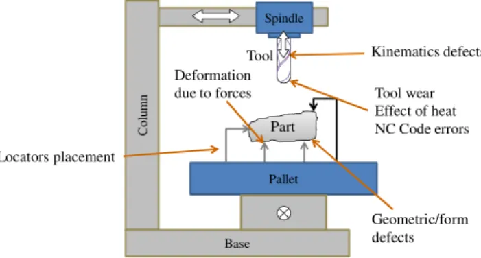
Dimensional errors of the parts from a part family cause the initial misplacement be-tween the workpiece and machine tool affecting the final product quality. The possi-ble causes of the positioning errors between the machine tool and the workpiece are shown in Figure 1, which are:
• Error due to the placement of locators [5–8] • Geometric/form defects of the workpiece [9–12] • Errors due to deformation of locators [13–18] • Kinematic defects/ machine tool errors [19–26] • Misc. errors due to tool wear, heat, NC codes, etc…
Part Pallet Co lu m n Base Spindle Kinematics defects Locators placement Geometric/form defects Deformation
due to forces Tool wear Effect of heat NC Code errors Tool
Fig. 1. Errors between the machine tool and the workpiece
Rough workpiece’s dimensions are varied from one part to another, so the machin-ing allowances have to be added. Even after the addition of allowances, the rough workpiece may not be completely included in required position, which causes the wastage of the workpiece due to incomplete machining. To avoid the loss of time and material, it is necessary to precisely place each new part relative to machine tool. But this placement needs a mobilization mechanism on the machine. This mechanism should assure the kinematic transformation to place the workpiece at an optimal posi-tion by compensating the posiposi-tioning error between the workpiece and the machine-tool. A high number of degrees of freedom (DOF) machine would be an easy way to perform this compensation.
In an existing serial production environment, the global choice of 5-axis machines in the whole production line is not an economically feasible choice. So a new fixtur-ing system is proposed. This fixturfixtur-ing system is able to perform a 6 DOF workpiece’s repositioning on a low DOF production machine through the axial motion of 6
sup-porting locators placed at 3-2-1 configuration. The initial and final positions of the workpiece are given as the input data and an algorithm calculates the positioning error and the axial displacement of each locator required to compensate this positioning error.
The proposed system can be used on the existing machines as well as on automatic production lines where the number of axis is limited for each station. The proposed system allows better positioning of the workpiece on the fixture and hence limiting the required allowances. It also insures a prepositioning of complex parts for precise machining operations. The necessary geometric and kinematic models of the proposed fixturing system are presented in this article.
Y3 Z3 X3 X Z Y O b P XP ZP YP 6 4 5 2 3 1
Fig. 2. Proposed fixturing system principle
3
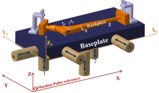
Proposed Fixturing System
This article proposes a fixturing system consists of a set of six locators whose posi-tions and orientaposi-tions are defined through locating holes of the machine table/pallet, a cuboid baseplate, and a workpiece fixed on the baseplate as shown in Fig. 2. Hip prosthesis is chosen as the demonstrated workpiece because it requires repetitive ma-chining operation on expensive material and the dimensions of part change according to patient need. The baseplate is introduced because when the locators are directly in contact with the rough workpiece surfaces, it is impossible to attain the precise positioning of the workpiece through the axial displacement of 6 locators due to un-certainty of the contacting points caused by the local geometrical defect at rough con-tacts. The positioning surfaces of the baseplate are considered to be perfectly plane and orthogonal. This assumption causes the surface normals to always remain parallel to the contacts’ normals, which enables us to predict the exact location of the work-piece by the locators’ positions. Thus the addition of intermediate baseplate avoids this positioning uncertainty: kinematic model will be independent of part geometry.
The locators are assumed to be in a 3-2-1r configuration [27] and possess only one axial DOF. The lateral position of each locator is chosen by considering the con-straints of accessibility, stability of the workpiece and manufacturing knowledge. It is
also assumed that the workpiece is mounted rigidly on the baseplate and no additional deformation occurs between workpiece and baseplate except those caused during clamping the workpiece.
3.1 Analytical Formulation
For kinematic analysis, all the elements of the fixturing system are assumed to be rigid. It is assumed that the positioning error of the baseplate is negligible as com-pared to the positioning error of the workpiece. Also the unknown initial position of the workpiece could imply large displacements (LD) during correction phase; the kinematic model is built using homogeneous transformation matrices (HTM) and LD formulation. The initial position of the workpiece can be measured through CMM while its final position is the position according to which the machine tool is pro-grammed. This position is known by the part program. These positions are compared and if the difference is more than the allowed tolerance, the algorithm calculates the unique relative axial position of each locator to relocate the workpiece at the required position. 0.00 10.00 20.00 30.00 40.00 50.00 60.00 70.00 80.00 90.00 -10.00 10.00 30.00 50.00 70.00 90.00 110.00 130.00
Min Material (Chebyshev)
Y
X
Stem
Neck
P
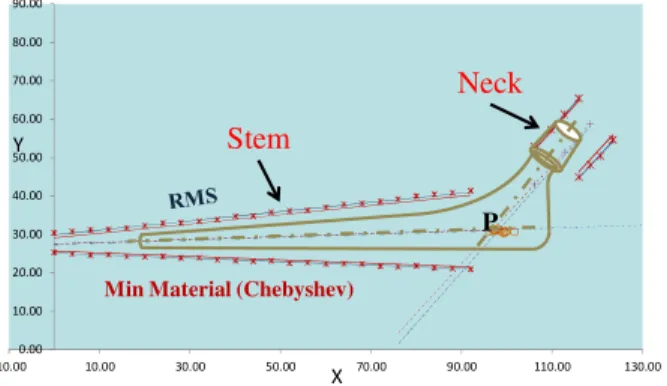
Fig. 3. 2D Demonstration of measurement though CMM
The measurement principle of the hip prosthesis though CMM (in 2D) is shown in Fig. 3. Rough part dimensions are larger than the final product. Random measured points are generated in MS Excel for stem and neck of the hip prosthesis. RMS and Chebyshevs’ surface association criteria are presented [28], [29], and theoretical cen-terlines (for neck and stem) are then deduced. The angle between these cencen-terlines should be under the tolerance range. Point P denotes the intersection of centerlines. In 3D space, the definition of point P, in machine reference, cancels 3 DOF; the defini-tion of the XY plane cancels two more DOFs and the last DOF is canceled by defin-ing the angle of stem axis with XZ plane, completdefin-ing workpiece placement in the machine space. Some position variations among the parts of the same part family will remain. Random measuring points are generated and the point P is calculated for each set of measuring points. The generated distribution of P is also presented in Fig. 3.
The HTM of cuboid baseplate position is the function of its surface normals calcu-lated from the positions of the six locators [12]. This HTM is shown in Eq. (1) where a, b and c are the unit vector components; 1, 2 and 3 are the unit vectors in Z, Y and X directions while xb, yb and zb are the coordinates of baseplate origin.
[ ] = 1 0 0 0 z c c c y b b b x a a a P b 1 2 3 b 1 2 3 b 1 2 3 Ob (1)
Similarly, the HTM of the workpiece position in machine coordinates is defined con-sidering YPR transformation as shown in Eq. (2) with α, β and γ being the rotations along Z, X and Y axes respectively.
[ ] γ β β γ β − γ β α − γ α β α γ β α + γ α γ β α + γ α β α − γ β α − γ α = 1 0 0 0 z cos cos sin sin cos y cos sin cos sin sin cos cos sin sin cos cos sin x cos sin sin sin cos cos sin sin sin sin cos cos P P P P OP (2)
Positioning transformation scheme of the proposed fixturing system is shown in Fig. 4 where Xi represents the position vector of reference iwhile [Pij] represents the
trans-formation matrix from position i to j. The HTM of the baseplate with respect to ma-chine reference ([POb]) is calculated from the locators’ initial positions. The
transfor-mation of the workpiece relative to the machine ([POP]) can be measured through
CMM. Thus the required transformation of workpiece with respect to baseplate ([PbP])
is deduced and HTM of the error compensation ([POb’]) is calculated as shown in Eq.
(3). Final absolute positions of all the six locators, required to compensate the work-piece positioning error, are shown in Eq. (4).
XO XP XF Xb Xb’ [Pob] [POb’] [PbP] [Pb’F] [PPF]
Machine reference = Pallet reference Initial measured position of the workpiece Final position of the workpiece (Objective) Initial position of baseplate
Final position of baseplate
HTM of baseplate in machine reference HTM of baseplate in machine reference HTM from baseplate to workpiece HTM from baseplate to workpiece (Pb’F=PbP) Workpiece positioning error (Pbb’=PPF)
Calculation path Rigid link XF Xb’ XO Xb XP [PPF] [PbP] [Pb’F]=[PbP] [POb’] [P Ob] Correction [PPF] Error to be corrected Rigid link Correction through locators Initial placement of baseplate on the locators
Fig. 4. Fixturing system reference transformation
[ ] [ ] [ ] [ ] [ ][ ]1 bP OF ' Ob OP 1 Ob bP P P P P P P − − = = (3)
[ ] [ ] [ ] [ ]
(
)
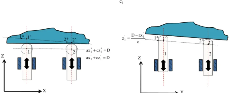
1 ' Ob 1 Ob OF ' b ' 1 ' 2 ' 3 ' b ' 1 ' 2 ' 3 ' b ' 1 ' 2 ' 3 ' Ob P P P 1 0 0 0 z c c c y b b b x a a a P = − − = (4)The resolution of the above equations give the positions of locators which are imposs-ible to attain because the contacting points of locators on the baseplate change as a result of rigid body motion of the baseplate on locators. This is shown with a 2D ex-ample in Fig. 5, where the final calculated positions of the arc centers of locators are shown by 1* and 2*. Due to the constraint of uniaxial motion, the locators cannot be advanced to these positions. To overcome this mathematical issue, a line is drawn between the points 1* and 2* (plane in our case of 3D), and the points of intersections of this line with the locators’ axes are calculated. Moving the locators at these calcu-lated positions will enable us to perform the required workpiece transformation. In the same manner, axial advancements of all the six locators are calculated through the contacting points of all three contacting surfaces. The final axial position of locator 1 is shown in Eq. (5) witha ,1' b and '1 c being the unit vector components of the ba-1' seplate surface. The advancements of the rest of the locators are deduced similarly.
' 1 1 ' 1 1 ' 1 1 ' 1 c y b x a D z = − − (5) Z X 1* 1’ 2* 2’ 1 2 Z X 1* 2* 1’ 2’ 1 2 D cz ax D cz ax ' 1 ' 1 * 1 * 1 = + = + c ax D z ' 1 ' 1 − = ( a )d r a w i n g l i n e a n d c a l c u l a t i n g n e w a x i a l p o s i t i o n s ( b )p e r f o r m a d v a n c e m e n t
Fig. 5. Calculating the axial advancements of locators
3.2 Case Study
In order to validate the kinematic model, a case study is performed on a hip prosthesis repositioning through CATIA® simulation. A CPT® 12/14 Hip Prosthesis by Zimmer [30] is chosen as a demonstrative workpiece. The part is created in CATIA® with slightly larger dimensions and supports are added. It is supposed that this workpiece is clamped rigidly on the baseplate which is further located through six rigid locators. An inverse impression of the workpiece (like a half die) is created with the original hip prosthesis dimensions and is placed on a fixed position with reference to the ma-chine origin. This position represents the tool path on the mama-chine as the tool moves with reference to machine and not with reference to workpiece. Boolean operation is
performed to simulate the machining operation by subtracting the common material from the workpiece. Two slots are made in the supports during machining of the first half part which will help to place the workpiece on two well positioned blocks after inverting.
The analytical model is implemented in a worksheet directly linked to CATIA® model which furnishes the initial position ([POP]) of the workpiece as shown in table
1(a). This position should be obtained by CMM in real environment. The initial posi-tion of the baseplate ([POb]) is a function of locators’ positions shown in Table 1(b).
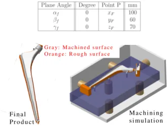
The machining performed on this initially roughly placed workpiece is shown in Fig. 6. The workpiece should be repositioned at the required position ([POF]) to perform a
precise machining operation. This final position is known by the part program and is shown in the Table 2.
Table 1. Initial positions of locators and the workpiece
(a) Initial locators’ positions (Axial
po-sitions are highlighted) (b) Initial workpiece position
Table 2. Required position of the workpiece (Objective)
G r a y: M a c h i n e d s u r f a c e O r a n g e : R o u g h s u r f a c e F i n a l P r o d u c t M a c h i n i ng s i mu l a t i o n
Fig. 6. Machining simulation on the workpiece at initial position
The algorithm calculates the final axial positions of all the six locators (Table 3) to compensate the workpiece positioning error. The locators are moved to these new
positions and the machining simulation is performed. This time the material re-moval was uniform throughout the workpiece as shown in Figure 7.
F i n a l
P r o d u c t M a c h i n i n g s i mu l a t i o n
Fig. 7. Machining simulation on the workpiece after repositioning
Table 3. Calculated final position of the six locators (Axial positions are highlighted)
Simple investigation reveals that the workpiece was not at the exact required posi-tion. The 6 DOF repositioning error of the workpiece is shown in Table 4(a) while the same for the second side is shown in Table 4(b). This positioning uncertainty is due to the limited advancement precision (10 μm) of locators. This positioning uncertainty can be expressed as robustness of the proposed model.
Table 4. Workpiece positioning error due to locators' precision
(a) First side of the workpiece (a) Second side of the workpiece
3.3 Robustness of the Model
The workpiece position uncertainty is calculated from the Plucker coordinates[31] as the function of precision of locators’ advancements. In our case, using the locators’ input positions (Table 1. Initial positions of locators and the workpiece(a)), the uncer-tainty at reference point P (Table 2) is deduced as a function of six advancements,
(6)
where, dz1, dz2, dz3, dy4, dy5 and dx6 are uncertainties of the locators’ advancements.
In order to calculate the maximum positioning error, all the term are arranged so that their effect is added to the positioning error. The right most vector in Eq. (6) is the maximum positioning error as the function of precision of locators’ advancements ξ, in our case, assumed to 10μm.
4
Conclusion
A fixturing system has been proposed which is capable of performing the compensa-tion of the posicompensa-tioning error of the workpiece through the advancement of six locators. To allow a repetitive repositioning of irregular parts, a baseplate has been placed in between the machine table and the workpiece. The baseplate has been located through a 3-2-1 locating configuration and all the fixturing elements were considered to be rigid. The kinematic model calculated the locators’ advancements which enabled us to relocate the workpiece indirectly by baseplate relocation. The kinematic model has been simulated in CATIA and the results verified the analytical model.
References
1. Boyle, I., Rong, Y., Brown, D.C.: A review and analysis of current computer-aided fixture design approaches. Robotics and Computer-Integrated Manufacturing 27(1), 1–12 (2011) 2. Zhang, W.: Flexible fixture design and automation: review, issues and future directions.
International Journal of Production Research 39(13) (2001)
3. Butt, S.U., Antoine, J.F., Martin, P.: An Analytical Model for Repositioning of 6 D.O.F Fixturing System. Mechanics & Industry, 13 (2012) (in Press)
4. Ryll, M., Papastathis, T.N., Ratchev, S.: Towards an intelligent fixturing system with rapid reconfiguration and part positioning. Journal of Materials Processing Technology 201, 198–203 (2008)
5. Li, B., Melkote, S.N.: Improved workpiece location accuracy through fixture layout opti-mization. International Journal of Machine Tools and Manufacture 39(6), 871–883 (1999) 6. Somashekar, S.: Fixturing features selection in feature-based systems. Computers in
Indus-try 48(2), 99–108 (2002)
7. Roy, U., Liao, J.: Fixturing Analysis For Stability Consideration in an Automated Fixture Design System. J. Manuf. Sci. Eng. 124(1), 98–104 (2002)
8. Wang, M.Y.: Tolerance analysis for fixture layout design. Assembly Automation 22(2), 153–162 (2002)
9. Bourdet, P.: Logiciels des machines à mesurer tridimensionnelles. Techniques de l’ingénieur. Mesures et contrôle, no. R1316, pp. R1316–1 (1999)
10. Clement, A., Bourdet, P.: A Study of Optimal-Criteria Identification Based on the Small-Displacement Screw Model. CIRP Annals - Manufacturing Technology 37(1), 503–506 (1988)
11. Villeneuve, F., Legoff, O., Landon, Y.: Tolerancing for manufacturing: a three-dimensional model. International Journal of Production Research 39(8), 1625–1648 (2001) 12. Asante, J.N.: A small displacement torsor model for tolerance analysis in a workpiece-fixture assembly. Proceedings of the Institution of Mechanical Engineers, Part B: Journal of Engineering Manufacture 223(8), 1005–1020 (2009)
13. Jayaram, S., El-Khasawneh, B.S., Beutel, D.E., Merchant, M.E.: A Fast Analytical Method to Compute Optimum Stiffness of Fixturing Locators. CIRP Annals - Manufacturing Technology 49(1), 317–320 (2000)
14. Raghu, A., Melkote, S.N.: Modeling of workpiece location error due to fixture geometric error and fixture-workpiece compliance. Journal of Manufacturing Science and Engineer-ing 127, 75 (2005)
15. Hurtado, J.F., Melkote, S.N.: Improved Algorithm for Tolerance-Based Stiffness Optimi-zation of Machining Fixtures. J. Manuf. Sci. Eng. 123(4), 720–730 (2001)
16. Asante, J.N.: Effect of fixture compliance and cutting conditions on workpiece stability. The International Journal of Advanced Manufacturing Technology 48(1), 33–43 (2010) 17. Marin, R.A., Ferreira, P.M.: Analysis of the Influence of Fixture Locator Errors on the
Compliance of Work Part Features to Geometric Tolerance Specifications. J. Manuf. Sci. Eng. 125(3), 609–616 (2003)
18. Liao, Y.G., Hu, S.J.: An Integrated Model of a Fixture-Workpiece System for Surface Quality Prediction. The International Journal of Advanced Manufacturing Technology 17, 810–818 (2001)
19. Hsu, Y.Y., Wang, S.S.: A new compensation method for geometry errors of five-axis ma-chine tools. International Journal of Mama-chine Tools and Manufacture 47(2), 352–360 (2007)
20. Lin, Y., Shen, Y.-L.: A Generic Kinematic Error Model for Machine Tools. Citeseer (2000)
21. Ahn, K.G., Cho, D.W.: An analysis of the volumetric error uncertainty of a three-axis ma-chine tool by beta distribution. International Journal of Mama-chine Tools and Manufac-ture 40(15), 2235–2248 (2000)
22. Choi, J.P., Min, B.K., Lee, S.J.: Reduction of machining errors of a three-axis machine tool by on-machine measurement and error compensation system. Journal of Materials Processing Technology 155, 2056–2064 (2004)
23. Jha, B.K., Kumar, A.: Analysis of geometric errors associated with five-axis machining centre in improving the quality of cam profile. International Journal of Machine Tools and Manufacture 43(6), 629–636 (2003)
24. Zhu, S., Ding, G., Qin, S., Lei, J., Zhuang, L., Yan, K.: Integrated geometric error model-ing, identification and compensation of CNC machine tools. International Journal of Ma-chine Tools and Manufacture 52(1), 24–29 (2012)
25. Martin, P., Dantan, J.Y., D’Acunto, A.: Virtual manufacturing: prediction of work piece geometric quality by considering machine and set-up accuracy. International Journal of Computer Integrated Manufacturing 24(7), 610–626 (2011)
26. Wan, X.-J., Xiong, C.-H., Zhao, C., Wang, X.-F.: A unified framework of error evaluation and adjustment in machining. International Journal of Machine Tools and Manufac-ture 48(11), 1198–1210 (2008)
27. Paris, H.: Contribution à la conception automatique des gammes d’usinage: le probléme du posage et du bridge des pièces. Université Joseph Fourier Grenoble (1995)
28. Dursapt, M.: Aide-mémoire métrologie dimensionnelle. Dunod (2009)
29. Bourdet, P., Schneider, F.: Spécification géométrique des produits: cotation & tolé-rancement ISO (Coll. Technique & ingénierie). DUNOD, Paris (2007)
30. zimmer, CPT 12/14 cemented stems (September 2011),
http://www.zimmer.co.uk/web/...14_Hip_Syste_97-8114-01_rev_1.pdf
31. Halevi, G., Weill, R.D.: Principles of Process Planning: a Logical approach. Chapman and Hall, London (1995)