Visual Modelling and Managing the
Software Architecture Landscape in a large Enterprise
by an Extension of the UML
Marcus Heberling1, Christoph Maier2, Thomas Tensi3
Abstract
In large enterprises the number of software systems for diverse tasks is very high. They have different technical platforms and design philosophies but nevertheless are intensely con-nected. Hence to deal with the complexity of such a application network some software architecture management is necessary.
The ARCUS method in the Bayerische Landesbank defines domain-specific visual language for modelling the architecture of a complete landscape of software via the Unified Modelling Language. This is achieved by extending the UML metamodel with new stereotypes and con-straints and by introduction of new notions like e.g. the derived relations. To implement this method tools are vital, but also new roles within the organisation have to be established.
1. Introduction
Large enterprises normally have a zoo of applications with different technical realisations and design concepts. Nevertheless those applications are normally intertwined intensely. Some-times an application uses information provided by another; someSome-times the application have an overlap in the data used or even in the algorithms used.
Traditionally applications are developed and maintained by only looking at their immediate context. This means that there is no global view of dependencies and possible redundancies. This leads to problems like e.g.
- business requirements cannot be traced to applications,
- small changes in a single application may lead to avalanche changes in other applica-tions, and
- planning strategic changes (like e.g. mass migration to decentralised systems) is im-possible.
Hence the typical management of architecture-in-the-small is not sufficient. There must be a global view of the single applications' architecture and the architecture-in-the-large of all ap-plications (their interconnection, commonly used components etc.). Otherwise one will get a heterogeneous global architecture and problems with algorithmic or data redundancies. Based on those ideas the Bayerische Landesbank, Munich, started the ARCUS project four years ago. Its aim was to develop a notation and tool set to support the architecture manage-ment within the enterprise and also to decide how to embed this managemanage-ment into the organisation.
Also a method for creating and maintaining architecture models has been developed. Due to the limited space and scope of the paper we will not go into details of this method.
1 Marcus Heberling, F.A.S.T. GmbH, Arabellastraße 17, D-81925 München
2 Dipl.-Inform. (univ.) Christoph Maier, Bayerische Landesbank, Briennerstraße 20, D-80333 München 3 Dr. rer. nat. Thomas Tensi, sd&m AG, Thomas-Dehler-Straße 27, D-81737 München
2. Goals,
Purpose
and
Audience
of Architecture Management
The main purpose for an architecture management is to ensure the compatibility of all hard-ware and softhard-ware systems used within the enterprise. As already mentioned it does not suffice to simply put together the individual application models or to have a broad view on all applications, but have them both in a single model.
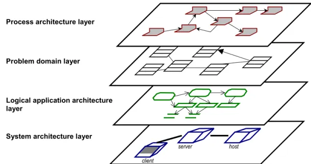
The architecture model contains several layers, containing different aspects of a software sys-tem. Those layers form a hierarchy and are connected; hence it is useful to keep them together in a single model. As layers we have a broad model of the business processes, a class model of the business notions, an abstract model of the applications' logical components and a tech-nical model of hardware and software components.
Business processes and notions are independent of an implementation on a computer. Both layers together cover the dynamic and static aspects of the business. The component model describes the conceptual, the technical model describes the real implementation architecture. They could be isomorphic but in practice often are not.
Of course, due to the high complexity it is neither possible nor necessary to precisely model every aspect of an application in the central model. The central architecture model is just a macroscopic view of the application landscape. Detailed information about a single applica-tion is stored in the different development environments. That informaapplica-tion can be abstracted in the central model because many implementation details do not affect the architecture of the application.
In that respect the application landscape model resembles a zoning plan for a city: here you are interested in what kind of buildings are put at some place and the zoning plan reveals how the structure will develop. Nevertheless details of buildings (like the shape of the window frames) is irrelevant.
Covering all those aspects and connecting them in the model allows to find out how
- business processes are supported by applications,
- new business requirements may change existing applications,
server host client
Process architecture layer
System architecture layer Problem domain layer
Logical application architecture layer
- existing model parts or components might be reused, and
- the existing application landscape might be simplified by restructuring.
The architecture model addresses mainly two audiences: the management and the developing projects. Management gets some ideas how business problem domains are supported by IT and how improvements could map into the IT domain; the projects know their context early, especially with respect to interfaces and possible reuse of existing solutions.
Based on the intended purpose and the target audience, ARCUS has several goals:
- establishing a common vocabulary for the topics of "software architecture" and "appli-cation landscape"
- realisation of a simple notation for software architecture based on a standard notation
language and
- systematic and abstract representation of the enterprise's existing and target
architec-ture.
Additionally architecture management had to be embedded into the enterprise. A central ar-chitecture management team has been established taking care of an enterprise-wide
application landscape model. This model is also available to architecture teams for the diverse business domains which may selectively change those aspects for which they are responsible and have expertise.
3.
Using the UML as a Base Metamodel for ARCUS
As mentioned before modelling the application landscape is done on four architecture layers (see figure 1). Those layers describe
- the business processes supported by the applications,
- the important business notions in a class model including relations between them, - the logical application components, their interconnection and the processed logical
data and
- the physical computer topology as well as the technical software components
imple-menting the logical application architecture and their relations. It is not sufficient to model the layers seperately but one also has to include
inter-layer-relationsships explicitely, to show dependencies between model elements in the different layers and be able to follow them.
Basis for the ARCUS metamodel is the Unified Modelling Language (UML, see [UML]) which has been extended by ARCUS in several ways:
- Variants of existing UML model elements have been introduced by using stereotypes. The elements of the layers are stereotypes of classes with specific stereotyped
relations. The altogether about 50 stereotypes for classes for a proper hierarchy.
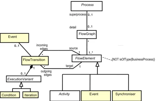
- There are additional rules on how those new model elements can be interconnected. ARCUS defines this in a metamodel which comprises about 80 metamodel elements and more than 60 metarelations. Figure 2 shows a part of the metamodel for the process architecture layer. Here you can see that a process may be refined by a flow graph. The nodes in the flow graph are either activities or events, which are connected by flow transitions (details in section 4.1.). Additional semantic rules are given as
constraints of the metamodel (partly as OCL-constraints, see figure 2 for an example).
- For convenience in modelling the new concept of a detailed class has been introduced.
This is a class element with some encapsulated internal structure, which can be exposed on demand. It is somewhat a mixture between a package and a class (more on that in section 5.1.).
- As the elements form a hierarchy relations on lower hierarchies may induce relations
on upper hierarchies. Those relations do not have to be modelled explicitely but are automatically synthesized as so-called derived relations following special rules (see section )
All those concepts have been implemented by using a commercial case tool and extending it by several modules. Those programs help a modeller to navigate through an architecture model, to check the consistency of the model and to query it or extract other representations from it. The metamodel is parametrized by putting a text definition of it into an external file and can be easily changed.
Due to some restrictions in the UML semantics (or at least in the implementation thereof in the CASE tool used!) all ARCUS model elements are either classes or relations between classes. This design decision gives a very flexible basis for implementing the ARCUS meta-model.
Activity Event Synchroniser
Process 0..1 0..1 detail 0..1 superprocess0..1 FlowElement FlowGraph * 1..* * 1..* {NOT isOfType(BusinessProcess)} FlowTransition * 1 incoming edges * source 1 1 * target 1 outgoing edges * Event 0..1 0..1 ExecutionVariant 0..1 1 0..1 1 Condition Iteration
4.
Architecture Layers in Detail
In this section we illustrate the four architecture layers using an example of a simple and fic-tional travel expense management system.
4.1. Business Process Architecture Layer
This layer describes the business processes concentrating on those directly supported by ap-plications.
The centre of modelling is the role. Here we describe what kind of roles there are, what tasks they are responsible for and how they interact in handling a business process.
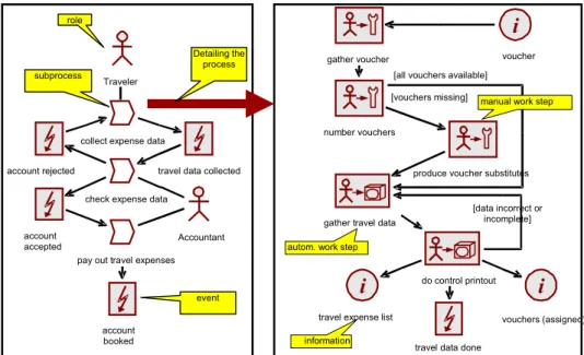
Technically the description is done by flow graphs which are networks of activities, events and connected information flows. The graph is an abstraction of all possible sequences of ac-tivities for the given business process and is very similar to the UML activity diagrams. Base elements are "process", "work step", "event", "information", "organisational unit" and "role". A business process is detailed by a graph of process, work step and event nodes con-nected by flow relations. Also possible are branches, loops and parallelism. The graph may be augmented by relations to information sources and sinks as well as roles and org. units per-forming the process steps.
Figure 3 illustrates this layer with excerpts from the model for the travel expense management system.
Note that the focus of ARCUS is not on replacing standard business process modelling: the ARCUS model is not a business administration view, but a technical view focussing on the IT support of processes. To be able to navigate the model and do meaningful queries the connec-tion to other layers is obligatory (see secconnec-tion 4.5.).
4.2. Problem
Domain
Architecture
Layer
In this layer the business notions are modelled by using types and objects with their static and dynamic relations.
i
voucher gather vouchernumber vouchers
produce voucher substitutes [vouchers missing]
gather travel data
[all vouchers available]
i
vouchers (assigned) travel data donei
travel expense listdo control printout [data incorrect or
incomplete] Traveler
collect expense data
travel data collected account rejected
account accepted
check expense data
pay out travel expenses Accountant
autom. work step
manual work step
information account booked Detailing the process role subprocess event
In principle we here have a simplified analysis class or data model. This means we're not do-ing a complete class model of the application (which is normally very technical and done elsewhere), but modelling the important - mostly inter-application - notions and their relations and constraints.
Hence in this layer we use the standard UML concepts like classes, associations, objects, state models etc. There is only one stereotype added in this layer: the "central notion". It visually emphasises the fact that a class is very important for the enterprise.
This layer is introduced to give an idea, what notions an application uses and supports techni-cally. One now can easily query a model to find applications with overlapping problem domains.
4.3. Logical
Application Architecture Layer
This layer describes the applications and their components from a logical point of view re-gardless of the technical implementation constraints.
The idea is to introduce an intermediate layer which describes how the applications and the application network would be structured when no technical constraints were given. This layer firstly supports people not proficient with technical terms (like most non-IT customers) giving them an abstract view on the application. Secondly normally the abstract application architec-ture is much more stable than the physical.
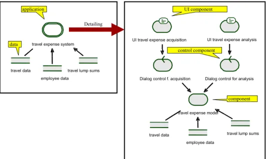
Here the base model elements are "application", "component", "module" and "data" plus vari-ants.
Figure 4 illustrates this layer with excerpts from the model for the travel expense management system.
4.4. System
Architecture
Layer
The architecture layer describes the final implementation architecture of an application and its deployment. It consists of a hardware and software view.
- The hardware view describes the physical computer landscape and the topology but abstracting from concrete systems and considering only archetypes of systems. Hence typical elements are called "data-warehouse server" and not "Machine 3637". As base hardware elements we have "computer", "network" and "physical data". Additionally there are variants and groupings (like "server group").
- The software view describes the technical realisation of an application including
tech-nical components (for communication, middleware etc.) which have been intentionally left out of the logical application architecture. Base software elements are "program"
UI travel expense acquisition UI travel expense analysis
employee data travel data
Dialog control f. acquisition Dialog control for analysis
travel expense model
travel lump sums travel data
employee data
travel lump sums travel expense system
Detailing component UI component control component data application
Figure 4: Example for the logical application architecture layer in ARCUS
Database Server Employee PCs Application Server <<TCP/IP; IIOP>> <<TCP/IP; HTTP>> Accounting PCs client group server station main server <<TCP/IP>> <<TCP/IP>>
Travel Expense Acquisition
Program Travel Expense Database Travel Expense AccountingProgram Software
Hardware
(executables, scripts and third-party products), "physical data" (files and databases) and "software systems" (as clusters of data and programs) with variants.
To model the deployment of the software elements on the hardware elements relations are allowed between specific software and hardware elements.
Figure 5 illustrates this layer with excerpts from the model for the travel expense management system.
4.5. Inter-Layer-Relationships
As we have all layers in one model we can establish relations between them and also query for those connections. Of course, the metamodel restricts the relations allowed to meaningful constellations.
With those relations the model can be approached depending on the modeller: A
proc-ess-oriented modeller can traverse the model top-down to find out what implications a change in a business process might have on the applications; a technically-oriented modeller can trav-erse the model bottom-up finding the effect of changes in the technical application
interconnection on data flow in the process layer.
For easier layer identification the visual representation of the model elements uses a unique colour for all the elements within a layer (see figures 3, 4 and 5 above).
5. Specific
Metamodel
Constructs
There are additional ARCUS-specific metamodel extensions which have proved to be helpful in doing the modelling.
5.1. Detailed
Elements
As already shown in figures 3 and 4 it is convenient to consider at least some elements in the metamodel as detailable.
- A non-detailed element has no internal structure and its visual representation has a
grey background (it's a black box...).
- A detailed element has some internal structure which normally is not shown. Its visual
representation has a transparent background (it's a white box...) and reveals its con-tents on demand.
E.g. in the left part of figure 3 we have a detailed process element "collect expense data" whose detailed structure is shown in the right part of figure 3.
Note that normally not all elements in a detail view are parts of the detailed element (in the sense of an UML aggregation). In our case the work steps and subprocesses of the right part of figure 3 might be parts of "collect expense data", but the involved roles certainly are not. The ARCUS metamodel defines exactly what detailing aggregations the elements may have.
5.2. Derived
Relations
ARCUS allows to handle relations which have not been fixed by the modeller, but are auto-matically generated by the system: the so-called derived relations.
To understand the purpose of those relations, first look at an example: Assume that applica-tion "A" contains a component "A1" and an application "B" contains a component " B1". Let's
also assume "A1" uses "B1". If a view shows "A1" and "B1" then also the usage relationship
between "A1" and "B1" should be visible. Normally the UML-CASE-tool does this
automati-cally. But in a view which only shows "A" and "B" and not their parts ""A1" and "B1" also an implicit usage relationship must be visible between "A" and "B", because some part of "A" uses some part of "B".
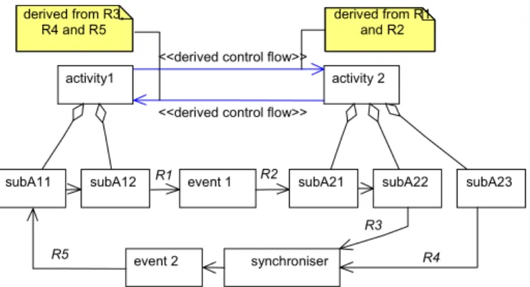
This rule is valid for many such situations and transitively across arbitrary aggregation hierar-chies. The semantic rules of the metamodel clarify exactly when this propagation of relations may occur. It also deals with some technical complications that some elements may be trans-parent with respect to some relations. In figure 6 we have two high level activities with some aggregated subactivities. There is a intersected control flow relation between "subA12" and
"subA21" with some event in between and another between "subA22" and "subA11" with some
synchroniser and event in between. Nevertheless when just coarsening the flow graph to ac-tivities only, we can derive two control flow relations between "activity 1" and "activity 2". But figure 6 does not reveal the whole truth: of course, there are derived relations relations missing (e.g. one between "activity 1" and "subA11" as well as another one between "subA23"
and "subA11"!).
Two remarks are necessary:
- Firstly, it would be quite incomprehensible when all derived relations would be shown
in views. Hence in any view of the model only those relations are visible which are on the lowest hierarchy level shown. If in some view only "activity 1", "activity 2" and " subA21" from the model in figure 6 were visible, the derived relation from "activity 1"
to " subA21" would be shown, but the one from "activity 1" to "activity 2" would not! - Secondly, derived relations are volatile: The system stores how the propagation
oc-curred (see the notes in figure 6 for an example) and generates or deletes the relations automatically. This volatility is also visualised in views by colouring derived relations differently from normal relations.
event 1 subA21 subA22 subA23
synchroniser subA12 subA11 event 2 R1 R2 R3 R4 R5 activity 2 activity1
<<derived control flow>>
derived from R1 and R2 derived from R3,
R4 and R5
<<derived control flow>>
6. Tool
Support
It is impossible to establish architecture modelling according to some notation with a some-times complicated semantics without any tool support. Hence we have implemented add-ins for the common commercial CASE-tool "Rational Rose" which allow to generate, modify and query architecture models and to export architecture models into relational data bases or HTML representations. Figure 7 shows how to specify some simple query for elements in the model.
In most cases modellers will work on the graphic views of the application model. Hence also model queries will offer the opportunity to deliver their output as diagrams. Those diagrams can then be used to selectively change properties of the elements found in the query.
Also as this application landscape will become very large it has to be version-controlled with a fine granularity.
In the moment we are working on a migration to a metamodelling tool which also allows a stronger semantic checking of the model. This is currently only possible a posteriori.
7. Experiences
Initially the focus of the project was to develop some effective add-in for Rational Rose to work with some highly configurable metamodel for architecture modeling. The effort to do this was about two manyears which is little compared to the effort going into consulting the users and promoting the method.
A problem with a highly configurable metamodeling engine is that you might be mislead into putting in "too much stuff" and build a very complex metamodel. We also fell into this trap. In the meantime the granularity of the metamodel has been reduced significantly.
An important lesson learned is that typically an a-posteriori-checking is not done by the mod-ellers, because it hinders them to draw diagrams "freely". A correctness-by-construction approach is much more suited when you need consistency across teams.
8. Summary
In the ARCUS project of the Bayerische Landesbank we have developed a notation and method for modelling software architecture for applications in the large.
Main purpose of architecture management is to make planning of changes in the application landscape possible. By the global view possible synergies can be detected more easily. The basis for the notation of the ARCUS method is the Unified Modelling Language. It was extended by standard mechanisms as well as by defining a new metamodel with additional semantic rules.
All those concepts have been implemented by adding specific modules to a commercial CASE-tool. Additionally some method for developing architecture models has been devised and the architecture management has been embedded into the organisation.
Acknowledgements
The ARCUS system and method has been developped within the last four years by several people. The authors explicitely would like to thank the former project team leaders Sascha Groh, Jörg Hermanns and Fridtjof Toenniessen and the former team members Alessandra Cavarra, Christian Jänsch and Hubert Zweckstetter. ARCUS would not exist without them.
References
[Arch1] Len Bass, Paul Clements und Rick Kazman.
Software Architecture in Practice, Addison-Wesley, 1998
[Arch2] IEEE Recommended Practice for Architectural Description, Draft 4.1 of IEEE P1471, December 1998
(http://www.pithecanthropus.com/~awg/)
[Arch3] SEI – Software Architecture
http://www.sei.cmu.edu/architecture/sw_architecture.html [BPR1] Michael Hammer and James Champy.
Reengineering the corporation–A Manifesto for Business revolution. New York: HarperBusiness, 1993
[BPR2] Ivar Jacobson, Maria Ericsson, and Agneta Jacobson.
The Object Advantage - Business process reengineering with object technol-ogy. Addison-Wesley, 1994
[UML] J. Rumbaugh, G. Booch, I. Jacobson. The UML Reference Guide.