Functional Architecture Modeling for the
Software Product Industry
Sjaak Brinkkemper and Stella Pachidi
Department of Information and Computing Sciences University of Utrecht
P.O. Box 80.089, 3508 TB Utrecht, The Netherlands [email protected], [email protected]
Abstract. Although a lot of research has been carried out on the technical architecture of software systems, the domain of Functional Architecture in the software product industry lacks a formalization of the related concepts and practices. Functional Architecture Modeling is essential for identifying the functionalities of the software product and translating them into modules, which interact with each other or with third party products. Furthermore, the functional architecture serves as a base for mapping the requirements and planning the product releases. Some software vendors intuitively tend to design the functional architecture of their products, but this practice has been unstructured so far and realized only in specific business domains. In this paper, we present the Functional Architecture Diagrams, a powerful modeling tool for the functional architecture of software products, which comprises: a modular decomposition of the product functionality; a simple notation for easy comprehension by non-specialists; and applicability in any line of business, offering a uniform method for modeling the functionalities of software products.
Keywords: software product, functional architecture modeling, modularity
1 Towards Functional Architecture Modeling Attuned to Software
Products
The discipline of software architecture, developed mainly during the last 20 years, is considered to be fundamental for the successful development of software products. According to Bass, Clements & Kazman [4] software architecture: constitutes a common language for the stakeholders −architects, product managers, software engineers, consultants, customers, marketing department− to communicate; captures design decisions in the early stages of a software product, which enable or inhibit implementation attributes and are used as reference in the future for managing change; consists of generalized constructs that can be transferred and reused in other product lines.
According to IEEE Standard 1471 [13], architecture is defined as “the fundamental organization of a system embodied in its components, their relationships
to each other and to the environment and the principles guiding its design and evolution”. A lot of definitions for software architecture have been developed [24], among which we find interesting the view of Johnson [9], who considers architecture as “the set of design decisions that must be made early in a project”.
Architecture viewpoints in software products provide guidelines to describe uniformly the total system and its subsystems. In the sense that the architecture should address the concerns of the stakeholders of the system [13][14], a viewpoint can be understood as a frame that identifies the modeling techniques that should be used to describe the architecture in order to address a defined subset of these concerns. Following the categorization of concepts by Broy et al. [7], we suggest that architecture viewpoints could be divided into three abstraction layers: The functional architecture describes the system by its functional behavior and the interactions observable with the environment. The logical architecture describes the system's internal structure, represented as a network of logical components that implement the system's functionality. The technical architecture describes how the system is realized, its software behavior, and its hardware structure.
A view represents the content of a viewpoint applied to a particular system. According to IEEE Standard 1471 description, view is defined as “a representation of the whole system from the perspective of a related set of concerns” [13]. Numerous sets of views have developed since 1990, amongst which we distinguish Kruchten's “4+1” view model of software architecture [16], the Siemens Four View model [22] and the model proposed by Herzum and Sims [11] in their book Business Component Factory. Furthermore, frameworks from the area of Enterprise Architecture such as Zachman's Framework [27] and TOGAF [8] include sets of architectural views that could also be applied in software architecture.
According to Van Vliet [25], the phase of designing the architecture of a software product is placed in the product lifecycle between the requirements engineering phase and the design phase. During the architecture design phase the architectural views are developed and relevant design decisions are taken with respect to all stakeholders' concerns and interests [14]. Hence, considering the requirements as triggers and input for the architecture design phase, we look for a method of capturing the requirements into the software product architecture. Although many well known techniques have evolved at a low level (e.g. use case diagrams), we have observed that there is no formal way of modeling the Functional Architecture at a high level, such that it can comprise all requirements addressed to the product's functions, and it can be communicated amongst all stakeholders in an efficient and effective way and constitute a basis for the product design and planning. In this context, we have developed and present here a technique for Functional Architecture Modeling.
We define Functional Architecture (FA) as an architectural model which represents at a high level the software product's major functions from a usage perspective, and specifies the interactions of functions, internally between each other and externally with other products.
The Functional Architecture Model (FAM) includes all the necessary modules and structures for the visualization of the functional architecture of a software product and its relevant applications in the business domain. Consequently, it constitutes a standard arrangement of all the requirements positioned in modules that correspond to the product's functionalities. The Functional Architecture should be designed together
with product managers, architects, partners and customers, and should be expressed in easy to understand diagrams. Referring back to the definition of viewpoints, we clarify that Functional Architecture addresses mainly the concerns of stakeholders like customers, marketing and sales employees, end-users, i.e. stakeholders with no technical expertise.
The Functional Architecture Model that we propose, can be used by software product manages to show the product roadmap to their customers and can constitute a reference base for the architecture design phase in the software product lifecycle. As a consequence, it can also be used as reference for managing the product vision for subsequent releases, registering incoming requirements and dividing work amongst development teams.
Many organizations already tend to design intuitively the functional architecture of their software systems. A practical example is the effort to model the functional architecture of Baan ERP, the main product of Baan, a vendor of enterprise resource planning software that is currently owned by Infor Global Solutions. In [10], the case studies indicate an effort to model the product's functionalities, but from a more technical perspective. Also, in this context, we have noticed the use of reference architectures during the design phase of enterprise solutions [20][3], which provide generic templates for the functional architecture of applications in a particular line of business. In [2], software reference architecture is defined as “a generic architecture for a class of information systems that is used as a foundation for the design of concrete architectures from this class”. The IBM Insurance Application Architecture [12] is a reference architecture for the insurance domain, which covers all related business functions. Another example is the Supply Chain Operations Reference [23] which is a process reference model in the area of supply chain management. The use of reference architecture in software engineering helps indicate the complete functional coverage of a product, define the technical quality of its modules, and identify market growth options and functionalities to put in the product roadmap.
Despite the invaluable contribution of reference architectures and other similar modeling attempts in specific lines of business, there is no scientifically supported way to design the functional architecture of software products in any domain. In this paper we intend to formalize the existing practices in a uniform modeling technique that can be used in all product lines and can be easily communicated to the non-specialist stakeholders. This technique has been followed in the FA design of approximately 40 innovative software products developed by the students of ICT Entrepreneurship course in Utrecht University for the last four years [18].
In the following sections of this paper, we present the structures of the Functional Architecture, provide guidelines for modeling the functional architecture of a software product, and finally illustrate this process through an example.
2 Functional Architecture Modeling: Design Principles and
Structures
On our way of modeling the functional architecture of a software product, we get to notice that architecture is a premier key to the success of the product. The elegancy of
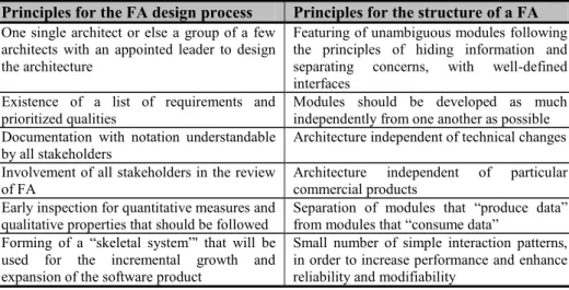
a product is reflected in the elegancy of its architecture. A look at well known software products that have met huge commercial success over the years, such as the Google search engine, SAP R3 or Linux OS, gives us an insight that a robust and well designed architecture constitutes a significant factor for the development, maintenance, usability and performance of a software product. A good functional architecture enables the usability of a software system, and should be able to survive many releases, so that new functionalities can easily be incorporated without making fundamental changes. These observations lead us to the search of structures that will enable the design of a high-quality functional architecture. Bass et al. [4] suggest that there is no scientific evidence to decide whether an architecture design is good or bad, but there are several rules that should be applied in the architecture design. In table 1, we mention their recommendations adjusted for the construction of a functional architecture.
Principles for the FA design process Principles for the structure of a FA
One single architect or else a group of a few architects with an appointed leader to design the architecture
Featuring of unambiguous modules following the principles of hiding information and separating concerns, with well-defined interfaces
Existence of a list of requirements and
prioritized qualities Modules should be developed as much independently from one another as possible Documentation with notation understandable
by all stakeholders Architecture independent of technical changes Involvement of all stakeholders in the review
of FA Architecture commercial products independent of particular Early inspection for quantitative measures and
qualitative properties that should be followed
Separation of modules that “produce data” from modules that “consume data”
Forming of a “skeletal system”' that will be used for the incremental growth and expansion of the software product
Small number of simple interaction patterns, in order to increase performance and enhance reliability and modifiability
Table 1. Font sizes of headings. Table captions should always be positioned above the tables.
The design of a functional architecture is influenced by four main factors[4]: First of all the requirements set by the stakeholders, functional and non-functional, determine what kind of functionalities are going to be incorporated, as also technical restrictions that have to be taken under consideration. Secondly, the developing organization affects the architecture, with regard to earlier versions of the product, or available design patterns to be used, or already known data such as an existing database, etc. But also the customer organization has a strong opinion in the division of functionalities, since they might also be affected by the architectural decisions later on. Furthermore, the technical environment, which includes software engineering techniques or industry standards available, available design tools and development platform, can influence the architectural decisions. Finally, the background and expertise of the architect influence the selection of architectural techniques to be followed.
Based on the aforementioned principles and the influences on architecture, we distinct three design structures for the functional architecture:
Modularity: According to Anderson [1], modular design is “a design technique in which functions are designed in modules that can be combined in subsequent designs”. Modularity is related to the decomposition of the software products in several components, their positioning in the system and their connectivity. Modularity in functional architecture has to be given a robust structure, so that each module incorporates a well-defined functionality and can be developed independent of other modules [19]. Flexibility is also an important aspect of modularity, in the sense that the structure should not change often in subsequent releases of the product, but should easily direct new requirements to its current modules or a new functionality in a new module.
Variability deals with the fact that the product might need to run in different organizational settings and cooperate with multiple products. Consequently, variability is related to the extent to which the various components can differ. Functional variability includes the product's modules that need to interact with different functional components; for example an ERP system used in multiple customer organizations might interact with different products in each organization. We also recognize technical variability, in the sense that technical features may need to differ on different platforms.
Interoperability defines the interfaces that need to be placed between the product's features and external products. The product should have interfaces adapted to the specifications of external products in order to enable interaction with them. Care should be taken to design standard interfaces for optimal flexibility [1]. Furthermore, the decision of positioning these interfaces in the software product needs to be taken within the interoperability structure.
In the following section, we elaborate the presented design principles and structures in our suggested approach for modeling the Functional Architecture.
3 Modeling the Functional Architecture of Software Products
The purpose of this paper is to emphasize the need for a uniform technique to model the Functional Architecture of Software Products. In this section we present the concepts related to Functional Architecture and we propose the Functional Architecture Model and its corresponding views, which are designed through the Functional Architecture Diagrams. In the second part of the section, we elaborate on the modular decomposition of the Functional Architecture.3.1 Functional Architecture Model
As we mentioned earlier, the Functional Architecture reflects a software product's architecture from a usage perspective. Evidently, such a model should resemble the functions performed in the individual user context, or −when we have to do with a corporate customer− the enterprise functions of the customer organization that are supported by the software product.
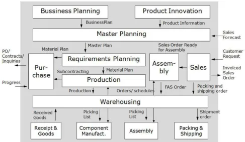
In figure 1 we can see an example of the functional architecture of Baan ERP Product [5]. Following the principle of modularity, each module in the FA represents a function in the customer domain (e.g. Requirement Planning, Production, etc). The flows represent interactions between functions or with external products. The principle of variability is also reflected in the functional architecture of the ERP Product, as it should easily run in different operating systems and platforms (technical variability) and in different customer organizations (functional variability). Finally, the interactions with other products or with the user indicate the interfaces that need to be built so that the product can interoperate with external factors.
Fig. 1. Functional Architecture of an ERP product
We define the Functional Architecture Model (FAM) as the representation of the primary functionality of a software product, consisting of its main functions and supportive operations. The purpose of designing the FAM is to identify the main functionalities performed by the software product; show the interactions of these functions between each other and with external products; and create a clear overview of how the product should operate in order to satisfy the user's requirements.
In order to model the FA of a software product we borrow the notation and rules of Enterprise Function Diagrams, which are used in the domain of Enterprise Architecture to model the primary process of an enterprise, its physical and administrative functions [15]. Consequently, a Functional Architecture Diagram (FAD) will contain modules that resemble the functions of a software product. A
function is defined as a collection of coherent processes, continuously performed within a software system and supporting its use. Functions are implemented in a software product by modules. The interactions between modules are represented in the function diagrams by flows.
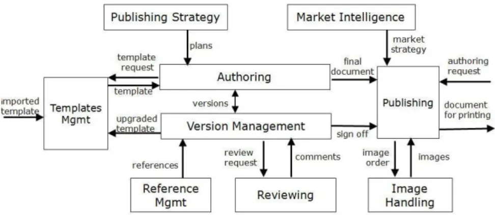
In figure 2, we can see the FAD of a collaborative authoring tool. This diagram visualizes the product's usage context, and could be useful for the phase of product roadmapping [26] as it indicates which modules need to be developed for each functionality of the product, thus the management can plan the development of the
product releases. Furthermore, such a diagram could be useful for modeling domain components of the software product in the context of core assets development in the software product line [17].
Fig. 2. Usage Context for a Collaborative Authoring Tool
For instance, supposing that the functions of Publishing Strategy, Market Intelligence, Reference Management, Reviewing and Image Handling are left out of the first release, we can see the product usage scope of the collaborative authoring tool in figure 3. The boxes (Authoring, Version Management, Templates Management, Publishing, etc) are called modules, and correspond to the software product parts that implement the respective functions. In the diagram, we can also see how the modules interact with each other through information flows, by sending and receiving requests, documents etc. An interface needs to be implemented in a module, for each information flow with other modules or external products.
Fig. 3. Product scope
3.2 Modular decomposition
The Functional Architecture of a software product is not limited in the product scope level. Instead, it can be modeled in more layers, supporting the functional
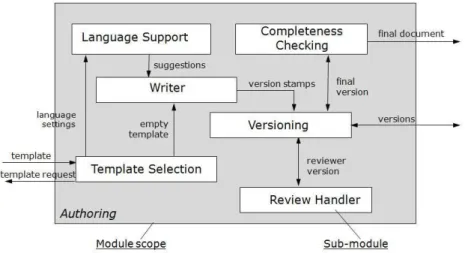
decomposition of the product. A module of the software product represents a set of sub-modules which correspond to lower level functions that interoperate to implement the corresponding functionality. On a second FA layer, we could consequently model the functional architecture on the module level. In figure 4 we can see the FAD that visualizes the module scope for the function Authoring. We strongly encourage preserving the consistency between FADs on different levels. For example, in figure 4 we can notice the same external interactions for the module Authoring, as the internal flows between this module and other modules in the FAD of the product scope in figure 3.
Fig. 4. FAD of the module Authoring
From our experience, we have noticed that the functional architecture is usually modeled in two to three layers. The FADs are designed following the same notation and rules, which we will see in the next section. On the lowest level, each module is supported by features, which represent the processes that constitute the respective function that the module implements. We remind here that functions were defined as collections of processes. A process is defined as an activity, the start and end of which are clearly defined and its execution can be described in terms of needed and delivered data. The features indicate what the software system does and not how it realizes it. They include lower level of details than the module.
The names of features usually start with a verb, to indicate the process they correspond to. Examples are: “open template”, “send template to”, “select rules”, etc. Processes are modeled by Feature Models, which constitute a modeling tool for the process support functionality in a software product. Riebisch [21] has elaborated on defining feature models for supporting processes in software product lines. The feature models are considered as a criterion for ending the modular decomposition of the functional architecture, as we know that by reaching the process level we have created a sufficient number of views of the functional architecture model.
In this section we presented the Functional Architecture Model, which is reflected in the different views, visualized by Functional Architecture Diagrams, on different layers of decomposition. In the next section we will suggest a technique for creating the FAM in simple and uniform diagrams, applicable for any product domain.
4 An Approach for Designing Functional Architecture Diagrams
We now propose a technique for modeling the Functional Architecture of software products; we introduce a notation and some conventions for designing the FADs presented in the previous section; we suggest a series of easy steps for the design; and we illustrate our approach through an example.4.1 Notation and Conventions for Functional Architecture Diagrams
One of our goals is to have a very simple notation so that functional architecture can easily be communicated with stakeholders with no specialization on software architecture, such as the customers of the software vendor. The notation of a FAD can be seen in figures 3 and 4. The following constructs are used:
a) We use boxes to model modules or sub-modules of the product, which represent functions or processes. For the naming we use substantivized nouns (e.g. Planning instead of Plan), which need to start with capital letter. The choice of names is critical: since the diagram will constitute a fundamental means of communication amongst the stakeholders, precise and determining terms that are well known in the business domain are preferred. Finally, coloring can be used to categorize the modules hierarchically or according to their use.
b) Arrows are used to model interactions between modules in the form of
information flows. Typical examples of information flows include notifications, requests, feedback to requests, and documents. The names of information flows are all written in lower case.
c) A rectangle is used to cover the modules of the product (or the sub-modules of the modules) to indicate the product (or module) scope. The module name should be stated in the lower-right corner of the rectangle.
It is a convention to position the modules hierarchically in the FADs. Vertically, we position the modules according to their control, i.e. in a hierarchical order, from high to low:
Strategic modules, which implement management related functions, such as Business Planning, Product Innovation.
Tactical modules, which are related to control items, e.g. Requirements Planning. Operational modules, which have to do with execution functions, such as
Production, Assembly.
Supportive modules, which are related to platform issues, e.g. Warehousing. Horizontally, we position the modules from left to right according to the flow of execution:
Modules that implement input functions (e.g. Purchase) are positioned on the left side.
Modules related to processing functions (e.g. Production, Assembly) are placed in the middle.
Modules related to output functions (e.g. Sales) are positioned on the right side of the diagram.
Third party products are positioned outside the product scope: External products that provide input to the product's modules are placed on the left side, while external products that receive the output of the product's modules are placed on the right side.
4.2 Creating a Functional Architecture Diagram
In this section we present the basic steps for modeling the Functional Architecture of a software product with a functional architecture diagram. We illustrate the process with the example of a Dining Room Management Application. The usage context of the product consists of all the functions that need to be performed in a restaurant, from the handling of a reservation, the processing of an order, up to the customer's payment.
Determine the scope
At first, we need to decide upon the product scope: the scope constitutes the functionalities of the software product. All external products in the usage environment need to be identified, with which the product will interact. Furthermore, products with which the product will possibly be interfaced in the future need to be defined at this stage. The Product Context Diagram [6] can be a starting point for identifying the third party applications that will interact with the software product.
For example, if we are architecting a software application for dining room management in restaurants, the external products would be a labor management application, the ERP system of the restaurant, a book keeping application, and possibly in the future it could also interface with an e-commerce application for restaurant reservations (figure 5a).
Define request-feedback flows
After determining the scope, we need to define the functional interactions between the modules of the product and the external products. Most of the times, the interactions appear in a pair of a request flow and a return arrow that represents the feedback of the result. This construction is called a request feedback loop. We focus on the main interactions that are related to the primary functionality of the product.
Referring to the restaurant application example, the defined request-feedback loops between the product and the third party applications are defined in figure 5b.
(a) Product Scope and external products (b) Request-feedback flows with external applications Fig. 5. Steps i and ii
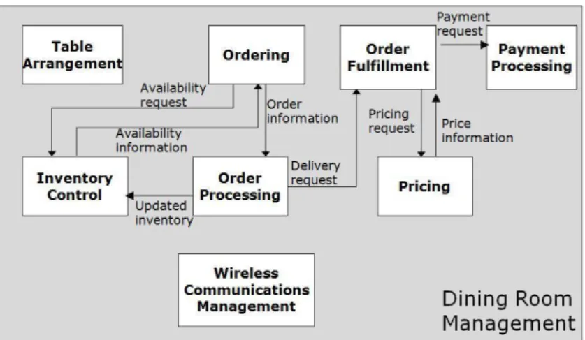
Model the operational module flow
The next step consists in modeling the operational module flow, i.e. the flow of the modules that constitute the implementation of the main functionality of the product. The operational module flow usually shows the input, the primary process and the output. We identify the steps as module boxes, which are separated by flows that are usually information flows or waiting queues.
Figure 6 includes the operational modules that are needed for the Dining Room Management application. The Table Arrangement module includes the related processes for finding an available table for a new customer request. The Ordering module consists of the processes related to a customer's meals order. The module Order Processing corresponds to the processing of orders in the kitchen and updating the status of each order. The Inventory Control module contains the processes of checking whether there is enough inventory for preparing a meal and thus realizing the corresponding order. The Order Fulfillment box refers to the functionalities of arranging the processed orders and delivering them to the tables. The Pricing module is related to arranging the menu prices. Finally, the Payment Processing module corresponds to arranging a payment method, executing the payment and printing the invoice. Apart from these operating modules, we can also see in the diagram the supportive module Wireless Communications Management, which ensures that all wireless communications between the PDAs and the central component are functioning correctly. For reasons of readability we have not added the flows of the supportive module, which needs to interact with all the operating modules.
Fig. 6. The operational modules
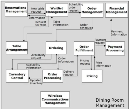
Add control and monitoring modules
Usually, the operational module flow is controlled by one or more control modules, which in turn are controlled by planning modules. We add the control module that corresponds to each operational module. The interaction between an operational and a
control module is a request-feedback loop. On top of the control modules, we add the appropriate planning modules.
In our restaurant application example we can only identify control modules, which are added in the diagram. The module Reservations Management is handling the reservations request, while the waitlist management arranges all requests that are queued, either from new reservations or from new customers that have visited the restaurant directly. The Order Management module schedules and prioritizes the handling of orders. Finally, the Financial Management module corresponds to the financial management processes, e.g. registering payments, storing the invoices, etc.
Fig. 7. Adding control and monitoring modules in the Dining Room Management application
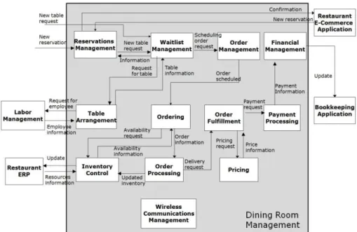
Specify external to/from internal interactions
This step is related to the second step, where we had to identify the interactions between the product and external products. At this point we need to perform further analysis, to identify which of the modules will need to be interfaced with the external product for each request-feedback flow. It is possible that we may discover new modules at this stage which we had ignored in the previous steps. Also, for the sake of certain interaction we may need to add more interactions also amongst the internal modules of the product.
In figure 8 we can see the final FAD of the Dining Room Management application. All interactions from the external third party applications to the product's modules and vice versa are modeled in this step. The functions are triggered either by
a new table request, which corresponds to a request of a customer who visits the restaurant without reservation, or by a new reservation request, which can be performed either by a customer directly or through a related e-commerce application.
Fig. 8. The complete FAD of the Dining Room Management application
5 Discussion and Conclusions
In this paper, we accentuated the need for modeling the Functional Architecture of software products. We proposed the Functional Architecture Model which can be visualized through Functional Architecture Diagrams in different layers of decomposition. We provided a technique for creating FADs and in parallel illustrated the design process through an example.
The Functional Architecture Model has been introduced in a manner that supports the design principles and structures for FA discussed in section 2. As far as the principles for the FA design process are concerned: The FA can be designed by one or few architects, based on the existing requirements and prioritized qualities, which can easily be mapped on the product's modules. The notation is easily understandable by non-specialists, thus all stakeholders (product managers, architects, developers, customers, marketing and sales, end-users) can be involved in the review of FA. The visualization of FA through FADs eases the identification of bottlenecks and the inspection of qualitative and quantitative measures. Finally, the suggested modular decomposition supports the creation of a “skeletal system” that can easily be expanded in the future by adding new modules.
Regarding the principles for the structure of FA, first of all the modules in our FAM separate concerns and support the hiding of information, while the interfaces are placed only when request-feedback flows between modules and/or external products are needed. Evidently, since each module corresponds to different functionality, it is possible to develop modules quite independently from one another, while the focus on functionalities makes the architecture independent of technical changes and of particular commercial products, and enables the introduction of few and simple interaction patterns that increase performance and enhance modifiability and reliability. The suggested convention of positioning the modules hierarchically and according to the flow of execution separates the modules that “produce data” from those that “consume data”.
The suggested design structures for the FA were followed in our FAM approach. Modularity is supported by the creation of modules which correspond to different product functionalities and are later on decomposed in lower levels of abstraction. In section 3, we inspected the modules of the product scope for a Collaborative Authoring Tool and the decomposition of its “Authoring” module into sub-modules. The FADs are structured in a way that the FA can easily be adapted in different organizational settings. For example, the FAD for a Dining Room Management application in figure 8 was constructed for a restaurant environment. However, it could easily be adapted in other similar environments: certain modules (Ordering, Inventory Control, Order Processing, Pricing, Payment Processing, Financial Management) are standard for all organizational settings while the remaining modules are variant according to the environment. If we wanted to create the FAD for a fast food restaurant, we could simply remove the modules Reservations Management, Waitlist Management, Order Management and Table Arrangement and insert the module Order Forecasting. Finally, the inspection of the request-feedback flows enables the identification of all possible interfaces that will need to be designed so that the product can flexibly interact with different external products, confirming the interoperability structure.
The Functional Architecture Model can facilitate the system design by describing the inherent functional structure of the system's modules and their interactions, as well as the interactions with external applications. The modular decomposition offers a separation of the system's functionalities, thus it reduces complexity, eases the communication and collaboration among stakeholders, enables managing the product development by partitioning work into independent tasks, and set off transferrable and reusable elements of the product.
We suggest that FADs constitute a powerful tool for modeling the functional architecture of software products. The notation is rather simple thus they can easily and quickly be designed, leaving space to the architect to deal with planning the functionalities of the product in an optimal way and easing the communication with the non-specialist customers, who can recognize the models without formal training.
FADs can be used to determine the modules of the software product. Although certain programming languages like Java support hierarchical module structure, other languages (e.g. PHP) have not developed modularity sufficiently. A module structure is critically essential for designing a software product, in order to plan and organize the development work [19].
Moreover, FADs indicate the interactions between the product's modules and the environment. This is convenient from a development point of view, since we have a visualization of which interfaces will need to be implemented for the software product, as also from a management point of view, to have an indication of which third party products will interact with the software product.
Finally, our proposed approach for Functional Architecture Modeling can be applied in any type of business: public sector (healthcare, governmental) and private sector (manufacturing, financial, services, food and beverage, project industries).
In our future research we intend to inspect the incorporation of scenarios with the functional architecture diagrams, in order to visualize on a high level the flow between the product's modules and third party applications for the implementation of the system's functionalities.
References
1. Anderson, D.M.: Design for Manufacturability. Optimizing Cost, Quality and Time-to-Market. CIM Press, Cambria, CA (2001)
2. Angelov, S., Grefen, P.W.P.J., Greefhorst, D.: A classifcation of software reference architectures: Analyzing their success and effectiveness. In: Proceedings Joint Working IEEE/IFIP Conference on Software Architecture & European Conference on Software Architecture 2009. (2009) 141–150
3. Arsanjani, A., Zhang, L.J., Ellis, M., Allam, A., Channabasavaiah, K.: Design an SOA solution using a reference architecture. (2007) From
http://www.ibm.com/developerworks/library/ar-archtemp/
4. Bass, L., Clements, P., Kazman, R.: Software architecture in practice. Addison-Wesley Longman Publishing Co., Inc., Boston, MA, USA (1998)
5. Brinkkemper, S.: Dynamic enterprise innovation: Establishing continuous improvement in business. In R. van Es (eds.) pp. 4–15. Baan Business Innovation.(1998)
6. Brinkkemper, S., Soest, I. van & Jansen, R.L.: Modeling of product software businesses: Investigation into industry product and channel typologies. In proceedings of the Sixteenth International Conference on Information Systems Development (ISD 2007). Springer-Verlag.(2007)
7. Broy, M., Gleirscher, M., Merenda, S., Wild, D., Kluge, P., Krenzer, W.: Toward a holistic and standardized automotive architecture description. Computer 42 (2009) 98–101
8. Buckl, S., Ernst, A.M., Matthes, F., Ramacher, R., Schweda, C.M.: Using enterprise architecture management patterns to complement TOGAF. In: EDOC’09: Proceedings of the 13th IEEE international conference on Enterprise Distributed Object Computing, Piscataway, NJ, USA, IEEE Press (2009) 32–39
9. Fowler, M.: Who needs an architect? IEEE Softw. 20(5) (2003) 11–13
10. van Gurp, J., Brinkkemper, S., Bosch, J.: Design preservation over subsequent releases of a software product: a case study of baan erp: Practice articles. J. Softw.Maint. Evol. 17(4) (2005) 277–306
11. Herzum, P., Sims, O.: Business Components Factory: A Comprehensive Overview of Component-Based Development for the Enterprise. JohnWiley & Sons, Inc.,New York, NY, USA (2000)
12. IBM Insurance Application Architecture,
13. Ieee std 1471–2000, recommended practice for architectural description of software-intensive systems. Technical report, IEEE (2000)
14. Koning, H.: Communication of IT Architecture. Thesis Dutch Research School for Information and Knowledge Systems. (2008)
http://igitur-archive.library.uu.nl/dissertations/2008-0908-200828/koning.pdf
15. Koning, H., Bos, R., Brinkkemper, S.: A lightweight method for the modeling of enterprise architectures. In: Service-Oriented Computing – ICSOC 2008 Workshops: ICSOC 2008 International Workshops, Sydney, Australia, December 1st, 2008, Revised Selected Papers, Berlin, Heidelberg, Springer-Verlag (2008) 375–387
16. Kruchten, P.: The 4+1 view model of architecture. IEEE Softw. 12(6) (1995) 42–50 17. Moon, M., Yeom, K.: An Approach To Developing Core Assets in Product Line,
Asia-Pacific Software Engineering Conference, pp. 586-588, In: 11th Asia-Asia-Pacific Software Engineering Conference (APSEC’04), 586-588 (2004)
18. Nab, J., Pilot, A., Brinkkemper, S., Berge, H. ten.: Authentic competence-based learning in university education in entrepreneurship. International Journal of Entrepreneurship and Small Business. 9(1) (2010) 20 – 35.
19. Parnas, D.L.: On the criteria to be used in decomposing systems into modules. Commun. ACM 15(12) (1972) 1053–1058
20. Reed, P.: Reference Architecture: The best of best practices. (2002) http://www.ibm.com/developerworks/rational/library/2774.html
21. Riebisch, M.: Towards a more Precise Definition of Feature Models – Modelling Variability for Object-Oriented Product Lines. BookOnDemand Publ. Co., Norder-stedt. (2003) 64–76.
22. Soni, D., Nord, R.L., Hofmeister, C.: Software architecture in industrial applications. In: ICSE ’95: Proceedings of the 17th international conference on Software Engineering, New York, NY, USA, ACM (1995) 196–207
23. Supply Chain Council (2010). What is SCOR? Retrieved March 10, 2010, from http://www.supply-chain.org/about/scor/what/is
24. Software Engineering Institute.: How Do You Define Software Architecture? (2005) http://www.sei.cmu.edu/architecture/definitions.html
25. van Vliet, H.: Software engineering (2nd ed.): principles and practice. John Wiley & Sons, Inc., New York, NY, USA (2000)
26. van de Weerd, I., Brinkkemper, S., Nieuwenhuis, R., Versendaal, J., Bijlsma, L.: Towards a reference framework for software product management. In: IEEE International Conference on Requirements Engineering, Los Alamitos, CA, USA, IEEE Computer Society (2006) 319–322
27. Zachman, J.A.: A framework for information systems architecture. IBM Syst. J. 26(3) (1987) 276–292