An energy-centric handover decision algorithm for the integrated
LTE macrocell–femtocell network
Dionysis Xenakis
a, Nikos Passas
a,⇑, Christos Verikoukis
b aDepartment of Informatics and Telecommunications, University of Athens, 15784 Athens, Greece b
Telecommunications Technological Centre of Catalonia, Barcelona, Spain
a r t i c l e
i n f o
Article history: Available online xxxx Keywords: Femtocells LTE Mobility management Handover decision Energy-efficiencya b s t r a c t
Femtocells are attracting a fast increasing interest nowadays, as a promising solution to improve indoor coverage and system capacity. Due to the short transmit-receive distance, femtocells can greatly lower transmit power, prolong handset battery life, and enhance the user-perceived Quality of Service (QoS). On the other hand, technical challenges still remain, mainly including interference mitigation, security and mobility management, intercepting wide deployment and adoption by both mobile operators and end users. This paper introduces a novel energy-centric handover decision policy and its accompanied algorithm, towards minimizing the power consumption at the mobile terminal side in the integrated LTE macrocell–femtocell network. The proposed policy is shown to extend the widely-adopted strongest cell policy, by suitably adapting the handover hysteresis margin in accordance with standardized LTE measurements on the tagged user’s neighbor cells. Performance evaluation results show that significantly lower interference and power consumption can be attained for the cost of a moderately increased num-ber of network-wide handover executions events.
Ó2012 Published by Elsevier B.V.
1. Introduction
The ever-increasing demand for higher data rates and improved indoor coverage has motivated the standardization and implemen-tation of short-range, low-cost, consumer-deployed cellular access points, referred to as femtocells[1]. Femtocells interconnect stan-dard mobile devices to the mobile operator’s network via the end user’s broadband access backhaul, e.g., a Digital Subscriber Line (DSL). Femtocells embody the functionality of a regular cellular station, operating in the mobile operator’s licensed band, and sup-porting up to a relatively small number of users (e.g., four users
[2]). From the mobile operator perspective, femtocell deployment (a) reduces the capital and operational costs, i.e. femtocells are deployed and managed by the end user, (b) improves the licensed spectrum spatial reuse and (c) decongests nearby macrocell base stations. On the other hand, the end users perceive (a) enhanced indoor coverage, (b) improved Quality of Service (QoS) and (c) sig-nificant User Equipment (UE) energy savings.
The Release 9 series of standards for the 3rd Generation Partnership Project (3GPP) the Long Term Evolution (LTE) system
[3]is one of the first standards to provision the deployment of fem-tocells. In the context of LTE, a macrocell is referred to as evolved Node B (eNB), while a femtocell is referred to as Home eNB (HeNB).
A LTE user is considered part of a Closed Subscriber Group (CSG) if it is permitted to utilize a particular set of closed access femtocells or if it receives prioritized service on a particular set of hybrid ac-cess femtocells [4]. The standard includes the cell identification and access control procedures in the presence of LTE femtocells, along with the mobility management procedure for CSG femto-cells. Ongoing work takes place towards the mobility management procedure for hybrid access femtocells, while the open access mode is out of the standard’s scope at the time of writing [4]. The detailed network architecture and mobility management pro-cedures in LTE can be found in[3].
Mobility Management (MM) is considered as one of the most challenging issues in the integrated LTE macrocell - femtocell net-work, both due to the high femtocell density within a macrocell, and the fact that femtocells are installed and managed by the end user [1]. Current literature includes various handover (HO) decision algorithms [5–9], mainly focusing on minimizing the number of network-wide HOs due to the femtocell sensitiveness on user mobility. Two different sets of speed and Received Signal Strength (RSS) based HO rules are proposed in [5], to minimize the HO probability in a two-tier macrocell - femtocell network. The proposed rules are shown to increase the user-perceived throughput in high speed UE and reduce the HO probability com-pared to a soft HO approach. The authors in[6]identify two HO strategies in the presence of femtocells, (a) the proactive strategy, where the strongest cell HO decision policy is employed[7], and
0140-3664/$ - see front matterÓ2012 Published by Elsevier B.V.
http://dx.doi.org/10.1016/j.comcom.2012.04.024
⇑ Corresponding author. Tel.: +30 2107275651; fax: +30 2107275601. E-mail addresses:[email protected](N. Passas),[email protected](C. Verikoukis).
Contents lists available atSciVerse ScienceDirect
Computer Communications
j o u r n a l h o m e p a g e : w w w . e l s e v i e r . c o m / l o c a t e / c o m c o m
(b) the reactive strategy, where a femtocell outband HO is executed only when the minimum required RSS for service continuity is reached. The reactive strategy is adopted when the user traffic is real-time, while the proactive is preferred when the user traffic is non-real time. Although preliminary results show that the pro-posed scheme reduces the overall number of HOs in the system, the user-perceived throughput degradation and the consequential interference on the ambient Radio Frequency (RF) environment are not investigated. An adaptive HO Hysteresis Margin (HHM) ap-proach is presented in[8], where the HHM value is adapted accord-ing to the distance between the UE and the target cell, estimated from RSS and Signal to Interference and Noise Ratio (SINR) mea-surements on the UE. It is shown that a large HHM mitigates the unnecessary HOs although it simultaneously results to user-per-ceived throughput degradation. Assuming known user speed, the proposal in[9]allows for a HO towards a nearby femtocell either if the user speed is lower than 15 km/h or if the user speed is up to 30 km/h and the user traffic is real-time. For the macrocell to macrocell and the femtocell to femtocell HO decision scenario, the proposed algorithm decides on a HO with respect to a mixed metric that includes the RSS, the maximal capacity, and the num-ber of UEs camped on the target cells. The optimization of the pro-posed metric and the acquisition of the required HO decision parameters at the serving LTE cell, however, are not thoroughly investigated.
The main focus in existing LTE HO decision algorithms is given in prioritizing femtocells over macrocells in accordance with user mobility criteria. Nevertheless, the strongest cell HO decision pol-icy[10]is typically considered for both macro-macro and femto-femto HO scenarios. According to it, the serving cell proceeds to a HO execution whenever the Reference Signal Received Power (RSRP)[3]of a neighbor cell exceeds over the respective RSRP sta-tus of the serving cell plus a policy-defined HHM, for a policy-de-fined time period namely the Time To Trigger (TTT). The HHM is typically introduced to mitigate UE measurement inconsistencies, encompass frequency-related propagation divergences and mini-mize the ping-pong effect [10], i.e. consecutive HOs originating from the user movement across the cell boundaries. If comparable downlink Reference Signal (RS) power transmissions are assumed amongst the LTE cells, the strongest cell HO policy facilitates mobility towards a LTE cell with preferential propagation charac-teristics. However, this is not the case of the integrated LTE macro-cell–femtocell network where femtocells are expected to radiate comparably lower downlink RS power for interference mitigation on the macrocell layer[1]. Divergent RS power transmissions are expected even amongst the femtocell layer, in accordance with the adopted self-optimization procedure[11]. Apart from RS power transmission divergences, substantial RF interference divergences are also expected amongst the LTE cells. RF interference is an inev-itable product of the unplanned femtocell deployment, both in terms of location and operating frequency, even if advanced inter-ference cancellation and avoidance techniques are adopted [1– 2,12–15]. The RF interference divergences amongst the LTE cells may severely deteriorate the user-perceived QoS due to service outage and substantially increase the network signaling due to mobility, if the interference-agnostic strongest cell HO decision policy is adopted.
On the other hand, a noteworthy amount of studies conclude that the femtocell technology is one of the most promising energy efficiency enablers. The study in[16]indicates that compared to a standard macrocell deployment, femtocell deployments may sig-nificantly reduce the energy consumption on both the access net-work and the mobile terminals from four to eight orders of magnitude. Analogous results are derived in terms of system capac-ity per energy unit, although the performance degradation due to increased RF interference between the macro – femto and the femto
– femto systems is not investigated. The latter effect is incorporated in[17], where it is shown that in-band macro – femto coexistence results in non-negligible performance degradation on the macrocell network layer. Nevertheless, improved QoS and significantly re-duced energy consumption per bit are simultaneously achieved in the UE, with respect to the femtocell deployment density. To fur-ther reduce the energy consumption on the femtocell access point (FAP), the authors in[11]propose an idle mode procedure accord-ing to which the pilot transmissions are disabled in the absence of nearby cellular user activity. Compared to static pilot transmis-sion, the proposed procedure is shown to significantly reduce the overall signaling overhead due to mobility. However, further work is required to investigate the impact of pilot transmission disabling during the cell search and measurement phase.
In conclusion, apart from improved indoor coverage and en-hanced user-perceived QoS, femtocells natively achieve significant energy savings at both the access network and the UE side. To this end, more sophisticated HO decision algorithms are required in the presence of LTE femtocells to fully exploit the native femtocell superiority both in terms of enhanced QoS and reduced energy consumption. This paper introduces a novel energy-centric HO decision policy, referred to asUE Power Consumption Minimization
(UPCM) policy, incorporating standardized LTE context towards minimizing the UE power consumption while maintaining QoS. The UPCM policy enhances the strongest cell HO policy by intro-ducing an adaptive HHM according to standardized UE and LTE cell measurements. The acquisition of these measurements on the LTE serving cell is thoroughly investigated in terms of required net-work signaling and enhancements. An enhanced HO decision algo-rithm is subsequently proposed, to resourcefully employ the proposed UPCM policy while mitigating unnecessary HO execution events.
The remainder of this paper is organized as follows. Section 2 includes the adopted system model, discusses the predominant strongest cell HO decision policy and introduces the proposed UPCM policy. Based on this policy, a novel HO decision algorithm is described in section 3 along with the required network signaling and enhancements. Section 4 includes selected numerical results, revealing the effectiveness of the proposed HO decision algorithm both in terms of energy conservation and interference mitigation. Finally, section 5 concludes the paper.
2. UE power consumption minimization ho decision policy The integrated LTE macrocell–femtocell network is considered, operating in a spectrum pool divided intoNbands. The communica-tions in band n
e
N = {1,. . .,N} are carried out in a time frame basis, according to the Orthogonal Frequency Division Multiplexing (OFDM) scheme[3]. Each timeframe may utilize up toRnResourceBlocks (RB) from the RB setRn= {1,. . .,Rn}, where each RB consists
of a consecutive number of OFDM symbols located on a consecutive number of OFDM subcarriers[18]. LetCndenote the LTE cell set
operating in bandn2N, including both macrocells and femtocells, andUn the LTE user set receiving service from cellc2Cn. For a
tagged cellc2Cn, let Rc,DL =r1c;rcRc;DL and Rc,UL =r c
1;rcRc;UL denote
the utilized RB sets in the downlink and uplink directions respec-tively, whereRc;DL;Rc;UL#Rn. Moreover, let pcn¼ ½pc1pc2 pcRn and
pc
n¼ ½pc1pc2 pcRn denote the downlink and uplink transmission
power vectors of cellc2Cn and useru2Unrespectively, where
pc
r¼0;8r2RnRc;DL and pur ¼0;8r2RnRc;UL. For a tagged RB
r2Rn, let
r
2r denote the noise power,h u!cr the channel gain from
useru2Sn2NUnto cell c2Sn2NCn and hcr!u the channel gain in
the reverse direction. In a similar manner, lethur0!udenote the
chan-nel gain from useru0to useruandhc0!c
r the channel gain from cellc0
to cellc, whereu;u02U
n andc;c02Cn. Then, the corresponding Please cite this article in press as: D. Xenakis et al., An energy-centric handover decision algorithm for the integrated LTE macrocell–femtocell network,
downlink and uplink SINR on service reception are given in(2.1) and (2.2), respectively.
c
c!u r ¼ pc rh c!u r P c02Cncpc 0 r h c0!u r þ P u02Unupu 0 r h u0!u r þr
2r ;8
r2Rc;DL#Rn ð2:1Þc
u!c r ¼ pu rh u!c r P c02Cncpc 0 r h c0!u r þ P u02Unupu 0 r h u0!c r þr
2r ;8
r2Rc;UL#Rn ð2:2ÞIt results that to accurately estimate the expected SINR on a tar-get LTE cell, the entire parameter set in(2.1) and (2.2)is required. However this is infeasible in practice, provided that the conse-quential SINR strongly depends on the imminent RB allocation on the target LTE cell, which cannot be a priori known. To this end, the mobility decision in LTE is performed according to UE signal qual-ity measurements on the target LTE cell’s downlink RS[18]. Signal quality measurements can also be derived by each LTE cell, within its operating bandwidth, to further enhance the mobility decision in LTE.Table 1summarizes some of the basic UE and LTE cell mea-surement capabilities [19], while it additionally includes the adopted paper notation for a tagged LTE useru2Unand cellc2Cn.
In the following, it is considered that useru2Unprovides its
servingcells2Cnwith consistent RSRP and RSRQ measurements
on an accessible neighbor cell setLu#Sn2NCn, identified during
the LTE cell search and measurement phase. The particular proce-dure where an accessible neighbor cell setLuis identified and
con-sistent RSRP and RSRQ measurements are derived, is out of the scope of this paper, i.e. both network-configured and UE-based procedures are allowed. To the remainder of this section, subsec-tion 2.1 models the widely-adopted strongest cell HO policy in the context of the integrated LTE network, while subsection 2.2 introduces UPCM, a novel HO policy incorporating standardized LTE UE and network measurements towards minimizing the UE power consumption.
2.1. Strongest cell handover decision policy
Considering that the RSRP and RSRQ measurements are reported only upon LTE critical events lasting for at least the TTT
period[20], the strongest cell HO policy can be described as fol-lows. The serving eNB decides on a HO whenever the reported RSRP status of a neighbor eNB exceeds over the respective RSRP status of the serving eNB plus a policy-defined HHM. Thus, the strongest cell criterion in LTE is described as in (2.1.1), where
HMc,(dB)is a network-configured cell-specific HHM introduced for
mitigating UE measurement inconsistencies, frequency-related propagation divergences and user mobility originating side-effects.
argmaxc2LuRSRP c!u ðdBÞ :¼ fcjRSRP c!u ðdBÞ>RSRP s!u ðdBÞþHMc;ðdBÞg ð2:1:1Þ Let Pcr;RS denote the respective RS power transmission in RB
r2Rc;DL. Then, by the RSRP definition:
RSRPc!u¼ P r2Rc;DLP c r;RSh c!u r Rc;DL ð2:1:2Þ By substitutingPc
r;RSwith the average downlink RS power
trans-missionPcRSin cellc: RSRPc!u ¼Pc RS P r2Rc;DLh c!u r Rc;DL ) RSRPc!u ðdBÞ¼P c RS;ðdBÞþh c!u RS;ðdBÞ ð2:1:3Þ ,wherehc!u RS ¼ P r2Rc;DL hc!u r
Rc;DLcorresponds to the linear average over the
channel gain contributions of all RBs within the operating band-width of cell c. Thus, the strongest cell HO decision criterion in LTE can be rearranged as follows:
arg maxc2LuðPcRS;ðdBÞþh c!u RS;ðdBÞÞ:¼ fcjP c RS;ðdBÞþh c!u RS;ðdBÞ >PsRS;ðdBÞþh s!u RS;ðdBÞþHMc;ðdBÞg ð2:1:4Þ It results that when comparable RS power transmissions are as-sumed amongst the LTE cells, the strongest cell HO decision policy facilitates mobility towards a LTE cell with preferential propaga-tion characteristics. However, this is not the case of the integrated LTE macrocell–femtocell network, where substantial RF interfer-ence and downlink RS power transmissions diverginterfer-ences are ex-pected amongst the cells. To this end, a novel HO decision policy is described in the following, to enhance the HO decision phase in the presence of LTE femtocells.
Table 1
LTE UE and cell link quality measurements.
Measurement Definition Performed
by
Notation Reference signal received power
(RSRP)
The linear average over the power contributions (in [W]) of the resource elements that carry cell-specific reference signals within the considered measurement frequency bandwidth. For RSRP determination the cell-specific reference signals R0 shall be used while if the UE may use R1 in addition to R0 if it is reliably detected. The reference point for the RSRP shall be the antenna connector of the UE
UE RSRPc?u
E-UTRA Carrier Received Signal Strength Indicator (RSSI)
The linear average of the total received power (in [W]) observed only in OFDM symbols containing reference symbols for antenna port 0, over Rc,DLnumber of RBs by the UE from all sources, including co-channel serving and non-serving cells, adjacent channel interference, thermal noise etc. RSSI is not reported as a stand-alone measurement rather it is utilized for deriving RSRQ
UE RSSIc?u
Reference Signal Received Quality (RSRQ)
The ratio Rc,DLRSRP/(E-UTRA carrier RSSI) where Rc,DLis the number of RB’s of the E-UTRA carrier RSSI measurement bandwidth. The measurements in the numerator and denominator shall be made over the same set of RBs. The reference point for the RSRQ shall be the antenna connector of the UE
UE RSRQc?u
Downlink Reference Signal Transmitted Power (DL RS Tx)
The linear average over the power contributions (in [W]) of the resource elements that carry cell-specific reference signals which are transmitted by a tagged cell within its operating system bandwidth. For DL RS TX power determination the cell-specific reference signals R0 and if available R1 can be used. The reference point for the DL RS TX power measurement shall be the TX antenna connector
E-UTRAN Pc RS
Received Interference Power The uplink received interference power, including thermal noise, within one physical RB’s bandwidth ofNRB
sc resource. The reported value shall contain a set of Received Interference Powers
for all the uplink physical RBs. The reference point for the measurement shall be the RX antenna connector
E-UTRAN Ic¼ ½ic1 i
c Rc;UL
2.2. The proposed HO decision policy
The proposed UPCM policy is based on handing over to a neigh-bor cell that minimizes the expected UE power transmission, for a given SINR target. The following analysis is pursued to efficiently evaluate the expected uplink power transmission of a tagged user for every candidate LTE cell. Let
c
c!udenote the average downlinkSINR of a tagged useru2Sn2NUnon a target cellc2Sn2NCn. Then,
c
c!ucan be derived as the linear average over the SINRcontribu-tions on each downlink RB, within the operating bandwidth of the target cell:
c
c!u¼ P r2Rc;DLc
c!u r Rc;DL ¼ X r2Rc;DL pc rh c!u r Rc;DL Pc02Cncpc 0 r h c0!u r þ P u02Unupu 0 r h u0!u r þr
2r ;8
r2Rc;DL ð2:2:1ÞIn the context of LTE, the numerator in(2.2.1)can be evaluated by: pc rh c!u r ffiP c RSh c!u RS h c!u RS ¼RSRP c!u ð2:2:2Þ
while the denumerator by taking into account the RSSIc!u
definition: RSSIc!uffi Xpc0 r h c0!u r þ X pu0 r h u0!u r þ
r
2r ð2:2:3ÞAccordingly, the average downlink SINR for a target LTE cell can be evaluated as follows:
c
c!u¼ X r2Rc;DL RSRPc!u Rc;DLRSSIc!u ¼RSRP c!u RSSIc!u ¼RSRQ c!u ð2:2:4ÞOn the other hand, the respective average SINR in the LTE uplink is defined as:
c
u!c ¼ X r2Rc;UL pu rh u!c r Rc;UL X c02Cnc pc0 r h c0!u r þ X u02Unu pu0 r h u0!u r þr
2r !;8
r 2Rc;UL ð2:2:5ÞIn a similar manner, the denumerator in(2.2.5)can be derived by considering the Received Interference Power definition and that the tagged user’s uplink transmissions are included in the respec-tiveicrLTE measurement, when the serving and the target cell oper-ate in the same band:
X c02Cnc pc0 r h c0!c r þ X u02Unu pu0 r h u0!c r þ
r
2r ! ffi ðicrpurh u!c r Þ ð2:2:6ÞNote that if the current serving and the target LTE cell operate in different bands, the term pu
r
c
u!c is omitted. By incorporating (2.2.2) and assuming a symmetric channel gain between user uand cellc,hu!c
r can be derived as:
hur!cffih c!u r ffih c!u RS ¼ RSRPc!u Pc RS ð2:2:7Þ
Thus, for an average uplink powerPu!c
UL per RB the average SINR
in the LTE uplink is given as:
c
u!c¼Pu!c UL h c!u RS X r2Rc;UL 1 Rc;UL ði c rP u!s UL h u!c r Þ ð2:2:8ÞGiven an average uplink SINR target
c
ut, equation(2.2.8)can be
utilized for evaluating the average uplink power transmission per RB for both the tagged user’s serving(2.2.9) and neighbor cells
(2.2.10). This SINR target is strongly correlated to the native QoS characteristics of the ongoing user services, and it is thus consid-ered known in the serving LTE cell. For example, it can be com-puted based on the average rate requirements for sustaining the ongoing user services and a spectral efficiency to SINR threshold mapping such as the one provided in page 109 of[12].
Pu!s UL ¼
c
u t hsRS!u P r2Rs;UL 1 Rs;ULðis rÞ ð2:2:9Þ Pu!c UL ¼c
u t hsRS!u P r2Rs;UL 1 Rs;ULðicrPu!sUL h u!c r Þ ð2:2:10ÞTaking into account that the UE uplink transmissions dictate the power consumption in the UE[16],(2.2.10)can be utilized to iden-tify the LTE cell with the lower UE power consumption. Accord-ingly, a neighbor LTE cellc2Luis expected to result in lower UE
power consumption compared to the serving LTE cell s2Cn, if
and only if:
Pu!s UL >P u!c UL ) ð2:2:11Þ
c
u t hsRS!u P r2Rs;UL 1 Rs;ULisr >c
u t hcRS!u P r2Rs;UL 1 Rc;ULðicrPu!sUL h u!c r Þ ) ð2:2:12Þ hcRS!u X r2Rs;UL 1 Rc;UL ðicrP u!s UL h u!c r Þ ! hsRS!u X r2Rs;UL > 1 Rs;ULi s r ) ð2:2:13ÞBy substituting(2.2.7)and taking the corresponding parameter values in dB, it follows that:
RSRPc!u ðdBÞP c RS;ðdBÞþ X r2Rs;UL 1 Rc;UL i c rP u!s UL RSRP u!s Ps RS 0 @ 1 A >RSRPs!u ðdBÞP s RS;ðdBÞþ X r2Rs;UL 1 Rs;ULisr 0 @ 1 A) ð2:2:14Þ RSRPc!u ðdBÞ>RSRP s!u ðdBÞþ P c RS;ðdBÞP s RS;ðdBÞ X r2Rs;UL 1 Rc;UL ðicrP u!s UL RSRP u!s Ps RS Þ 0 @ 1 A ðdBÞ 0 B @ X r2Rs;UL 1 Rs;ULi s r 0 @ 1 A ðdBÞ 1 C A ð2:2:15Þ wherePu!s
UL is derived by(2.2.9). Notice that equation(2.2.15)is a
UE power consumption minimization criterion, which can be in-cluded in the strongest cell HO policy in(2.1.1)by introducing an adaptive HHM equal to:
To this end, a novelUE Power Consumption Minimization(UPCM) HO decision policy is derived in(2.2.17), where theHMUPCMc;ðdBÞ
param-eter is adapted in accordance with(2.2.16). Notice that theHMc;ðdBÞ
parameter is still included in(2.2.17)for mitigating the measure-ment, frequency and user mobility side-effects.
arg maxc2LuRSRP c!u ðdBÞ:¼cjRSRP c!u ðdBÞ>RSRP s!u ðdBÞþHM UPCM c;ðdBÞþHMc;ðdBÞ ð2:2:17Þ
By carefully examining(2.2.13)it results that the UPCM policy
(2.2.17) enhances the strongest cell HO policy, by facilitating mobility towards a neighbor cell with both preferential propaga-tion characteristics as well as lower received interference power in the cell site. Taking into account that the expected interference gain for moving towards a neighbor cellcis included(2.2.6), the proposed HO decision policy is expected to result in substantial interference mitigation in both LTE directions as well. It can be proved that the proposed UPCM policy advances towards minimiz-ing the UE energy consumption per bit, provided that the same RB bandwidth is adopted in both the serving and the tagged user’s neighbor cells.
Considering that the UPCM policy is based on standardized LTE measurements and that it can be employed by suitably adapting the HHM in the serving LTE cell, no further UE enhancements are required. However, an enhanced HO signaling procedure is neces-sitated in order to commute the tagged user’s neighbor LTE cell measurements in the serving LTE cell(2.2.15). To this end, next section discusses the required LTE network signaling, while it addi-tionally includes an enhanced HO decision algorithm based on the proposed UPCM policy.
3. Network signaling and proposed ho decision algorithm To identify and ultimately utilize CSG femtocells within its proximity, each LTE UE maintains a CSG whitelist. The respective CSG whitelist per LTE user is also maintained in the Mobility Man-agement Entity (MME), residing in the LTE Core Network (CN), in order to perform access control during the mobility execution phase. The closed and hybrid access LTE femtocells broadcast their CSG identity (CSG ID) along with a CSG indicator set to ‘TRUE’ or ‘FALSE’, respectively. Both these fields along with the E-UTRAN Cell Global Identifier (ECGI), used for global LTE cell identification, are signaled within the System Information Block Type 1 (SIB1) in the LTE downlink[3]. Although this information is not required during the LTE cell search and measurement phase, it is consid-ered prerequisite during the LTE mobility decision and execution phase. To this end, a cell identification procedure is performed, where the UE is reconfigured to obtain the ECGI of the target LTE cell[3]. In the following, Section 3.1 identifies and discusses two different LTE network signaling approaches to facilitate the employment of the proposed UPCM-based HO decision algorithm in Section 3.2.
3.1. LTE network signaling
The employment of the proposed UPCM policy necessitates the incorporation of standardized LTE cell measurements on the tagged user’s neighbor cell set(2.2.17), i.e., the downlink RS transmitted powerPcRSand Received Interference PowerIc;8c2Lu. These
mea-surements can be commuted through the S1 interface[3] to the
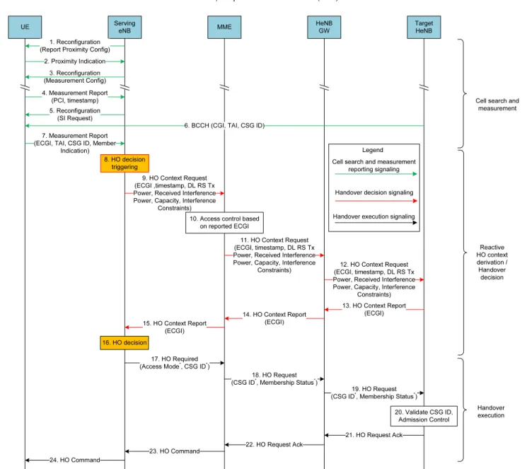
serving LTE cell, along with auxiliary cell status parameters such as (a) residual user capacity, (b) unutilized cell bandwidth, and (c) maximum allowed radiated power per direction for interference mitigation, to further enhance the HO decision efficacy. The entire HO decision parameter set will be referred to as HO context in the following. Depending on whether the required HO context is re-ported and maintained in a LTE CN entity or not, e.g., the MME, two different network signaling approaches are identified i.e. the reac-tive and the proacreac-tive. In the reacreac-tive approach the HO context is obtained on request towards the target LTE cell, while in the proac-tive approach it is directly obtained on request to the MME. To em-ploy the latter, the LTE cells are required to report their HO context status to the MME on a periodic basis. The reporting periodicity should be MME-configured and adapted according to the HO con-text request history, the LTE CN status and so on. Assuming that the serving eNB can be either a regular eNB or a HeNB,Figs. 1 and 2illustrate the detailed network signaling[3]required in the reac-tive and the proacreac-tive HO context derivation approaches, respec-tively. Without loss of generality, it is considered that the serving and the target cell are connected to the same MME.
The cell search and measurement signaling steps for both ap-proaches, i.e., steps 1–7 in the reactive and steps 5–11 in the pro-active, are in accordance with[3]. During these steps, the serving eNB configures the UE to identify an appropriate neighbor cell set and derive consistent RSRP and RSRQ measurements. Notice that the measurement configuration and reporting phase in LTE is triggered on critical events[20], e.g., when the serving cell RSRP is below a network-configured threshold for a network-configured time period TTT. To facilitate subsequent Pc
RS and Ic parameter
acquisition, each measurement report includes a measurement timestamp. The proximity configuration and indication signaling inFigs. 1 and 2is utilized for UE-based autonomous HeNB discov-ery, while the System Information (SI) acquisition and report sig-naling is required for HeNB identification and access control validation[3]. The serving eNB utilizes the reported UE measure-ments, sent on critical LTE events, for HO decision triggering (steps 8 in the reactive and 12 in the proactive approach)[3].
Upon HO decision triggering, the serving eNB initiates a HO context request towards the MME including the corresponding measurement timestamp and target ECGI, i.e. steps 9 in Fig. 1
and 13 in Fig. 2. To minimize unnecessary network signaling, the MME verifies the access status of the tagged UE on the target ECGI in steps 10 and 14, respectively. If the tagged user is not al-lowed to access the target eNB, the MME notifies the serving LTE cell accordingly. The key difference between the reactive and the proactive approaches is that in the former the MME forwards the HO context request towards the target eNB (steps 11–15), while in the latter the MME may directly provide the required HO con-text by utilizing the reports derived in steps 1–4 (Fig. 2). It should be noted that the proactive context derivation signaling phase is indicatively located in steps 1–4, since it can be performed asyn-chronously with respect to the rest HO signaling procedure. In the absence of HO context close to the required measurement time-stamp, the MME may decide to forward the HO context request towards the target eNB as in the reactive approach. Upon HO con-text acquisition, the HO decision algorithm in the serving eNB proceeds to a HO execution whenever necessary. In that case, a common HO execution signaling follows for both approaches (steps 17–24)[3]. HMUPCM c;ðdBÞ ¼ ðP c RS;ðdBÞP s RS;ðdBÞÞ X r2Rs;UL 1 Rc;UL ði c rP u!s UL RSRP u!s Ps RS Þ 0 @ 1 A ðdBÞ 0 B @ X r2Rs;UL 1 Rs;ULisr 0 @ 1 A ðdBÞ 1 C A ð2:2:16Þ
The HO context requests and reports can be signaled in an aggregated manner in both the access (eNB, HeNB) and the core LTE network (MME, HeNB GW). For example, on multiple HO con-text requests towards a tagged eNB, the MME may send an aggre-gated HO context request including all the required measurement timestamps. A similar approach can be applied for the HO context report in the reverse direction. Although the reactive approach minimizes the required signaling between the MME and the target LTE cell, the overall network signaling will be highly correlated to the occurrence rate of HO triggering events. On the other hand, more frequent yet more deterministic signaling overhead is ex-pected in the proactive approach, provided that the MME config-ures the HO context reporting periodicity on the eNBs. In addition to that, the proactive approach may significantly reduce the resulting HO decision delay compared to the reactive approach, provided that the HO context resides on the context-aware MME rather than the target LTE cell. However, certain operational enhancements are required in the MME to resourcefully support the proactive approach, in contrast with the reactive approach where no further LTE CN enhancements are needed.
3.2. The proposed HO decision algorithm
The proposed algorithm is based on the UPCM HO decision pol-icy described in Section 2.2, and is summarized inFig. 3. Upon HO decision triggering, the proposed algorithm initiates a HO timer (step 1) to avoid intolerable HO decision delay originating from ran-dom HO context derivation times. The HO timer value is initially set totHO=Tmax, whereTmaxis assumed to be adapted with respect to
the LTE critical events described in[20]. To minimize the resulting HO decision signaling and delay overhead, an aggregated HO con-text request is forwarded to the MME (step 2). Furthermore, a queue structureAis utilized both to mitigate potentially divergent HO context report inter-arrival times and to avoid an algorithmic dead-lock during the HO decision phase. Each neighbor cell set member inLuis initially included inA(step 3), to be subsequently
evaluated in a sequential manner. If the HO context for the queue head is absent, the proposed algorithm postpones the evaluation of the respective neighbor cell rather than waiting for the respective HO context report (step 4), i.e., cellc is moved to the end of the queue and the next neighbor cell inAis evaluated.
Fig. 1.Network signaling procedure for the reactive handover approach.
In the presence of the required HO context, the proposed algo-rithm investigates whether the tagged user is allowed to access the target cell and whether the target cell is capable of supporting another LTE user (step 5). The former is facilitated by the MME ac-cess control procedure preceding the HO context request towards the target cell, while the latter is based on the derived HO context on the target cell. Both these operations are performed to minimize the HO failure probability due to access control restrictions and capacity limitations in the target cell. The average uplink power transmission in the target cell is subsequently evaluated, to verify whether the maximum allowed UE power transmission capability
PuUL and the respective interference limitation constraintPcUL are met (step 6). The former is subjected to the UE power class[21], while the latter is applied whenever such a maximum allowed uplink power constraint is reported for the target cell. The neighbor cells which meet the above criteria are subsequently evaluated in accordance with the UPCM HO criterion in(2.2.17)(step 7). The pro-posed algorithm terminates the loop either when the entire neigh-bor cell set has been evaluated (step 8) or upon HO timer expiry (step 9). In the absence of neighbor cells with preferential UE power consumption, a reconfiguration procedure is triggered towards the
respective cell search and measurement reporting controller (step 10). In the opposite case, a HO execution is triggered towards the neighbor cell with the lower UE power consumption (step 11).
4. Numerical results
This section includes selected numerical results to evaluate the performance of the proposed UPCM-based HO decision algorithm in the integrated LTE macrocell–femtocell network. The simulation scenario is developed in MATLAB in accordance with the evalua-tion methodology described in [22]. The proposed HO decision algorithm is compared against: (a) a strongest cell based algorithm, referred to as the SCB algorithm, and (b) the HO decision algorithm described in[9], referred to as the Zhang algorithm.
A conventional hexagonal LTE network is considered, including a main LTE cluster composed of seven LTE cells, where each LTE cell consists of three hexagonal sectors. The wrap-around tech-nique is used to extend the LTE network, by copying the main LTE cluster symmetrically on each of the six sides [17]. A set of blocks of apartments, referred to as femtoblocks, are uniformly Fig. 2.Network signaling procedure for the proactive handover approach.
dropped within the main LTE cluster according to a scenario-related parameterdFBindicating the femtoblock deployment
den-sity within the main LTE cluster. The femtoblocks are modeled in accordance with the dual stripe model for dense urban environ-ments in [22]. According to it, each femtoblock consists of two stripes of apartments separated by a 10 m wide street while each stripe has two rows ofA= 5 apartments of size 1010 m. The fem-tocells are deployed with respect to a femtocell deployment ratio parameterrfc, indicating the probability of deploying a femtocell
inside an apartment[22]. The femtocell activation ratioafc= 0.9
is also introduced to model whether a femtocell is active or not
[2]. Each femtocell is initially considered to provide service to one associated user, while it is assumed capable of serving up to
4 users. Both the femtocell site and the associated user are uni-formly dropped inside the apartment. Each LTE user is considered capable of accessing up to one CSG, while the CSG ID group per LTE user and femtocell is uniformly picked from the CSG set {1,2,3}. Ten macrocell users are uniformly distributed within each LTE sec-tor, while both the femtocell and the macrocell users may freely move within the LTE cluster area in accordance with the mobility model summarized inTable 2. Unless differently stated, the user mobility model is characterized by an average user speed
m
¼3 km/h and a standard speed deviationsu= 1 km/h.The macrocell stations operate in a LTE band centered at 2000MHz, divided intoR RBs of width 180 KHz and utilizing a 5MHz bandwidth. The macrocell inter-site distance is set to Fig. 3.Proposed UPCM-based HO decision algorithm.
500m, while the operating band for each femtocell is uniformly picked from a band set including the macrocell operating band and its two adjacent frequency bands of 5MHz bandwidth. The adopted Modulation and Coding Schemes (MCS) are in accordance with[18], while the Exponential Effective SINR Mapping method is used to obtain the effective SINR per RB and the consequential UE throughput[22]. The minimum required SINR per UE is set to
c
us= 3 dB, while the communications are carried out in full buffer as in
[22]. The shadowing standard deviation for the macro and femto systems are 8 and 4 dB respectively, and the macrocell and femto-cell noise figures are set to 5 and 8 dB in that order. The macrofemto-cell downlink RS power transmissions are normally distributed with a mean value of 23 dBm and a standard deviation of 3dB, while the respective femtocell downlink RS power transmissions are uni-formly distributed within the [0,10] dBm interval. The UE power class is set to 23dBm and the maximum transmission powers for the macrocell and femtocell stations are set to 43 and 10dBm
[22], respectively. The adopted path loss models are depicted in
Table 2, where d and dindoor are the total and indoor distances
between the tagged cell and the tagged user in meters, respec-tively. The term 0.7dindoortakes into account the penetration losses
due to indoor walls,wcorresponds to the number of walls separat-ing the UE and the target cell, whileLow= 15 dB andLiw= 5 dB
cor-respond to the penetration losses of the building external and internal walls, respectively. The frequency-selective fading is con-sidered to follow the Rayleigh distribution[12]. Finally, the overall simulation time is set to 1000 sec and the simulation unit is set to 1 sec.
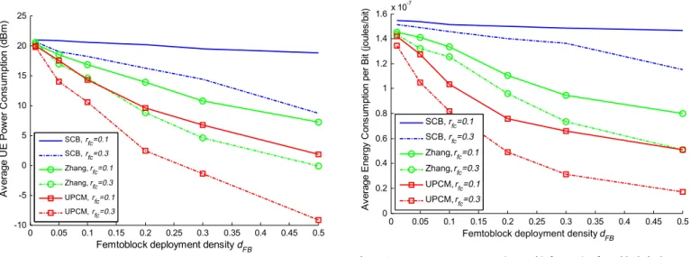
Fig. 4 and 5depict the performance of the HO decision algo-rithms under scope, in terms of UE average power consumption and average energy consumption per bit, respectively. Note that an increased femtoblock deployment density dFB corresponds to
an increased number of femtocells and UEs within the main LTE cluster. The same implies for an increased femtocell deployment ratiorfc, which corresponds to an increased femtocell and UE
den-sity within each femtoblock. As expected, an increasing femtoblock deployment densitydFBor femtocell deployment ratiorfcresults in
lower UE power and energy consumption per bit for all the HO decision algorithms. However, a higher femtocell deployment ratio
rfcis required for the SCB algorithm to benefit from the femtocell
potential for lower power emissions. Even though both the Zhang and the proposed UPCM algorithm result in improved UE power consumption (Fig. 4) and energy consumption per bit (Fig. 5), compared to the SCB algorithm, the proposed algorithm attains a comparably improved performance owing to its awareness on the actual downlink RS and received interference power at the can-didate LTE cell sites. In more detail, forrfc= 0.1 the proposed
algo-rithm attains a lower UE power consumption compared to the SCB and the Zhang algorithm, varying from 1 to 17 dB, and 0.5 to 5.4 dB, respectively. The same implies for a denser femtocell deployment ratiorfc= 0.3, where the derived UE power consumption gain varies
between 1 to 19 dB compared to the SCB algorithm, and between 0.5 to 9 dB compared to the Zhang algorithm. A significantly lower UE energy consumption per bit is also required for the proposed algorithm, which varies between 10 to 86% compared to the SCB algorithm, and between 4 to 66% compared to the Zhang algorithm, Table 2
Mobility and path loss models. Parameter Value Mobility
model
[12]
User speed at timet mt¼Nðm;suÞ(m/s)
User direction at timet /t¼Nð/t1;2p/t1tanð
ffiffiffiffi mt
p
2ÞDtÞ, wheremis the mean user speed,suthe user speed standard deviation,Dtthe
time period between two consecutive updates of the model andN(a,b)indicates a Gaussian distribution of meanaand standard deviationb
Path loss model [22] UE to macrocell UE outdoors PL(dB) = 15.3 + 37.6 log10d UE indoors PL(dB) = 15.3 + 37.6 log10d + Low UE to femtocell UE in the same apartment stripe PL(dB) = 38.46 + 20 log10d+ 0.7dindoor+ wLiw UE outside the apartment stripe
PL(dB) = max (15.3 + 37.6 log10d, 38.46 + 20 log10d) + 0.7dindoor+ wLiw+ Low
UE inside a different apartment stripe
PL(dB) = max (15.3 + 37.6 log10d, 38.46 + 20 log10d) + 0.7dindoor+ wLiw+2Low
0 0.05 0.1 0.15 0.2 0.25 0.3 0.35 0.4 0.45 0.5 -10 -5 0 5 10 15 20 25
Femtoblock deployment density d FB A v er age U E P o w e r C ons um pt ion ( d B m ) SCB, rfc=0.1 SCB, rfc=0.3 Zhang, rfc=0.1 Zhang, rfc=0.3 UPCM, rfc=0.1 UPCM, rfc=0.3
Fig. 4.Average UE power consumption for varying femtoblock deployment density.
0 0.05 0.1 0.15 0.2 0.25 0.3 0.35 0.4 0.45 0.5 0 0.2 0.4 0.6 0.8 1 1.2 1.4 1.6x 10 -7
Femtoblock deployment density dFB
A v er age E ner gy C o ns um pt ion per B it ( joules /b it ) SCB, rfc=0.1 SCB, rfc=0.3 Zhang, rfc=0.1 Zhang, rfc=0.3 UPCM, rfc=0.1 UPCM, rfc=0.3
Fig. 5.Average UE energy consumption per bit for varying femtoblock deployment density.
with respect to the femtoblock deployment density and the femto-cell deployment ratio (Fig. 5).
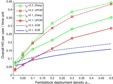
The UPCM algorithm reduces the average power consumption of the LTE cells as well (Fig. 6), as a result of the substantial interfer-ence mitigation achieved in the LTE downlink in terms of RSSI and in the LTE uplink in terms of Received Interference Power (RIP) at the LTE cells (Fig. 7). Both these effects are a direct outcome of the proposed algorithm’s tendency to facilitate mobility towards cells that utilize bands with lower Received Interference Power. The latter effect reduces the number of UE interferers in congested LTE bands, and condenses the overall UE power transmissions per band. Although the incorporation of the proposed UPCM algorithm achieves substantial energy consumption and interference mitiga-tion gains, an increased number of HO execumitiga-tion events per user is observed compared to the SCB algorithm (Fig. 8). The same implies for the Zhang algorithm as well, provided that both the proposed and the Zhang algorithms extend the femtocell utilization time, which increases the sensitiveness on user mobility and results in more frequent HO execution events (Fig. 8). Nevertheless, the increased number of HO execution events per user can be lowered by employing standard mobility-centric HO margin HMc,(dB) adaptation techniques similar to the ones followed in the SCB case
[5–8,10]. The following results are derived fordFB= 0.1 andrfc= 0.2,
while three different mean user speed values are considered i.e. 3, 60 and 125 km/h.
Fig. 9illustrates the overall number of HO execution events per user and time unit versus theHMc,(dB)value. As expected, for
mod-erate to high user speeds an increased number of HO execution events per user and time unit are observed for the SCB and the pro-posed UPCM algorithm. For a suitableHMc,(dB)parameter
adapta-tion, however, the HO execution events for the UPCM algorithm are moderated and converge to the number of HO execution events corresponding to the SCB algorithm with lowerHMc,(dB)values. On
the other hand, the Zhang algorithm attains a significantly low number of HO execution events for moderate to high user speeds, compared to the SCB and the proposed algorithm, owing to the con-dition of disabling inbound mobility to femtocells whenever the user speed exceeds over the value of 30 km/h (Fig. 9). Nevertheless, this improvement at moderate to higher user speeds is attained at the cost of substantially increased energy expenditure (Fig. 10).
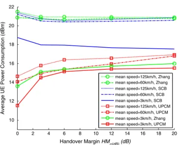
The impact of an increasedHMc,(dB)parameter and mean user
speed, on the consequential UE power consumption gain is depicted inFig. 10. It can be seen that under moderate to high mean user speeds the Zhang and the SCB algorithm attain a similar behavior, which remains unaffected for a varyingHMc,(dB)parameter.
More-over, both the Zhang and the SCB algorithms result in substantially higher UE power consumption compared to the proposed UPCM algorithm under moderate to high user speeds, which varies
0 0.05 0.1 0.15 0.2 0.25 0.3 0.35 0.4 0.45 0.5 0 5 10 15 20 25
Femtoblock deployment density d FB
Average LTE cell Power Consumption (dBm)
SCB, rfc=0.1 SCB, rfc=0.3 Zhang, rfc=0.1 Zhang, rfc=0.3 UPCM, rfc=0.1 UPCM, rfc=0.3
Fig. 6.Average LTE cell power consumption for varying femtoblock deployment density. 0 0.1 0.2 0.3 0.4 0.5 -110 -105 -100 -95 -90 -85 -80 -75
Femtoblock deployment density dFB
Average Interference Power (dBm)
UE RSSI, Zhang, rfc=0.1 UE RSSI, Zhang, r fc=0.3 UE RSSI, SCB, rfc=0.1 UE RSSI, SCB, rfc=0.3 UE RSSI, UPCM, r fc=0.1 UE RSSI, UPCM, rfc=0.3 Cell RIP, Zhang, rfc=0.1 Cell RIP, SCB, rfc=0.1 Cell RIP, UPCM, rfc=0.1 Cell RIP, Zhang, rfc=0.3 Cell RIP, SCB, rfc=0.3 Cell RIP, UPCM, rfc=0.3
Fig. 7.Average UE RSSI and cell received interference power for varying femtoblock deployment density. 0 0.05 0.1 0.15 0.2 0.25 0.3 0.35 0.4 0.45 0.5 0 0.05 0.1 0.15 0.2 0.25 0.3 0.35 0.4 0.45
Femtoblock deployment density dFB
Overall HO per user / time unit
rfc=0.3, Zhang rfc=0.3, UPCM rfc=0.1, Zhang rfc=0.1, UPCM rfc=0.3, SCB rfc=0.1, SCB
Fig. 8.HO execution events per user and time unit for varying femtoblock deployment density. 0 2 4 6 8 10 12 14 16 18 20 0 0.05 0.1 0.15 0.2 0.25 Handover Margin HMc(dB) (dB)
Overall HO per user / time unit
mean speed=3km/h, Zhang mean speed=125km/h, UPCM mean speed=60km/h, UPCM mean speed=3km/h, UPCM mean speed=125km/h, SCB mean speed=60km/h, SCB mean speed=3km/h, SCB mean speed=60km/h, Zhang mean speed=125km/h, Zhang
Fig. 9.HO execution events per user and time unit for varying handover margin.
according to theHMc,(dB)parameter. Under low mobility scenarios
(3 km/h), an increasedHMc,(dB)parameter improves the UE power
consumption performance for the SCB algorithm, as it extends the femtocell service time even if the RSRP status of a neighbor cell exceeds over the tagged femtocell RSRP status. On the contrary, the derived UE power consumption gain for the Zhang lowers for an increasedHMc,(dB)parameter, given that HO executions towards
femtocells with relatively improved propagation characteristics are prevented. Similar behavior is observed for the proposed UPCM algorithm as well, where an increased HMc,(dB) parameter raises
the required UE power consumption provided that mobility to-wards a neighbor LTE cell is allowed only if the expected UE power consumption gain exceeds over the respective HMc,(dB) value.
Nevertheless, the proposed algorithm results in significantly lower UE power consumption compared to both the SCB and the Zhang algorithm, varying from 3 to 8 dB, and 0.5 to 8 dB, respectively, depending on the current user speed and the adoptedHMc,(dB)value.
5. Conclusion
In this paper a novel HO decision policy has been described, to-wards minimizing the UE power consumption in the integrated LTE macrocell–femtocell network. The proposed UPCM policy enhances the strongest cell HO decision policy by introducing an adaptive HHM, incorporating standardized LTE measurements on the tagged user’s neighbor cells. To resourcefully facilitate the employment of the proposed UPCM policy, the required LTE network signaling pro-cedures have been thoroughly described, while a UPCM-enhanced HO decision algorithm has also been proposed. Although the pro-posed HO decision algorithm necessitates an increased LTE network signaling, numerical results have shown that substantial power consumption and interference mitigation gains are ultimately de-rived. Compared to a strongest cell based HO decision algorithm, the proposed algorithm has shown to reduce the LTE UE and cell power consumption by up to 19 and 13 dB, respectively, and en-hance the UE energy consumption per bit by up to 85% with respect to the femtocell deployment density within the LTE network. Com-pared to another competing HO decision algorithm, the proposed algorithm has also shown to attain significantly lower UE and cell power consumption by up to 9 and 7.5 dB, respectively, and en-hanced UE energy consumption per bit by up to 66% as well. It
has also been shown that standard mobility-centric HO margin adaptation techniques can be utilized to moderate the increased HO execution rate per UE for the proposed UPCM-based algorithm. Even though an increased HO mobility margin suppresses the dif-ferential power consumption gains, significantly lower UE power consumption can be still attained compared to the predominant strongest cell HO decision policy and other competing schemes. Acknowledgment
This paper has been partially funded by the C2POWER (FP7-ICT-248577), GREEN-T (CP8-6), GREENET (FP7-PEOPLE 264759), CO2-GREEN (TEC2010-20823) projects, and co-financed by the EU (European Social Fund – ESF) and Greek national funds through the Operational Program ‘‘Education and Lifelong Learning’’ of the National Strategic Reference Framework (NSRF) – Research Funding Program: Heracleitus II. Investing in knowledge society through the European Social Fund.
References
[1] V. Chandrasekhar, J. Andrews, A. Gatherer, Femtocell networks: a survey, IEEE Communications Magazine 46 (9) (2008) 59–67.
[2] A. Galindo-Serrano, L. Giupponi, M. Dohler, Cognition and Docition in OFDMA-Based Femtocell Networks, 2010 IEEE Global Telecommunications Conference, Dec 2010, pp. 1–6.
[3] 3GPP, ‘‘E-UTRA and E-UTRAN Overall Description’’, TS 36.300 V10.1.0 (2010– 10).
[4] A. Golaup, M. Mustapha, L.B. Patanapongpibul, Femtocell access control strategy in UMTS and LTE, IEEE Communications Magazine 47 (9) (2009) 117–123.
[5] W. Shaohong, Z. Xin, Z. Ruiming, Y. Zhiwei, F. Yinglong, Y. Dacheng, Handover study concerning mobility in the two-hierarchy network, in: IEEE 69th Vehicular Technology Conference, Apr. 2009, pp. 1–5.
[6] A. Ulvan, R. Bestak, M. Ulvan, Handover scenario and procedure in LTE-based femtocell networks, in: The 4th International Conference on Mobile Ubiquitous Computing, Systems, Services and Technologies, Oct. 2010.
[7] S. Sesia, I. Toufik, M. Baker, LTE – The UMTS Long Term Evolution: From Theory to Practice, John Wiley & Sons, ISBN: 978-0-470-69716-0, 2009.
[8] Z. Becvar, P. Mach, Adaptive hysteresis margin for handover in femtocell networks, in: 6th International Conference on Wireless and Mobile, Communications, Sept. 2010, pp. 256–261.
[9] H. Zhang, X. Wen, B. Wang, W. Zheng, Y. Sun, A novel handover mechanism between femtocell and macrocell for LTE based networks, in: Second International Conference on Communication Software and Networks 2010 (ICCSN ‘10), Feb. 2010, pp. 228–231.
[10] K. Dimou, M. Wang, Y. Yang, M. Kazmi, A. Larmo, J. Pettersson, W. Muller, Y. Timner, Handover within 3GPP LTE: design principles and performance, in: IEEE 70th Vehicular Technology Conference Fall, Sept. 2009, pp. 1–5. [11] I. Ashraf, L.T.W. Ho, H. Claussen, Improving energy efficiency of femtocell base
stations via user activity detection, IEEE Wireless Communications and Networking Conference 2010 (Apr. 2010) 1–5.
[12] J. Zhang, G. de la Roche, Femtocells: Technologies and Deployment, John Wiley & Sons Ltd, ISBN 978-0-470-74298-3, 2010.
[13] G. Boudreau, J. Panicker, G. Ning, R. Chang, N. Wang, S. Vrzic, Interference coordination and cancellation for 4G networks, IEEE Communications Magazine 47 (4) (Apr. 2009) 74–81.
[14] M. Yavuz, F. Meshkati, S. Nanda, A. Pokhariyal, N. Johnson, B. Raghothaman, A. Richardson, Interference management and performance analysis of UMTS/ HSPA+ femtocells, IEEE Communications Magazine 47 (9) (2009) 102–109. [15] O. Simeone, E. Erkip, S. Shamai Shitz, Robust transmission and interference
management for femtocells with unreliable network access, IEEE Journal on Selected Areas in Communications 28 (9) (Dec. 2010) 1469–1478.
[16] H. Leem, S.Y. Baek, D.K. Sung, The effects of cell size on energy saving, system capacity, and per-energy capacity, in: IEEE Wireless Communications and Networking Conference, Apr. 2010, pp. 1–6.
[17] F. Cao, Z. Fan, The tradeoff between energy efficiency and system performance of femtocell deployment, in: The 7th International Symposium on Wireless Communication Systems (ISWCS), Sept. 2010, pp. 315–319.
[18] 3GPP, LTE physical layer; General description, TS 36.201 V10.1.0 (2010–12). [19] 3GPP, Physical layer; Measurements, TS 36.214 V10.0.0 (2010–12). [20] 3GPP, Radio Resource Control (RRC); Protocol specification, TS 36.331 V10.0.0. [21] 3GPP, User Equipment (UE) radio transmission and reception, TS 36.101
V10.1.0.
[22] Femto Forum, Interference Management in OFDMA Femtocells, Femto Forum, Mar. 2010. 0 2 4 6 8 10 12 14 16 18 20 10 12 14 16 18 20 22 Handover Margin HMc(dB) (dB)
Average UE Power Consumption (dBm)
mean speed=125km/h, Zhang mean speed=60km/h, Zhang mean speed=125km/h, SCB mean speed=60km/h, SCB mean speed=3km/h, SCB mean speed=125km/h, UPCM mean speed=60km/h, UPCM mean speed=3km/h, Zhang mean speed=3km/h, UPCM
Fig. 10.Average UE power consumption for varying handover margin.