Build Height Effect on the Inconel 718 Parts Fabricated
by Selective Laser Melting
Xiaoqing Wang, Tahmina Keya, Kevin Chou
Department of Mechanical Engineering The University of Alabama
Tuscaloosa, AL 35487
xwang127@crimson.ua.edu, tkeya@crimson.ua.edu, kchou@eng.ua.edu
Abstract
Selective laser melting (SLM) is an emerging metal additive manufacturing (AM) technology. It has been employed in many applications including propulsion components which are made of nickel-based superalloys, such as Inconel 718. In this study, the effect of the build height on the mechanical properties and microstructure of SLM-processed Inconel 718 parts was investigated. The samples were cut from the Inconel 718 build part after stress relief. They were prepared for microstructure
observations and nanoindentation testing. The results are summarized as following. Young’s modulus
and hardness obtained from the nanoindentation tests are comparable with or superior to that from traditional manufacturing methods. In addition, there do not appear significant differences in mechanical properties along the build height of the parts, though the columnar grains of the side-surface specimens are narrower at the bottom layers of the part. Moreover, the texture analysis results imply no significant anisotropic characteristics for the mechanical properties between the scanning surface and the side surface of the build parts.
Keywords: Inconel718, Mechanical properties, Microstructure, Nanoindentation, Selective Laser Melting
1 Introduction
Additive manufacturing (AM) developing from 1980s (Hull, 1986) has attracted industry. It can manufacture complex components directly from a computer aided design (CAD) file without other moulds and tools for cast or substantial machining. This will save a lot of time, cost and material that otherwise will be wasted using traditional methods (Strondl, et al., 2008; Murr, et al., 2011; Brandl, et al., 2012; Gebhardt, et al., 2010; Gong, et al., 2015; Gao, et al., 2008; Song, et al., 2011; Feng and Burkett, 2015; Qian, et al., 2014). This has made it as one of the rapidly developing advanced manufacturing techniques in the world (Chlebus, et al., 2015; Wang, et al., 2012; Jia and Gu, 2014; Lu, et al., 2015; Gong, et al., 2014), and various studies have been conducted (Qian, et al., 2014; Kruth, et
Volume 5, 2016, Pages 1006–1017
44th Proceedings of the North American Manufacturing Research Institution of SME http://www.sme.org/namrc
al., 1998; Dong and Wang, 2008). AM techniques have critical applications for the aerospace and biomedical industries materials, such as titanium alloys, aluminide, and nickel-based alloys. Because they are expensive materials and most appropriate for small production due to their relatively low production rates.
Selective Laser Melting (SLM), as a promising powder-bed AM technology, could selectively melt powder layer by the action of a high energy laser beam that performs a complete fusion of one layer to another producing complex components with high dimensional precision and good surface integrity precisely (Dadbakhsh and Hao, 2012; Song, et al., 2013; Vrancken, et al., 2012; Zhang, et al., 2013). It has critical applications for aerospace materials, such as titanium alloys, aluminide, and nickel-based alloys (Liu, et al., 2015; Hu, et al., 2016; Hu, 2013; Liu, et al., 2014). IN718 alloy, having experienced extensive development over the past four decades (Ahmad, et al., 2008; González-Fernández, et al., 2012; Cozar and Pineau, 1973; Knorovsky, et al., 1989; Slama, et al., 1997), is a precipitation hardenable solid solution nickel–chromium alloy. It contains significant amounts of iron, niobium, and molybdenum along with lesser amounts of aluminum and titanium. However, it is difficult to manufacture the IN718 material by conventional machining methods at room temperature due to excessive tool wear and low material removal rates (Attia, et al., 2010; Costes, et al., 2007). Moreover, Inconel 718 parts with complex structures, high dimension precision and further elevated mechanical properties are in higher demand (Wang, et al., 2012). Therefore, the application of the novel non-traditional processing technology is necessary for the net shape production of Inconel 718 parts with complex configurations and high performance.
Experimental studies regarding microstructures of SLM processed Inconel 718 components have been carried out. Wang et al. (Wang, et al., 2012) found that a regular microstructure with good metallurgical bonding, minimal defects and fine dendritic grains is formed by SLM. Amato et al. (Amato, et al., 2012) observed that the fabricated components exhibited a more pronounced (FP7-SME-2008-2) columnar γ″ phase precipitate architecture parallel to the build direction (spaced at 0.8 μm). Since most the SLM Inconel 718 components are applied for the structural components, different mechanical properties have been investigated. Wang et al. (Wang, et al., 2012) studied the tensile properties of SLM built Inconel 718 specimens, and found that the yield strength and tensile strength are 903 MPa and 1143 MPa, respectively. Amato et al. (Amato, et al., 2012) found the tensile strength and microhardness are about 1120 MPa, and 3.9 GPa, respectively. It demonstrates that the mechanical properties of SLM fabricated specimens are comparable to those of cast or wrought specimens. The mechanical properties of SLM Inconel 718 are excellent enough to meet the expectations in the applications (Kruth, et al., 2005), and the detail of the tests can be seen in former studies (Gong, et al., 2015).
The characterizations of the SLM Inconel 718 also vary with the process conditions, such as the manufacturing process parameters and the shape features. Therefore, it is important to understand the effects of the process conditions during the building process. The height of the build part, also called build height, which may affect the microstructure and mechanical properties of the final part has not been studied yet, through various aspects in SLM Inconel 718 have been investigated. In this study, the objective is to study the effect of the build height on the mechanical properties and microstructure of an Inconel 718 part fabricated by SLM using nanoindentation test, optical scope (OM) and scanning electron microscope (SEM). The relationship among SLM build height and the characterization will be established.
2 Experimental details
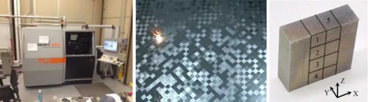
In this study, a Concept Laser M2 Laser Cusing System at NASA’s Marshall Space Flight Center (Huntsville, AL), as shown in Figure 1, was used to fabricate the solid block modeled from CAD software with a dimension of 40 mm by 40 mm by 6 mm. The M2 system has a maximum build plate
size of 250 mm 250 mm and a buildable height of 300 mm. It utilizes a computer-controlled continuous wave fiber laser with a fixed laser spot focus diameter of 150 μm and a maximum output of 200 W. It is directed to the powder bed using servo controlled reflectors which allow the laser spot to scan the surface of the bed at a maximum of 7000 mm/s. Besides, it can be manipulated by scanner system to form multiple laser beams with scanning velocity up to 7 ms-1 and to give a small spot size
of 70 ~ 200 μm.
In this study, fine pre-alloyed Inconel 718 powder was used as rough material to fabricate the block. During building each layer of the block, the laser beam moves across the powder-layer surface tracing the model cross-section boundary and then raster-scans thoroughly the inside of the contour using island scan strategy/pattern. The area inside of the contour was divided into 5mm squares named as islands. These islands were selectively melted in a random order with vectors in the adjacent islands perpendicular to each other. The whole pattern is rotated 45 degrees with respect to the substrate plate to reduce any possible interference between the recoated blade and the straight boundary of each individual island (Carter, et al., 2014). For each island, simple alternating scan vectors with speed of 600 mm/s have been used with scan spacing is 105 μm. The island pattern is shifted by 1 mm in both the X and Y direction for each subsequent layer. The detail of the parameters used in this study are listed in Table 1.
Figure 1. Laser Concept M2 Cusing System (a), island scanning pattern (b) and as-deposited part (c)
Table 1. Manufacturing parameters used in this study System Laser
Type
Spot
size, μm Power, W
Layer
thickness, μm spacing, μmHatch speed, mm/s Scanning
Scanning Pattern Concept Laser M2 CW Fiber 150 180 30 105 600 Island, 5mm
The standard metallographic procedures with vibratory finishing have been used to prepare the 8 Inconel 718 samples cut from the parts along the build height, in which S1 (Sample 1) to S4 are used to investigate the Y-plane and S5 to S8 are used to study the Z-plane. Then, the EBSD and nanoindentation tests were conducted on the surfaces of the well-prepared samples first. After that, they were etched to reveal the microstructures with an acid-based solution made of 20 ml hydrochloric acid (37 wt. %), 20 ml (68 wt. %) nitric acid and 1 g copper chloride. The etched metallographic samples were observed using a Leitz optical microscope (OM) and JEOL 7000 FE Scanning Electron Microscope (SEM). Nanoindentation tests were performed using a Triboindenter from Hysitron Inc. and a radius of 100 nm Berkovich tip. The details setting are same as in former study (Wang, et al., 2015). The indent pattern used in all the experiments is a matrix of 3 × 4 with spacing of 5 μm between any two horizontal or vertical adjacent points.
In Figure 2(a), the schematic of nanoindentation is shown where P is the applied load and h is indentation depth. A trapezoidal shaped loading and unloading method is applied with maximum force of 5000 µN which is shown in figure 2(b). In this method, the loading force goes up to 5000 µN in 5
seconds with a constant loading rate, holds it there for 2 seconds and then the unloading force goes back to zero in 5 seconds with a constant rate.
Figure 2 : (a) Schematic of nanoindentation (den Toonder, et al., 2005) and (b) Applied Load Function
3 Results and discussion
3.1 Microstructure observations
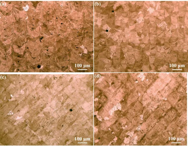
The optical examination of the samples reveals that columnar structures present on the Y-plane along the build direction and perpendicular to the melted powder layers. This is caused by the vertical heat flux related to heat transfer into the substrate. The Z-plane shows equiaxed grains, which results from the horizontal heat flux related to the movement of the heat source, as shown in Figure 3. During the manufacturing process, the growing grains align themselves with the steepest temperature gradients. This results in columnar shaped morphology with its width(146.77 ± 11.04 µm) around the diameter of the spot size (150 µm), which is very common in high-energy materials processing based on rapid cooling from the melt (Wang and Chou, 2015; Xu, et al., 2015). The equiaxed grains are a result of epitaxial, dendritic grain growth in the direction determined by heat flux direction and crystallographically favored orientation (Ardakani, et al., 2000). Therefore, same as observed by Amato et al. (Amato, et al., 2012) and Gong et al (Gong, et al., 2015), the grains would be in a rod-shape if the observation in both Y-plane and Z-plane is considered.
The effect of the build height on the width of the columnar structure is shown in Table 3. Generally, the average width of the columnar structures increase with the increase of the building height of the part until a stable stage reached. The bottom sample shows narrow and uniformly distributed columnar dendrites, which is caused by the larger cooling rate due to the higher thermal conductivity between the bottom layers and their direct connecting build substrate plate, which has a lower temperature (about 300 °C) compared to the melt pool of Inconel 718, as shown in Figure 3 (b). Increasing of the cooling rate will form smaller columnar grains (Gockel and Beuth, 2013), because more nuclei could be generated at a higher cooling rate. This will further form finer grains in long and narrow columnar morphology. Besides, the cooling rate changes with the build height of the part during the manufacturing process. This leads to the transition of the microstructure and further results in the larger standard deviation for the width of the columnar structures in the top and middle-bottom samples, as listed in Table 3. Same for the top sample, as shown in Figure 4 (a), it presents clear transition of the columnar microstructure at the very top area where the width value decrease from ~147 µm to ~75 µm. This is because the top layers are close to the end of the manufacturing process, which means they are direct touching the environment temperature in the chamber. This leads to a higher cooling rate compared to that in the middle of the part.
0
2000
4000
6000
0
5
7
12
Force, µ
N
Time, s
(a)
100
μ
m
(b)
100
μ
m
(c)
100
μ
m
(d)
100
μ
m
Figure 3. Optical micrograph showing etched microstructure in the Y-plane (a) S2 and (b) S4, and Z-plane (c) S6 and (d) S8
Table 2. Measured characteristic sizes SLM samples with build height.
Sample
Columnar structure width (µm)
Average Standard deviation
Top (S1) 112.45 38.02
Middle-Top (S2) 146.77 11.04 Middle-Bottom (S3) 111.40 38.33
Bottom (S4) 74.92 9.39
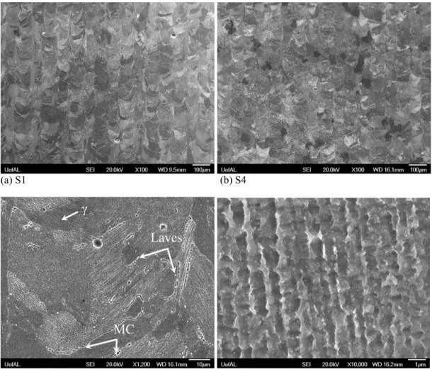
In addition, there are some shallow color area on the surface and the bottom sample has a higher proportion than others. Under the scanning electron microscope (SEM), it can be seen from Figure 4 (d) that a fine dendritic structure is formed within the wide columnar structure with their growth direction downwards or towards to the bottom of the cut ends of melted tracks, which can be seen in the form of a series of arcs induced by the Gauss energy distribution of laser beam, showing the heat flux direction during the solidification process within the molten pool. Same for the inter-dendritic regions of the wide columnar structure, the majority growth direction of the dendrites are upwards.
With higher magnification, it can be seen that shallow color area under optical scope are filled with
the γ basic phase and Laves phase particles. The width of the fine dendrites are around 1 µm.
It is known that Inconel 718 is a basic γ phase alloy, also called γ matrix, with two major
precipitated strengthening disk-shaped γ″ phase and spheroidal γ′ phase (Wang, et al., 2016). There are also some needle/plate-like δ phase, discrete metal-carbide (MC) particles and round, island-like Laves phase (Huang, et al., 1996). Besides, there are some other phases and some minor segregation also appeared at the boundaries of the grains, which are mainly carbides (MC) (Gong, et al., 2015), as shown in the Figure 4 (c). In addition to that, there are some pores on the images, which can also be seen from Figure 3.
(a) S1 (b) S4
(c) Interdendrites regions on S4 (d) Fine dendrites on S4
Figure 4. Scanning electron microscope (SEM) images showing microstructure evolution in the Y-plane
3.2 Nanoindentation test
Take one test as an example, the 12 depth vs. displacement curves from 12 points in the matrix are illustrated in Figure 5. The average maximum indentation depth was about 139.04 nm, and the
ଵ ாೝ
ൌ
ଵିఔమ ா
ଵିఔೞమ ாೞ(1)
where νi is the Poisson’s ratio of indenter, 0.07, Ei is the Young’s modulus of the indenter, 1140
GPa, νs is the Poisson’s ratio of Inconel 718 samples, 0.294 and Er is the Young’s modulus of the
Inconel 718 samples directly obtained from the tests. The hardness is calculated by following equation:
ܪ ൌ ೌೣ
ೝ
(2)
where Pmax is the maximum load applied and Ar is the residual area left by the indenter, which is
evaluated from the shape function of the indenter and the maximum indent displacement
For the two typical test curves obtained from the nanoindentation test are shown in Figure 5 with
the Young’s modulus of 177.3 GPa and 219.0 GPa, respectively. The results from the nanoindentation tests are concluded in Figures 6 and 7.
Figure 5. Load vs. displacement curve from the nanoindentation test
Figure 6. Young’s Modulus for the SLM-processed Inconel 718 alloy
0 30 60 90 120 150 0 1000 2000 3000 4000 5000 Displacement, nm F o rc e, uN E=177.3 GPa E=219.0 188.9 210.6 211.1 202.8 100 130 160 190 220 S1 S2 S3 S4 E, GP a Y-plane (a) 193.7 193.4 201.2 196.2 100 130 160 190 220 S5 S6 S7 S8 E, GP a Z-plane (b)
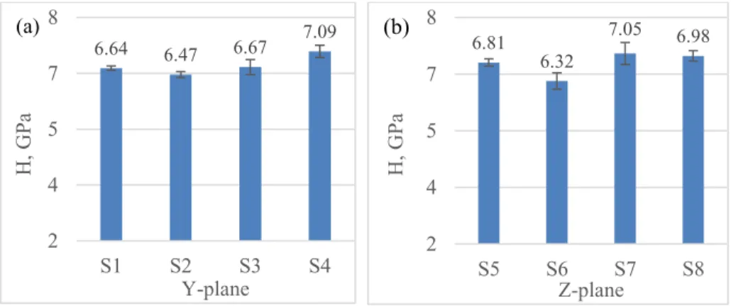
Figure 7. Nano-hardness of SLM-processed Inconel 718 alloy
Generally, it can be inferred from Figure 6 and 7 that there is no significant changing trend for the elastic modulus along the build height. Even though the samples from the middle portion of the part have a higher elastic modulus than that of the top and bottom on the Y-plane, there is no significant difference on the Z-plane. Both the values are comparable with or superior than the literature values and wrought material (Wang, et al., 2016). For the average hardness values on the Y-plane, the bottom sample shows the highest value, then decreases a little with the increase in the build height for the middle-bottom sample, and increases against the end of the manufacturing process for the top sample. This is caused by the cooling rate during the solidification from the melting pool, same as that of electron beam additive manufacturing (EBAM) (Wang, et al., 2015; Gong and Chou, 2015). The different microstructure distribution results in the variation of changing trend of the values. The repeated heating may result in the softening of the already deposited layers, and such influence to the middle layers is mostly evident.
The highest hardness values are achieved from the bottom and top layers of the parts, which results from the manufacturing process since the mechanical properties of materials are strongly dependent on the microstructures. From the comparison between the width of the columnar microstructure of different layers, as shown in Table 2, it can be observed that the bottom and top layers achieve the smallest columnar structure width and the details can be found in another study (Wang and Chou, 2016). According to Hall-Petch relation(Callister and Rethwisch, 2013; Schuh and Nieh, 2002), the finer grain size results in the strength of the materials. From this point of view, that is why the middle-top sample 2 and sample 6 both have a relative lower hardness as they have the widest columnar structures. Most of the hardness values fall in the range of 6.08 – 7.20 GPa, which is 50% higher than the microhardness values obtained from Vickers’ indentation (Wang and Chou, 2015), which are around 3.9 – 4.3 GPa. Overall, the hardness values are superior than those found in the literatures due the higher cooling rate in solidification during the manufacturing process (Wang, et al., 2016). In addition, there are some difference between the Y-plane and the Z-plane for the mechanical properties, which may be caused by the different orientation of the grains. The two typical orientation maps with related pole figures are shown in Figures 8. Based on the EBSD results (Wang and Chou, 2016), the grains present a weaker crystallographic texture in the samples, and this will cause the less anisotropic characteristics of the mechanical properties.
6.64 6.47 6.67 7.09 2 4 5 7 8 S1 S2 S3 S4 H, GP a Y-plane (a) 6.81 6.32 7.05 6.98 2 4 5 7 8 S5 S6 S7 S8 H, GP a Z-plane (b)
(a) S1
(b) S4
(c) (d)
Figure 8. Typical orientation maps and their related pole figures of Top (S1) and Bottom (S4) samples from Y-plane of Inconel 718
4 Conclusions
In this study, the effect the build height on the mechanical properties and microstructure of Inconel 718 manufactured by selective laser melting (SLM) technology has been investigated. The samples were cut from the as-deposited Inconel 718 parts with wire-electrode and then prepared for microstructure observation and nanoindentation test. Based on the results from the nanoindentation test, the Young’s modulus and hardness are comparable with or superior to that in traditional methods or literature values. Besides, there is no obvious changing trend along the build height of the parts, even though the side-surface of the specimen from the bottom of the part presents narrower columnar grains. In addition, the parts do not show prominently anisotropic characteristics of the mechanical properties between the side surface (Y-plane) and scanning surface (Z-plane) based on the texture analysis results.
This research is supported by CFD Research Corporation (Huntsville, AL) through a NASA STTR project. Marshall Space Flight Center (Huntsville, AL) fabricated experimental samples. Dr. Mark L Weaver (University of Alabama) offered assistance with nanoindentation testing. XW also acknowledges the scholarship support from the Alabama EPSCoR GRSP.
References
Ahmad, M., Akhter, J. I., Shahzad, M., and Akhtar, M., (2008). "Cracking during solidification of diffusion bonded Inconel 625 in the presence of Zircaloy-4 interlayer," Journal of Alloys and Compounds, 457(1–2), pp. 131-134.
Attia, H., Tavakoli, S., Vargas, R., and Thomson, V., (2010). "Laser-assisted high-speed finish turning of superalloy Inconel 718 under dry conditions," CIRP Annals - Manufacturing Technology, 59(1), pp. 83-88.
Ardakani, M., D’Souza, N., Wagner, A., Shollock, B., and McLean, M., (2000). "Competitive grain growth and texture evolution during directional solidification of superalloys," TMS Superalloys, pp. 219-228.
Amato, K., Gaytan, S., Murr, L., Martinez, E., Shindo, P., Hernandez, J., Collins, S., and Medina, F., (2012). "Microstructures and mechanical behavior of Inconel 718 fabricated by selective laser melting," Acta Materialia, 60(5), pp. 2229-2239.
Brandl, E., Heckenberger, U., Holzinger, V., and Buchbinder, D., (2012). "Additive manufactured AlSi10Mg samples using Selective Laser Melting (SLM): Microstructure, high cycle fatigue, and fracture behavior," Materials & design, 34, pp. 159-169.
Costes, J. P., Guillet, Y., Poulachon, G., and Dessoly, M., (2007). "Tool-life and wear mechanisms of CBN tools in machining of Inconel 718," International Journal of Machine Tools and Manufacture, 47(7–8), pp. 1081-1087.
Carter, L. N., Martin, C., Withers, P. J., and Attallah, M. M., (2014). "The influence of the laser scan strategy on grain structure and cracking behaviour in SLM powder-bed fabricated nickel superalloy," Journal of Alloys and Compounds, 615, pp. 338-347.
Chlebus, E., Gruber, K., Kuźnicka, B., Kurzac, J., and Kurzynowski, T., (2015). "Effect of heat treatment on microstructure and mechanical properties of Inconel 718 processed by selective laser melting," Materials Science and Engineering: A, 639, pp. 647-655.
Callister, W. D., and Rethwisch, D. G., (2013). Fundamentals of materials science and engineering, Wiley.
Cozar, R., and Pineau, A., (1973). "Morphology of y’ and y” precipitates and thermal stability of inconel 718 type alloys," Metallurgical Transactions, 4(1), pp. 47-59.
Dong, L. X., and Wang, H. M., (2008). "Microstructure and corrosion properties of laser-melted deposited Ti2Ni3Si/NiTi intermetallic alloy," Journal of Alloys and Compounds, 465(1–2), pp. 83-89.
Dadbakhsh, S., and Hao, L., (2012). "Effect of Al alloys on selective laser melting behaviour and microstructure of in situ formed particle reinforced composites," Journal of Alloys and Compounds, 541(0), pp. 328-334.
den Toonder, J., Ramone, Y., Van Dijken, A., Beijer, J., and Zhang, G., (2005). "Viscoelastic characterization of low-dielectric constant SiLK films using nanoindentation in combination with finite element modeling," Journal of Electronic Packaging, 127(3), pp. 276-285.
FP7-SME-2008-2, (2008). "Detailed Report on Laser Cusing, SLA, SLS and Electron Beam Melting (including Technical, Economical and Safety Features)," No. GRANT AGREEMENT No 243631 Seventh Framework Programme.
Feng, Y., and Burkett, S. L., (2015). "Fabrication and electrical performance of through silicon via interconnects filled with a copper/carbon nanotube composite," Journal of Vacuum Science & Technology B, 33(2), p. 022004.
Gockel, J., and Beuth, J., (2013). "Understanding Ti-6Al-4V microstructure control in additive manufacturing via process maps," Solid Freeform Fabrication Proceedings, Austin, TX, Aug, pp. 12-14.
Gebhardt, A., Schmidt, F.-M., Hötter, J.-S., Sokalla, W., and Sokalla, P., (2010). "Additive Manufacturing by selective laser melting the realizer desktop machine and its application for the dental industry," Physics Procedia, 5, Part B(0), pp. 543-549.
Gong, X., Wang, X., Cole, V., Jones, Z., Cooper, K., and Chou, K., "Characterization of Microstructure and Mechanical Property of Inconel 718 From Selective Laser Melting," Proc. ASME 2015 International Manufacturing Science and Engineering Conference, American Society of Mechanical Engineers, pp. V001T002A061-V001T002A061.
Gao, C.-C., Huang, S.-H., You, F.-T., Kang, K., and Feng, Y., (2008). "Influence of Surface Quenching Effects on Luminescent Dynamics of ZnS: Mn2+ Nanocrystals," Chinese Physics Letters, 25(2), p. 698.
Gong, X., Anderson, T., and Chou, K., (2014). "Review on powder-based electron beam additive manufacturing technology," Manufacturing Review, 1, pp. 1-12.
Gong, X., and Chou, K., (2015). "Phase-Field Modeling of Microstructure Evolution in Electron Beam Additive Manufacturing," JOM, 67(5), pp. 1176-1182.
González-Fernández, L., del Campo, L., Pérez-Sáez, R. B., and Tello, M. J., (2012). "Normal spectral emittance of Inconel 718 aeronautical alloy coated with yttria stabilized zirconia films," Journal of Alloys and Compounds, 513(0), pp. 101-106.
Hull, C. W., (1986). "Apparatus for production of three-dimensional objects by stereolithography," Google Patents.
Hu, H., Sun, Z., Wang, X., Zhai, Z., Dai, J., and Yang, M., (2016). "Microstructures of an AZ61 wrought magnesium alloy fabricated by a novel SPD process using thermomechanical simulation," Materials Testing, 58(1), pp. 43-47.
Huang, X., Chaturvedi, M., and Richards, N., (1996). "Effect of homogenization heat treatment on the microstructure and heat-affected zone microfissuring in welded cast alloy 718," Metallurgical and Materials Transactions A, 27(3), pp. 785-790.
Hu, H.-J., (2013). "The effects of process parameters on evolutions of thermodynamics and microstructures for composite extrusion of magnesium alloy," Advances in Materials Science and Engineering, 2013, pp. 1-9.
Jia, Q., and Gu, D., (2014). "Selective laser melting additive manufacturing of TiC/Inconel 718 bulk-form nanocomposites: Densification, microstructure, and perbulk-formance," Journal of Materials Research, 29(17), pp. 1960-1969.
Kruth, J. P., Leu, M. C., and Nakagawa, T., (1998). "Progress in Additive Manufacturing and Rapid Journal of Materials Science & Technology, 29(8), pp. 757-760.
Knorovsky, G. A., Cieslak, M. J., Headley, T. J., Romig, A. D., and Hammetter, W. F., (1989). "INCONEL 718: A solidification diagram," Metallurgical Transactions A, 20(10), pp. 2149-2158.
Kruth, J.-P., Mercelis, P., Van Vaerenbergh, J., Froyen, L., and Rombouts, M., (2005). "Binding mechanisms in selective laser sintering and selective laser melting," Rapid Prototyping Journal, 11(1), pp. 26-36.
Liu, W., Ma, J., Atabaki, M. M., and Kovacevic, R., (2015). "Joining of advanced high-strength steel to AA 6061 alloy by using Fe/Al structural transition joint," Materials & design, 68, pp. 146-157.
Liu, S., Liu, W., Harooni, M., Ma, J., and Kovacevic, R., (2014). "Real-time monitoring of laser hot-wire cladding of Inconel 625," Optics & Laser Technology, 62, pp. 124-134.
Lu, Y., Wu, S., Gan, Y., Huang, T., Yang, C., Junjie, L., and Lin, J., (2015). "Study on the microstructure, mechanical property and residual stress of SLM Inconel-718 alloy
manufactured by differing island scanning strategy," Optics & Laser Technology, 75, pp. 197-206.
Murr, L. E., Martinez, E., Gaytan, S. M., Ramirez, D. A., Machado, B. I., Shindo, P. W., Martinez, J. L., Medina, F., Wooten, J., Ciscel, D., Ackelid, U., and Wicker, R. B., (2011). "Microstructural Architecture, Microstructures, and Mechanical Properties for a Nickel-Base Superalloy Fabricated by Electron Beam Melting," Metallurgical and Materials Transactions A, 42(11), pp. 3491-3508.
Prototyping," CIRP Annals - Manufacturing Technology, 47(2), pp. 525-540.
Qian, Z., Chumbley, S., and Johnson, E., "The Effect of Specimen Dimension on Residual Stress Relaxation of the Weldments," Proc. Advanced Materials Research, pp. 820-826.
Strondl, A., Fischer, R., Frommeyer, G., and Schneider, A., (2008). "Investigations of MX and γ′/γ″
precipitates in the nickel-based superalloy 718 produced by electron beam melting," Materials Science and Engineering: A, 480(1–2), pp. 138-147.
Song, M., Li, Y.-q., Wu, Z.-g., and He, Y.-h., (2011). "The effect of annealing on the mechanical properties of a ZrAlNiCu metallic glass," Journal of Non-Crystalline Solids, 357(3), pp. 1239-1241.
Song, B., Dong, S., Coddet, P., Zhou, G., Ouyang, S., Liao, H., and Coddet, C., (2013). "Microstructure and tensile behavior of hybrid nano-micro SiC reinforced iron matrix composites produced by selective laser melting," Journal of Alloys and Compounds, 579(0), pp. 415-421.
Schuh, C. A., and Nieh, T., "Hardness and abrasion resistance of nanocrystalline nickel alloys near the hall-petch breakdown regime," Proc. MRS Proceedings, Cambridge Univ Press, p. I1. 8. Slama, C., Servant, C., and Cizeron, G., (1997). "Aging of the Inconel 718 alloy between 500 and 750
C," Journal of Materials Research, 12(09), pp. 2298-2316.
Vrancken, B., Thijs, L., Kruth, J.-P., and Van Humbeeck, J., (2012). "Heat treatment of Ti6Al4V produced by Selective Laser Melting: Microstructure and mechanical properties," Journal of Alloys and Compounds, 541(0), pp. 177-185.
Wang, X., Gong, X., and Chou, K., (2015). "Scanning Speed Effect on Mechanical Properties of Ti-6Al-4V Alloy Processed by Electron Beam Additive Manufacturing," Procedia Manufacturing, 1, pp. 287-295.
Wang, X., and Chou, K., "A Method to Estimate Residual Stress in Metal Parts Made by Selective Laser Melting," Proc. ASME 2015 International Mechanical Engineering Congress and Exposition, American Society of Mechanical Engineers, p. V02AT02A002.
Wang, X., and Chou, K., "Residual Stress in Metal Parts Produced by Powder-Bed Additive Manufacturing Processes," Proc. International solid freeform fabrication symposium, pp. 1463-1474DŽ
Wang, Z., Guan, K., Gao, M., Li, X., Chen, X., and Zeng, X., (2012). "The microstructure and mechanical properties of deposited-IN718 by selective laser melting," Journal of Alloys and Compounds, 513(0), pp. 518-523.
Wang, X., and Chou, K., (2016). "Microstructure and Texture Analysis in Inconel 718 Manufactured with Selective Laser Melting," (Unpublished).
Wang, X., Gong, X., and Chou, K., (2016). "Review on powder-bed laser additive manufacturing of Inconel 718 parts," Proceedings of the Institution of Mechanical Engineers, Part B: Journal of Engineering Manufacture, 1(1), pp. 1-14.
Xu, W., Sun, S., Elambasseril, J., Liu, Q., Brandt, M., and Qian, M., (2015). "Ti-6Al-4V Additively Manufactured by Selective Laser Melting with Superior Mechanical Properties," JOM, 67(3), pp. 668-673.
Zhang, B., Fenineche, N.-E., Liao, H., and Coddet, C., (2013). "Microstructure and Magnetic Properties of Fe–Ni Alloy Fabricated by Selective Laser Melting Fe/Ni Mixed Powders," .