MOBILEMAN
IST-2001-38113
Mobile Metropolitan Ad hoc Networks
M
OBILE
MAN
Architecture, protocols and services
Deliverable D5
Contractual Report Preparation Date: September 2003 Actual Date of Delivery: 7 October 2004
Estimated Person Months: 46 Number of pages: 165
Contributing Partners: Consiglio Nazionale delle Ricerche (Italy), University of Cambridge
(UK), Institut Eurecom (France), Helsinki University (Finland), NETikos (Italy), Scuola Universitaria Professionale della Svizzera Italiana (Switzerland)
Authors: Marco Conti, Giovanni Turi, Gaia Maselli (CNR), Jon Crowcroft, Sven Ostring
(Cambridge), Pietro Michiardi, Refik Molva (Eurecom), Jose Costa Requena (HUT), Piergiorgio Cremonese, Veronica Vanni (Netikos), Ivan Defilippis, Silvia Giordano, Alessandro Puiatti (SUPSI)
Abstract: The aim of this deliverable is to provide the overview of the architecture, protocols and services designed for the MobileMAN paradigm as emerging at the end of the first year of the project. First, we present the complete architecture with the communication flows among different functions, and then we discuss protocols belonging to the MobileMAN protocols’ stack. Protocols are presented by following a bottom up approach from wireless technologies up to the application and economic issues
.
Project funded by the European
Community under the “Information
Society Technologies” Programme
(1998-2002)
CONTENTS LIST
1. MOBILEMAN
ARCHITECTURE... 7
1.1. Interconnection
to the Internet ... 12
1.2.
Design Methods and Tools ... 14
1.3. References ... 17
2. WIRELESS
TECHNOLOGIES ... 19
2.1.
IEEE 802.11 Architecture and Protocols ... 21
2.1.1. Distributed Coordination Function (DCF) ... 21
2.1.2. Common Problems in Wireless Ad Hoc Networks ... 23
2.1.3. Ad Hoc Networking Support ... 24
2.1.4. Power Management ... 26
2.1.5. IEEE802.11and IEE802.11b... 27
2.2.
Analysis of 802.11 performance ... 27
2.2.1. 802.11 Protocol Capacity... 27
2.2.2. MAC delay... 33
2.3.
IEEE 802.11b Measurements... 34
2.3.1. Available Bandwidth ... 36
2.3.2. Transmission Ranges ... 39
2.3.3. Transmission Ranges and the Mobile devices’ Height ... 41
2.3.4. Four-Stations Network Configurations... 42
2.3.5. Physical Carrier Sensing Range... 43
2.4.
Channel Model for an IEEE 802.11b Ad Hoc Network ... 45
2.5.
Burtsy MAC definition ... 48
2.5.1. Asymptotically Optimal Backoff (AOB) Mechanism... 51
2.5.2. AOB Performance Analysis ... 54
2.6.
Enhanced card novel mechanisms ... 58
2.6.1. State-of-the-art investigation ... 58
2.6.2. Choice of an hardware medium-access platform for MobileMAN ... 58
2.6.3. The medium-access level software architecture ... 59
2.7. References ... 61
3. NETWORKING... 63
3.1. Nodes’
Location... 63
3.1.1. Location Services in MobileMAN... 64
3.2. Routing... 66
3.2.1. Unicast Routing Protocols ... 67
3.2.2. A Testbed for Experimenting MANET IETF and Novel Routing protocols
68
3.2.3. Routing in a cross layering architecture ...73
3.3. Reliable
Forwarding...74
3.4. Transport
protocol ...77
3.5. References ...82
4. SECURITY AND CO-OPERATION MODEL AND MECHANISMS ...85
4.1. Secure
Routing ...85
4.1.1. State of the art ...86
4.1.2. Secure routing in MobileMan ...93
4.2. Co-operation
Mechanisms...93
4.2.1. State of the art ...94
4.2.2. Co-operation in MobileMan ...95
4.3.
Authentication and Key Management...95
4.3.1. State of the art ...96
4.4.
MANET and Data Link Layer Security ...98
4.5. References ...100
5. MIDDLEWARE...102
5.1.
P2P information delivery ...103
5.1.1. A Brief History ...105
5.1.2. Applications ...111
5.1.3. Properties and Issues...116
5.2.
Collaboration and Trust...117
5.2.1. Future Directions ...121
5.2.2. Conclusion ...124
5.3.
Analysis of existing middleware ...125
5.4. References ...127
6. APPLICATIONS...132
6.1.
Status of the Art...132
6.2. Scenarios ...132
6.3.
Content Sharing Application...133
6.3.1. Technical Aspects ...133
6.3.2. Social and Economical Aspects ...134
6.4. References ...134
7. ECONOMIC
ISSUES ...135
7.1.
Introduction of Approach: Promoting Cooperation ...135
7.2. System
Description ...135
7.3. Simulations...136
7.4. Conclusions ...143
8. APPENDIX B: CHOICE OF THE ACCESS TECHNOLOGY DEVELOPMENT
SYSTEM ... 146
8.1.
Recall of the project goals concerning wireless access technologies ... 146
8.2. Development
strategy ... 146
8.3. Current
technologies evaluation... 148
8.4.
Choice of a development system... 150
8.5.
Choice of an OEM CPU module... 151
8.6. References ... 156
9. APPENDIX B: A SURVEY OF EXISTING MIDDLEWARE... 157
9.1.
Lime: Linda in a Mobile Environment ... 157
9.2. Xmiddle... 158
9.3. JXTA ... 158
SUMMARY
The aim of this deliverable is to provide the overview of the architecture, protocols, and services designed for the MobileMAN paradigm at the end of the first year of the project. Specifically, the deliverable is organized as follows. First, we present the complete architecture with the communication flows among different functions, then the reminder of the deliverable presents an in depth analysis of protocols belonging to the MobileMAN protocols’ stack. Protocols are presented by following a bottom up approach from wireless technologies up to the application and economic issues. In addition, protocols’ presentations are grouped to reflect the working groups that are operating inside the MobileMAN project. As explained in Deliverable D2, to better coordinate the project activities, working groups have been defined to address the specific issues of each research area: Wireless Technologies (CNR and SUPSI), Networking and Security (CNR, Eurecom and HUT), Middleware and Applications (Cambridge, CNR, HUT, Netikos).
As far as the architecture, we decided to enhance the reference model of MobileMAN in order to integrate in a careful way, in our architecture, the novel view of cross layering, while maintaining layer independence when opportune. A cross-layering approach is emerging as the most suitable attempt to optimize the architecture and protocols for systems with high dependences among layers, as wireless ones. In MobileMAN, some specific information, gathered at different layers of the network stack, is shared in a common local memory structure, and used to adapt the behavior of the node depending on the particular circumstance (e.g., traffic type, channel perturbations, network status, node selfishness and/or maliciousness, among the others) the node operates in. This is likely to be the first attempt, in the research community, that such type of reference architecture is adopted. However, the MobileMAN reference architecture tries to achieve the advantages of an advanced cross layer design (i.e., joint optimization of protocols belonging to different layers) still satisfying the layer separation principle, i.e., protocols belonging to different layers can be added/removed from the protocol stack without modifying the protocols operating at the other layers. This implies that a high attention will be given to the choice of the shared information, and the balance between cross-layering and layer separation will be matter of careful research.
The reminder of the deliverable presents, for all the layers of the MobileMAN protocol stack, an exhaustive overview of relevant issues and the directions for solving them. In detail, for each section dedicated to a particular layer, a detailed state of the art is presented focusing on the particular requirements needed to satisfy both the ad hoc networking and the MobileMAN objectives. Where suitable, an analysis of existing approaches that solve the issues specific to each layer is presented. Investigating on whether the techniques available in the literature were suitable for the MobileMAN purposes was one of the fundamental directions to follow in the design of the system architecture in order to be able to focus on specific and unsolved issues. Depending on the progress status of each part of the network stack, the design and the implementation details of original components is provided, when available. Moreover, if a final solution or partial results only, were available, a detailed description of each research direction is presented.
This deliverable represents a precious reference point for a collaborative development of the MobileMAN testbed, a source of information for a cross layering design in which the issues, objectives, and solutions proposed for each specific layer are available and exploitable by protocols belonging to different levels.
1.
M
OBILEMAN
A
RCHITECTUREOne of the major challenges in the research on mobile ad hoc networks is to have them fully functional with good performance while, at the same time, make them able to communicate with the rest of the Internet.
The IETF MANET WG proposes a view of mobile ad hoc networks as an evolution of the Internet. This mainly implies an IP-centric view of the network, and the use of a layered architecture. This paradigm has greatly simplified network design and led to the robust scalable protocols in the Internet. The use of the IP protocol has two main advantages: it simplifies MANET interconnection to the Internet, and guarantees the independence from wireless technologies [MC03]. However, current results show that the layered approach is not equally valid in terms of performance [GW02]. The layered approach leads the research efforts mainly to target isolated components of the overall network design (e.g., routing, MAC, power control). Each layer in the protocol stack is designed and operated independently, with interfaces between layers that are static and independent of the individual network constraints and applications. However, as shown in Figure 1.1, in a MANET some functions cannot be assigned to a single layer. Energy management, security and cooperation, quality of service, among the others cannot be completely implemented in a single layer but they are implemented by combining and exploiting mechanisms implemented in all layers. An efficient implementation of these functions can thus be achieved by avoiding a strict layering approach in which the protocols at each layer are developed in isolation, but rather within an integrated and hierarchical framework to take advantage of the interdependencies between them. For example, from the energy management standpoint, power control and multiple antennas at the link layer are coupled with scheduling at MAC layer, and with energy-constrained and delay-constrained routing at network layer.
middleware
transport and network layer protocols application 1 application 2 application k
TCP, IP routing, Addressing, Location, Multicasting, Interconnection
Services Location, Group Communications shared memory
Medium Access Control, Antennas, Power Control
Applications & Middleware Networking Enabling Technologies 802.11 Bluetooth ... HiperLAN
Security and Cooperation
E n erg y Manageme nt Q u alit y of S e rv ic e
Figure 1.1: MANET Layered Architecture
Relaxing the Internet layered architecture, by removing strict layer boundaries, is therefore an open issue in the mobile ad hoc networks evolution. However, the layered approach was, and is, one of the key elements of the world-wide diffusion of the Internet. The question is to what extent the pure layered approach needs to be modified.
At one end, we have solutions based on layer triggers that are still compatible with the principle of separation among layers. A full cross-layering-design represents the other extreme.
Layer triggers are pre-defined signals to notify some events to the higher layers, e.g., failure in data delivery, thus increasing the cooperation among layers. Layer triggers have been extensively used both in the wired and wireless Internet. For example, in wired Internet, the Explicit Congestion Notification (ECN) mechanism is used by intermediate routers to notify congestion conditions to the TCP layer, while in [C00] it was proposed to add L2 triggers, between the link and IP layer, to efficiently detect (at IP layer) changes in the wireless links’ status.
A full cross-layer design is a more extreme solution that tries to exploit, in the protocols design, layers’ interdependencies to optimize the overall network performance. In this case, control information is continuously flowing top down and bottom up through the protocols’ stack and a protocol behavior adapts both to higher and lower protocols’ status. For example, the physical layer can adapt rate, power, and coding to meet the requirements of the application given current channel and network conditions; the MAC layer can adapt based on underlying link and interference conditions as well as delay constraints and bit priorities. Adaptive routing protocols can be developed based on current link, network, and traffic conditions. Finally, the application layer can utilize a notion of soft QoS that adapts to the underlying network conditions to deliver the highest possible application quality [GW02].
In MANET, the use of layer triggers has been extensively proposed for fixing the problems due to TCP - IP - MAC interactions [CRVP01] [HV02]. For example, to minimize the impact of mobility and link disconnection on TCP performance, it was proposed to introduce explicit signaling (Route Failure and Route Re-establishment notifications) from intermediate nodes to notify the sender TCP of the disruption of the current route, and construction of a new one [CRVP01]. However, recent works indicate that layer triggers are not enough for fixing MANET performance problems, and a cross layer design must be adopted, see for example [FZX03]. In this paper, to fix the problems due to TCP - IP - MAC interactions, in addition to the use of layer triggers, it has been proposed a “cross layer” design of protocols’ mechanisms. Specifically, two link level mechanisms, Link RED1 and adaptive spacing2, are introduced to improve TCP efficiency, thus
implying a joint design of the MAC and TCP protocols. Several other examples have been presented and discussed in the literature showing the advantages of a cross-layer design at different layers of the protocol stack: from the MAC and physical layers [YLA02], to middleware and routing layers [CZN02]. Existing works point out the advantages of the cross-layer design focusing only on a specific problem (e.g., data accessibility [CZN02]), and looking at the joint design of 2-3 layers only, e.g., physical, MAC and routing.
Currently, a debate is ongoing among ad-hoc-network researchers on cross layered vs. legacy layered architectures. While it is well recognized that cross layering can provide significant performance benefits, it is also pointed out that a layered design has been one of the key element of the success and proliferation of Internet [KK03]. Supporters of the layered architectures point out: i. this design approach guarantees controlled interactions among layers, and hence designers of protocols at a particular layer do not need to worry about the rest of the stack. On the other hand, a cross layer design can produce unintended interactions among layers (e.g., adaptation loops) resulting in performance degradation;
1 Similarly to ECN, it provides TCP with an early sign of overload at link level.
2 It extends the backoff interval of the station that has successfully transmitted, thus reducing the risk of stations’ starvation.
ii. an “unbridled” cross layer design can produce a spaghetti-like code that is impossible to maintain in an efficient way as every modification needs to be propagated to the all protocols. We believe that layer triggers are not the only solution for overcoming all MANET performance problems, and that a “careful” cross layer design must be adopted. Our approach is to introduce inside the layered architecture the possibility of protocols belonging to different layers to cooperate by sharing network-status information still maintaining layers’ separation for protocols design. This is a very innovative approach for a working solution. At the best of our knowledge, no reference architecture has been defined to exploit a full3 cross-layer design of a MANET protocol
stack. For this reason, in the framework of the MOBILEMAN project we have defined reference
architecture for MANET able to exploit the advantages of a balanced cross-layer design.
Applications Transport Protocol Middleware Ne twor k s tat us Enabling Technologies Network Protocol
Security and Cooperation
E ner gy M anageme nt Q ual ity of Se rv ice
Figure 1.2: MobileMAN reference architecture
Figure 1.2 shows the MOBILEMAN cross-layer reference architecture. In this architecture, cross
layering is limited to parameters and implemented through data sharing. As shown in the figure, the innovation of the architecture is a shared memory, “Network Status” in the figure that is a repository of all the network status information collected by the network protocols. All protocols can access this memory to write the information to share with the other protocols, and to read information produced/collected from the other protocols. This avoids duplicating the layers’ efforts for collecting network-status information, thus leading to a more efficient system design. In addition, inter-layer co-operations can be easily implemented by variables sharing. However, protocols are still implemented inside each layer, as in the traditional layered reference architecture. This has several advantages:
• Allows for a full compatibility with standards, as it does not touch the core functions of each layer.
• Is robust to upgrading, and protocols belonging to different layers can be added/removed from the protocol stack without modifying the operations at the other layers.
• It maintains all the advantages of a modular architecture.
To summarize the MOBILEMAN reference architecture tries to achieve the advantages of a full cross layer design (i.e., joint optimization of protocols belonging to different layers) still satisfying the layer separation principle.
Layer separation is achieved by standardizing the access to the Network Status. This mainly implies defining the way protocols can read and write the data from it. Interactions between protocols and the Network Status are placed beside (juxtaposed) to normal layers behavior, and provide optimization without compromising the expected normal functioning. Replacing a Network Status oriented protocol with its legacy counterpart will therefore allow the whole stack to keep working properly. For example, using the legacy TCP protocol as the transport protocol of the MOBILEMAN architecture implies that cross-layer optimizations will not occur at this layer. In addition, in this case the transport protocol will not provide any information to the Network Status but, even though in a degraded way, from the performance standpoint, the overall protocols stack will still correctly operate.
Several approaches can be used to implement the Network Status and to standardize the interactions between the protocols and the Network Status. A promising approach is based on its implementation through a shared memory, where data is organized as a tuple space [MCE02]. Operations defined on tuple spaces can be used to model the interactions between protocols and the Network Status. Using the tuple-space paradigm for implementing the Network Status opens also interesting possibilities such as Network Status sharing among nodes that are one-hop away (see the concept of transient tuple space in Lime [MPR01]).
We believe that the MobileMAN reference architecture guarantees significant performance advantages in the ad hoc network design:
Cross Layer optimization for allnetwork functions. Cross layering is a must for functions such as energy management, but provides benefits for all network functions. As explained below, MobileMAN intends to study the advantages of cross layering in the design of all network functions.
Local and global adaptation can be performed to adapt the system to highly variable ad hoc network conditions, and to better control the system performance. For example, by exploiting a cross-layering design, both local and global adaptation to network congestion can be performed. Specifically, the MAC locally reacts to congestion by exponential backoff; when congestion is high this is not enough, and a global compensation may be performed: i) the forwarding mechanism may re-route the traffic to avoid the bottleneck, or ii) if an alternative routes do not exist, the transport protocol mechanisms can be used to freeze the traffic sending.
Full Context Awarenessat all layers. At each layer, protocols can be designed to be aware of the network status, energy level, etc. Cross layering makes easy to achieve context awareness also at higher layers such as middleware and application layers.
Reduced overhead for collecting the network status information, avoiding data duplication at different layers.
These benefits can be achieved with two different approaches: i) Protocols re-design; and ii) Protocols adaptation. We are following both approaches at different layers. The MobileMAN testbed will be used to test and experience both directions. In order to fully exploit cross layering, and to measure its impact on ad hoc networks performance, novel solutions will be developed for
the enabling technologies, network and transport layer, and for the middleware layer. Solutions for power management, security and cooperation will cross all these layers, see Figure 1.3.
Enhanced Wi-Fi. 802.11 is the reference technology for the MobileMAN project. To fix 802.11 problems in ad hoc configurations and to enhance its performance, in MobileMAN we will implement an enhanced IEEE 802.11 card. As explained in Section 2, the enhanced Wi-Fi will exploit cross-layer coordination with higher layers (mainly the Network and Transport).
Network Layer. The main functions (Routing, forwarding, and nodes’ location)will be analyzed and possibly re-designed with the aim to exploit cross layering.4 The design of Network-layer functions will be performed jointly with cooperation and performability functions.
Applications
Enhanced Wi-Fi cards
Routing Users’ location
Forwarding
(Simplified) Transport Protocol Socket API
Middleware
Network Layer
Power Management
Cooperation Performability
Figure 1.3: MobileMAN protocol stack
Transport Protocol. The main goal in the design of a Transport Protocol is to provide to the upper layers the TCP type of service, i.e., a reliable and connection-oriented service that minimizes useless data re-transmissions by analyzing and reacting appropriately to the different phenomena happening at the below layers (e.g., route failures, route changes, congestions). The efficient implementation of a reliable transport protocol in an ad hoc network requires a strict cooperation with lower layers [CCL03]. Therefore, the MobileMAN Transport Protocol will be designed to exploit information reported by the routing and Wi-Fi layers in the Network Status.
Middleware. The middleware layer generally provides context abstractions able to hide complex details to application programmers. In mobile (ad hoc) environments, this trend has to be reversed to context-awareness [MCE02]. The MobileMAN cross-layered architecture aims at supporting this aspect. At middleware layer, cross layering makes possible a full context awareness of the
4 Note that this is fully in line with the MANET vision of a MANET as an autonomous system interconnected with the Internet, thus using an Interior Gateway Routing.
underlying network context, and hence to achieve better performance, see e.g., the design of a peer-to-peer system on top of ad hoc networks [GM01]. Specifically, we are currently investigating p2p information delivery based on efficient implementations of Pastry mechanisms in ad hoc networks [CP02]. In MANET, by exploiting cross layer information, the middleware layer can directly use the topology information collected by the routing protocol avoiding, at the p2p layer, the construction of an overlay network unaware of the topology of the underlying ad hoc network. In addition, our cross layer approach makes possible introducing location information and scope information so that content is initially placed and requests are routed to copies that have proximity on a number of QoS axes.
1.1.
Interconnection to the Internet
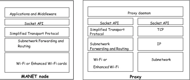
The legacy layered architecture provides a straightforward solution to the interconnection of ad hoc networks to the Internet. As opposite, the cross-layering approach is not a direct solution and opens several research issues. Before discussing these issues it is useful to present our view of the relationship between Internet and MANET. As shown in Figure 1.4, an ad hoc network can either operate in isolation (virtual community network) but can also be interconnected to the Internet through one (or more) Internet access router, i.e., a node that has both a wireless interface to participate to the ad hoc network and a wired interface that connects it to the Internet.
Wi-Fi or Enhanced Wi-Fi cards Subnetwork Forwarding and Routing
Simplified Transport Protocol Socket API
Applications and Middleware
Wi-Fi or Enhanced Wi-Fi Subnetwork
Forwarding and Routing Simplified Transport Protocol Socket API Proxy daemon Subnetwork IP TCP Socket API
MANET node Proxy
Figure 1.5: Interconnection to Internet: Proxy-based Architecture
In the former case using protocols specifically designed for MANET does not create any problem, while in the latter case solutions must be devised to compensate the differences between networking protocols in MANET and Internet. The easiest way, as shown in Figure 1.5 is to implement a proxy function on the Internet access router that compensates for the protocol differences. This is an effective solution that has already been proposed when wireless LANs are used to access the Internet, see the Indirect TCP model [BB97].
Wi-Fi or EnhancedWi-Fi cards Subnetwork Forwarding and Routing Simplified Transport Protocol
IP Socket API
Applications and Middleware
TCP
Figure 1.6: Interconnection to Internet: Ad hoc used as Subnetwork
In the case in which a proxy is not available, the ad hoc network can be seen from the Internet standpoint as a subnetwork technology (similarly to ATM, X.25, etc.) on top of which legacy TPC/IP protocols can be implemented. This is shown in Figure 1.6. Communications among MANET nodes are directly performed by exploiting the ad hoc network protocols, only. When, a node in the MANET needs to communicate with a remote Internet host, the ad-hoc-network
protocols are used to establish a “point-to-point” link between the ad hoc node and the Internet access router; on top of this link run the legacy TCP/IP protocols.
1.2.
Design Methods and Tools
In the next sections of this deliverable, we will present and evaluate the main directions taken in the MobileMAN project for re-designing the protocol stack to exploit the cross layering potentialities. As explained before, legacy protocol can still be used inside the MobileMAN architecture, for this reason we will also analyze the performance of legacy solutions emerging in the framework of the IEFT MANET WG.
Performance studies will be used to analyze and compare alternative solutions. There are two main approaches in system performance evaluation: the first uses measurements; the second is based on a representation of the system behavior via a model [L83] [KM88]. Measurement techniques are applied to real systems, and thus they can be applied only when a real system, or a prototype of it, is available. Currently, only few measurements studies on real ad hoc testbeds can be found in the literature, see e.g., [BMJ00][APE02].
Constructing a real ad hoc network test-bed for a given scenario is typically expensive and remains limited in terms of working scenarios, mobility models, etc. Furthermore, measurements are generally non-repeatable. For these reasons, protocols scalability, sensitiveness to users’ mobility patterns and speeds are difficult to investigate on a real testbed. Using a simulation or analytic model, on the other hand, permits the study of system behavior by varying all its parameters, and considering a large spectrum of network scenarios.
Evaluating system performance via a model consists of two steps: i) defining the system model, and ii) solving the model using analytical and/or simulative techniques. Analytical methods are often not detailed enough for the ad hoc networks evaluation and in terms of accounting for mobility, in their infancy. On the other hand, simulation modeling is a more standardized, mature, and flexible tool for modeling various protocols and network scenarios, and allows (by running the simulation model) data collection and analyses that fully characterize the protocol performance in most cases.
A very large number of simulation models have been developed to study ad hoc network architectures and protocols under many network scenarios (number of nodes, mobility rates, etc.). Simulation studies have been extensively applied for instance to compare and contrast large number of routing protocols developed for MANETs, see e.g., [JLHM99] [DCY00] [DPR00] [BMJHJ98]. [FS03] presents a theoretical framework to compare ad hoc-network routing protocols (in an implementation independent manner) by measuring each protocol’s performance relative to a theoretical optimum.
The use of simulation techniques in the performance evaluation of communication networks is a consolidated research area (see [CD99] and the references herein); however MANET simulation has several open research issues. An in depth discussion of methods and techniques for MANETs simulation can be found in [BB03c] [CCL03]; hereafter it is important to point one of the major problems in using simulation in MANET studies: the reliability of simulative results. Most MANET simulative studies are based on simulation tools. The main advantage of these tools is that they provide libraries containing pre-defined models for most communication protocols (e.g. 802.11, Ethernet, TCP, etc.). In addition, these tools often provide graphical interfaces that can be used both during the model development phase, and during simulation runs to simplify following dynamic protocol and network behaviors. Popular network simulators used in ad hoc networks include: OPNET [OPN], NS-2 [NS2], Glomosim [GLOM] and its commercial version QualNet [QUAL]. They all provide advanced simulation environments to test and debug different networking protocols, including collision detection modules, radio propagation and MAC protocols. Some recent results question however the validity of simulations based on these tools.
Specifically, [CSS02] presents the simulative results of the flooding algorithm using OPNET, NS-2 and Glomosim. Important divergences between the simulators results have been measured. The observed differences are not only quantitative (not the same absolute value), but also qualitative (not the same general behavior) making some past observation of MANET simulation studies an open issue. Similar problems have been observed, in the framework of the MobileMAN project, also by CNR researchers. Specifically, they compare and contrast the performance of two MANET routing protocols, DSR and AODV, by using NS-2 and Glomosim. Results obtained with the two simulators were often very (quantitative and qualitative) different [DC02].
0 100 200 300 400 500 600 700 800 900 0 100 200 300 400 500 600 700 800 900 pause (sec) DSR AODV NS-2 simulation throughput (kbps)
Figure 1.7: results of NS-2 simulator
GLOMOSIM simulation 0 100 200 300 400 500 600 700 800 900 0 100 200 300 400 500 600 700 800 900 pause (sec) DSR AODV throughput (kbps)
Figure 1.8: results of Glomosim simulator
An example of the obtained results is given in Figure 1.7 and Figure 1.8 showing the results obtained (in the same scenario) with NS-2 and Glomosim, respectively. Specifically, we considered an IEEE 802.11 network with 50 nodes moving according to the Random Waypoint mobility model in a 1500m x 300m closed rectangular area. The nodes maximum speed is equal to 1 m/sec. In the considered scenario there are 3 FTP sessions (1460 bytes per packet), and ten CBR sessions (512 bytes per packet). Figures 1.7 and 1.8 show the sum of the 3 FTP-session throughput
by varying the length of the pause in the Random Waypoint model.5 As it clearly appears from the
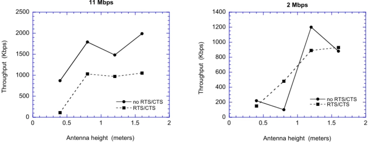
figures the obtained results are highly dependent on the simulation tool. For the above reasons, in this project we will use whenever possible measurement studies on real testbeds. Results from testbeds are also very important as they can point out problems that cannot be detected by simulation studies. For example, an important problem, related to the different transmission ranges for 802.11b control and data frames, is the so-called communication gray zones problem [LNT02]. The communication gray zone problem can not be revealed by most of commonly used simulation tools (e.g., NS-2, Glomosim) as in these 802.11 model both unicast and broadcast transmissions are performed at 2 Mbps, and hence have the same transmission range.
5 The length of each simulative experiment is equal to 900 seconds, hence a 900-second pause implies a static configuration, i.e., the nodes do not move during the experiment.
1.3.
References
[APE02] APE: Ad hoc Protocol Evaluation testbed. Department of Computer Systems at Uppsala, Sweden.
http://apetestbed.sourceforge.net/
[BB97] A. V. Bakre and B. R. Badrinath, “Implementation and performance evaluation of indirect TCP,” IEEE Trans. Computers, vol. 46, March 1997.
[BB03c] A. Boukerche, L. Bononi, “Simulation and Modeling of Wireless, Mobile and Ad Hoc Networks”, in Mobile Ad Hoc Networking, S. Basagni, M. Conti, S. Giordano, I. Stojmenovic (Editors), IEEE Press and John Wiley and Sons, Inc., New York, 2003.
[BMJ00] Josh Broch, David A. Maltz, David B. Johnson, “Quantitative Lessons From a Full-Scale Multi-Hop Wireless Ad Hoc Network Testbed”, Proceedings of the IEEE Wireless Communications and Network Conference 2000 (WCNC 2000).
[BMJHJ98] Josh Broch, David A. Maltz, David B. Johnson, Yih-Chun Hu, Jorjeta Jetcheva, “A Performance Comparison of Multi-Hop Wireless Ad Hoc Network Routing Protocols”, Proceedings of The Fourth Annual ACM/IEEE International Conference on Mobile Computing and Networking (MOBICOM '98), October 25-30, 1998, Dallas, Texas, USA.
[C00] M. Scott Corson, “A Triggered Interface” <draft-corson-triggered-00.txt>
[CP02] Jon Crowcroft, Ian Pratt, “Peer to Peer: Peering into the Future” in Advanced Lectures on Networking, Enrico Gregori, Giuseppe Anastasi, Stefano Basagni (Editors) LNCS 2497, 2002.
[CCL03] I. Chlamtac, M. Conti, and J. Liu, “Mobile Ad Hoc Networking: Imperatives and Challenges”, Ad Hoc Networks, No. 1(1) 2003.
[CD99] M. Conti, L. Donatiello, “Simulation modeling of local and metropolitan area networks”, Chapter 6 in Network Systems Design, E. Gelenbe, K. Bagchi, and G. Zobrist (Editors), Gordon & Breach, Amsterdam, 1999, pp. 117-142.
[CSS02] David Cavin, Yoav Sasson, Andrè Schiper, “On the Accuracy of MANET Simulators”, Proc. ACM POMC’02, Toulouse, France.October 2002,
[CZN02] K. Chen, S.H. Shah, K. Nahrstedt, “Cross-Layer Design for Data Accessibility in Mobile Ad Hoc Networks”, Wireless Personal Communications 21: 49–76, 2002
[CRVP01] K. Chandran, S. Raghunathan, S. Venkatesan, R. Prakash, “A Feedback Based Scheme for Improving TCP Performance in Ad Hoc Wireless Networks”, IEEE Personal Communication Magazine, Special Issue on Ad Hoc Networks, Vol. 8, N. 1, pp. 34-39, February 2001.
[DC02]. D. De Col, “Routing protocols for wireless ad hoc networks: performance evaluation of AODV and DSR”, Computer Science Laura Thesis, University of Pisa, October 2002 (in Italian).
[DCY00] S. R. Das, R. Castaneda, J. Yan, “Simulation Based Performance Evaluation of Mobile, Ad Hoc Network Routing Protocols”, ACM/Baltzer Mobile Networks and Applications (MONET) Journal, July 2000, pages 179-189.
[DPR00] Samir R. Das, Charles E. Perkins, Elizabeth M. Royer. "Performance Comparison of Two On-demand Routing Protocols for Ad Hoc Networks", Proceedings INFOCOM 2000, Tel Aviv, Israel, March 2000.
[FS03] Andras Farago, Violet Syrotiuk,,“MERIT: A Scalable Approach for Protocol Assessment”,
ACM/Kluwer MONET Vol. 8, No. 5 (Oct. 2003), Special issue on “Mobile Ad Hoc Network”, A.T. Campbell, M. Conti, S. Giordano (Editors).
[FZX03] Zhenghua Fu, Petros Zerfos, Kaixin Xu, Haiyun Luo, Songwu Lu, Lixia Zhang, Mario Gerla, “The Impact of Multihop Wireless Channel on TCP Throughput and Loss”, Proc. Infocom 2003, San Francisco, April 2003.
[GLOM] GloMoSim, Global Mobile Information Systems Simulation Library,
http://pcl.cs.ucla.edu/projects/glomosim/.
[GM01] R. Gold, C. Mascolo, “Use of Context-Awareness in Mobile Peer-to-Peer Networks”, in Proc. of the 8th IEEE Workshop on Future Trends of Distributed Computing Systems (FTDCS'2001), Bologna, Italy. October 2001.
[GW02] A.J. Goldsmith, S.B. Wicker, “Design Challenges for Energy-Constrained Ad Hoc Wireless Networks”, IEEE Wireless Communications, Volume 9, Number 4, August 2002. pp. 8- 27.
[HV02] Gavin Holland, Nitin H. Vaidya “Analysis of TCP Performance over Mobile Ad Hoc Networks”, ACM/Kluwer Journal of Wireless Networks 8(2-3), (2002) pp. 275-288.
[JLHM99] P. Johansson, T. Larsson, N. Hedman, B. Mielczarek “Routing Protocols for Mobile Ad-Hoc Networks – A Comparative Performance Analysis”, Proceedings of The Fifth Annual ACM/IEEE International Conference on Mobile Computing and Networking (MOBICOM '99), August 15-19, 1999, Seattle, Washington, USA. pp. 195-206.
[KK03] Vikas Kawadia, P.R. Kumar, "A Cautionary Perspective on Cross Layer Design", Submitted to IEEE Wireless Communication Magazine. July, 2003.
[KM88] J.F. Kurose, H. Mouftah, “Computer-Aided Modeling of Computer Communication Networks”, IEEE Journal on Selected Areas in Communications, Vol. 6, No. 1 (January, 1988), pp. 130-145.
[L83] S.S. Lavenberg, Computer Performance Handbook, Academic Press, New York, 1983.
[LNT02] H. Lundgren, E. Nordstron, C. Tschudin, “Coping with Communication Gray Zones in IEEE 802.11 based Ad Hoc Networks”, Proceedings of the ACM Workshop on Mobile Multimedia (WoWMoM 2002), Atlanta (GA), September 28, 2002, pp. 49-55.
[MC03] J.P. Macker, S. Corson, “Mobile Ad hoc Networks (MANET): Routing technology for dynamic, wirelessnetworking”, in MobileAd hoc networking, S.Basagni, M. Conti, S. Giordano, I. Stojmenovic (Editors), IEEE Press and John Wiley and Sons, Inc., New York, 2003.
[MCE02] Cecilia Mascolo, Licia Capra, Wolfgang Emmerich, “Middleware for Mobile Computing (A Survey)” in Advanced Lectures on Networking, Enrico Gregori, Giuseppe Anastasi, Stefano Basagni (Editors) LNCS 2497, 2002.
[MPR01] A. L. Murphy, G. P. Picco, G.-C. Roman, “Lime: A middleware for physical and logical mobility,” in Proceedings of the 21st International Conference on Distributed Computing Systems (ICDCS-21), Phoenix, AZ, USA, pp. 524–233, April 16-19 2001
[NS2] The Network Simulator - ns-2, http://www.isi.edu/nsnam/ns/index.html. [OPN] OPNET Modeler. http://www.opnet.com/products/modeler/home.html.
[YLA02] Wing Ho Yuen, Heung-no Lee, Timothy D. Andersen, “A Simple and Effective Cross Layer Networking System for Mobile Ad Hoc Networks”, Proc. of IEEE PIMRC, 2002.
2.
W
IRELESST
ECHNOLOGIESA mobile ad hoc network (MANET) represents a system of wireless mobile nodes that can freely and dynamically self-organize into arbitrary and temporary network topologies, allowing people and devices to seamlessly internetwork in areas without any pre-existing communication infrastructure. While many challenges remain to be resolved before large scale MANETs can be widely deployed, small scale, mobile ad hoc networks will soon appear. Network cards for single-hop ad hoc wireless networks are already available on the market, and these technologies constitute the building blocks to construct small scale ad-hoc network that extend the range of the single-hop wireless technologies to few kilometers.
As shown in Figure 2.1, we can classify ad hoc networks, depending on their coverage area, into several classes: Body (BAN), Personal (PAN), Local (LAN), Metropolitan (MAN) and Wide (WAN) area networks.
LAN WAN
~1m ~10m ~500m Range
BAN PAN MAN
20 - 50 Km
Figure 2.1: Ad Hoc Networks Taxonomy
The ad hoc network size in terms of the number of active nodes is the other metric used to classify MANETs. As defined in [MC03], we can classify the scale of an ad hoc network as small-scale (i.e., 2-20 nodes), moderate-scale (i.e., 20-100 nodes), large-scale (i.e., 100+ nodes), and very large-scale (i.e., 1000+ nodes). In [GK00], it was shown that in an ad hoc network with n nodes the per-node throughput is bounded byc n, where c is a constant. Unfortunately, experimental results [GGK01] indicate that with current technologies the per-node throughput decays as c' n1.68
and hence, with current technologies, only small- and moderate-scale can be implemented in an efficient way.
Wide- and Metropolitan-area ad hoc networks are mobile multi-hop wireless networks that present many challenges that are still to be solved (e.g., addressing, routing, location management, security, etc.), and their availability is not on immediate horizon. On the other hand, mobile ad hoc networks with smaller coverage can be expected to appear soon. Specifically, ad-hoc single-hop BAN, PAN and LAN wireless technologies are already common on the market [C03], and these technologies constitute the building blocks for constructing small/medium, multi-hop, ad hoc networks that extend their range over multiple radio hops [CMC99]. For these reasons, BAN, PAN and LAN technologies constitute the Enabling Technologies for ad hoc networking. A detailed discussion of Body, Personal, and Local Ad hoc Wireless Networks can be found in [C03]. Hereafter, the characteristics of these networks, and the technologies available to implement them, are summarized.
A body area network is strongly correlated with wearable computers. A wearable computer distributes on the body its components (e.g., head-mounted displays, microphones, earphones, etc.), and the BAN provides the connectivity among these devices. The communicating range of a BAN corresponds to the human body range, i.e., 1-2 meters. As wiring a body is generally cumbersome, wireless technologies constitute the best solution for interconnecting wearable devices.
Personal area networks connect mobile devices carried by users to other mobile and stationary devices. While a BAN is devoted to the interconnection of one-person wearable devices, a PAN is a network in the environment around the persons. A PAN communicating range is typically up to ten meters, thus enabling the interconnection of the BANs of persons close to each other, and the interconnection of a BAN with the environment around it.
The most promising radios for widespread PAN deployment are in the 2.4 GHz ISM band. Spread spectrum is typically employed to reduce interference and to increase bandwidth re-use.
Wireless LANs (WLANs) have a communication range typical of a single building, or a cluster of buildings, i.e., 100-500 meters. A WLAN should satisfy the same requirements typical of any LAN, including high capacity, full connectivity among attached stations, and broadcast capability. However, to meet these objectives, WLANs need to be designed to face some issues specific to the wireless environment, like security on the air, power consumption, mobility, and bandwidth limitation of the air interface [S96].
Two different approaches can be followed in the implementation of a WLAN: infrastructure-based
or ad hoc networking [S96]. An infrastructure-based architecture imposes the existence of a centralized controller for each cell, often referred to as Access Point. The Access Point (AP) is normally connected to the wired network, thus providing the Internet access to mobile devices. In contrast, an ad hoc network is a peer-to-peer network formed by a set of stations within the range of each other, which dynamically configure themselves to set up a temporary network. In the ad hoc configuration, no fixed controller is required, but a controller may be dynamically elected among the stations participating in the communication.
The success of a network technology is connected to the development of networking products at a competitive price. A major factor in achieving this goal is the availability of appropriate networking standards. Currently, two main standards are emerging for ad hoc wireless networks: the IEEE 802.11 standard for WLANs [IEEE802], and the Bluetooth specifications6 [BLU] for
short-range wireless communications [B01][BLU01][MB00]. In addition to the IEEE standards, the European Telecommunication Standard Institute (ETSI) has promoted the HiperLAN (HIgh Performance Radio Local Area Network) family of standards for WLANs [ETSI]. Among these, the most interesting standard for WLAN is HiperLAN/2. The HiperLAN/2 technology addresses high-speed wireless network with data rates ranging from 6 to 54 Mbit/s. Infrastructure-based and ad hoc networking configurations are both supported in HiperLAN/2.To a large degree, HiperLAN is still at the prototype level, and hence we will not consider it more in detail. More details on this technology can be found in [EM02]. [ZD03]surveys the off-the-shelf technologies for constructing ad hoc networks.
Due to its extreme simplicity, the IEEE 802.11 standard is a good platform to implement a single-hop WLAN ad hoc network. Furthermore, multi-single-hop networks covering areas of several square kilometers can potentially be built by exploiting the IEEE 802.11 technology. Currently, the widespread use of IEEE 802.11 cards makes this technology the most interesting off-the-shelf enabler for ad hoc networks. For this reason in the MobileMAN project we use 802.11 as the reference technology.
The IEEE 802.11 standard defines two operational modes for WLANs: infrastructure-based and
infrastructure-less or ad hoc. Network interface cards can be set to work in either of these modes but not in both simultaneously. The infrastructure-based is the mode commonly used to construct the so called Wi-Fi hotspots, i.e., to provide wireless access to the Internet. The standardization efforts concentrated on solutions for infrastructure-based WLANs, while little or no attention was given to the ad hoc mode. This section is therefore devoted to an in-depth investigation of the ad hoc features of the IEEE 802.11 standard to study its effectiveness to construct ad hoc networks,
and to propose and investigate solutions for enhancing this technology for a better support of the ad hoc networking paradigm.
2.1.
IEEE 802.11 Architecture and Protocols
In 1997, the IEEE adopted the first wireless local area network standard, named IEEE 802.11, with data rates up to 2Mbps [IEEE97]. Since then, several task groups (designated by the letters from a,
b, c, etc.) have been created to extend the IEEE 802.11 standard. The task groups 802.11b and 802.11a have completed their work by providing two relevant extensions to the original standard [IEEE802]. The 802.11b task group produced a standard for WLAN operations in 2.4 GHz band that extends IEEE 802.11 to data rates up to 11 Mbps. This standard, published in 1999, has been very successful. Currently, there are several IEEE 802.11b products available on the market. The 802.11a task group created a standard for WLAN operations in the 5 GHz band, with data rates up to 54 Mbps. Among the other task groups, it is worth mentioning the task group 802.11e (that attempts to enhance the MAC with QoS features to support voice and video over 802.11 networks), and the task group 802.11g that has just defined a higher speed extension to the 802.11b.
Currently, IEEE 802.11b, which is also known with the friendly name of Wireless Fidelity (Wi-Fi), is the de-facto reference technology for wireless LAN networks. For this reason hereafter we will focus on the IEEE 802.11 architecture and protocols as defined in the original standard [IEEE97], and then we will emphasize the differences between the 802.11b standard with respect to the original 802.11 standard. Physical Layer contention free services contention services Distributed Coordination Function Point Coordination Function
Figure 2.2: IEEE 802.11 Architecture
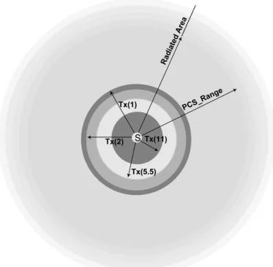
The IEEE 802.11 standard specifies both the MAC layer and the Physical Layer (see Figure 2.2). The MAC layer offers two different types of service: a contention-based service provided by the
Distributed Coordination Function (DCF), and a contention-free service implemented by the Point Coordination Function (PCF). These service types are made available on top of a variety of physical layers. Specifically, three different technologies have been specified in the standard: Infrared (IF), Frequency Hopping Spread Spectrum (FHSS) and Direct Sequence Spread Spectrum (DSSS).
The DCF provides the basic access method of the 802.11 MAC protocol and is based on a Carrier Sense Multiple Access with Collision Avoidance (CSMA/CA) scheme. The PCF is implemented on top of the DCF and is based on a polling scheme. It uses a PointCoordinator that cyclically polls stations, giving them the opportunity to transmit. Since the PCF can not be adopted in ad hoc mode, it will not be considered hereafter.
2.1.1.
Distributed Coordination Function (DCF)
According to the DCF, before transmitting a data frame, a station must sense the channel to determine whether any other station is transmitting. If the medium is found to be idle for an interval longer than the Distributed InterFrame Space (DIFS), the station continues with its
transmission7 (see Figure 2.3). On the other hand (i.e., if the medium is busy), the transmission is
deferred until the end of the ongoing transmission. A random interval, henceforth referred to as the
backoff time, is then selected, which is used to initialize the backoff timer. The backoff timer is decreased for as long as the channel is sensed as idle, stopped when a transmission is detected on the channel, and reactivated when the channel is sensed as idle again for more than a DIFS (for example, the backoff timer of Station 2 in Figure 2.3 is disabled while Station 3 is transmitting its frame; the timer is reactivated a DIFS after Station 3 has completed its transmission). The station is enabled to transmit its frame when the backoff timer reaches zero. The backoff time is slotted. Specifically, the backoff time is an integer number of slots uniformly chosen in the interval (0,
CW-1). CW is defined as the Backoff Window, also referred to as Contention Window. At the first transmission attempt CW=CWmin, and it is doubled at each retransmission up to CWmax. In the standard CWmin and CWmax values depend on the physical layer adopted. For example, for the FHSS Physical Layer Cwmin and Cwmax values are 16 and 1024, respectively [IEEE97].
Station 1 Station 2 Station 3 FRAME DIFS FRAME FRAME DIFS DIFS Packet Arrival Frame Transmission
Elapsed Backoff Time Residual Backoff Time
Figure 2.3. Basic Access Mechanism
Obviously, it may happen that two or more stations start transmitting simultaneously, and hence a collision occurs. In the CSMA/CA scheme, stations are not able to detect a collision by hearing their own transmissions (as in the CSMA/CD protocol used in wired LANs). Therefore, an immediate positive acknowledgement scheme is employed to ascertain the successful reception of a frame. Specifically, upon reception of a data frame, the destination station initiates the transmission of an acknowledgement frame (ACK) after a time interval called Short InterFrame Space (SIFS). The SIFS is shorter than the DIFS (see Figure 2.4) in order to give priority to the receiving station over other possible stations waiting for transmission. If the ACK is not received by the source station, the data frame is presumed to have been lost, and a retransmission is scheduled. The ACK is not transmitted if the received packet is corrupted. A Cyclic Redundancy Check (CRC) algorithm is used for error detection.
After an erroneous frame is detected (due to collisions or transmission errors), a station must remain idle for at least an Extended InterFrame Space (EIFS) interval before it reactivates the backoff algorithm. Specifically, the EIFS shall be used by the DCF whenever the physical layer has indicated to the MAC that a frame transmission was begun that did not result in the correct reception of a complete MAC frame with a correct FCS value. Reception of an error-free frame during the EIFS re-synchronizes the station to the actual busy/idle state of the medium, so the EIFS is terminated and normal medium access (using DIFS and, if necessary, backoff) continues following reception of that frame.
7To guarantee fair access to the shared medium, a station that has just transmitted a packet and has another packet ready for transmission must perform the backoff procedure before initiating the second transmission.
Source Station Destination Station FRAME DIFS SIFS ACK Packet Arrival
Figure 2.4: The SIFS is shorter than the DIFS
2.1.2.
Common Problems in Wireless Ad Hoc Networks
In this section we discuss some problems that can arise in wireless networks, mainly in the ad hoc mode. The characteristics of the wireless medium make wireless networks fundamentally different from wired networks. Specifically, as indicated in [IEEE97]:
- the wireless medium has neither absolute nor readily observable boundaries outside of which stations are known to be unable to receive network frames;
- the channel is unprotected from outside signals;
- the wireless medium is significantly less reliable than wired media;
- the channel has time-varying and asymmetric propagation properties.
In a wireless (ad hoc) network that relies upon a carrier-sensing random access protocol, like the IEEE 802.11 DCF protocol, the wireless medium characteristics generate complex phenomena such as the hidden-station and exposed-station problems.
Figure 2.5 shows a typical “hidden station” scenario. Let us assume that station B is in the transmitting range of both A and C, but A and C cannot hear each other. Let us also assume that A is transmitting to B. If C has a frame to be transmitted to B, according to the DFC protocol, it senses the medium and finds it free because it is not able to hear A’s transmissions. Therefore, it starts transmitting the frame but this transmission will result in a collision at the destination Station B.
A B C
Figure 2.5: The “hidden station” problem
The hidden station problem can be alleviated by extending the DCF basic mechanism by a virtual carrier sensing mechanism (also referred to as floor acquisition mechanism) that is based on two control frames: Request To Send (RTS) and Clear To Send (CTS), respectively. According to this mechanism, before transmitting a data frame, the station sends a short control frame, named RTS, to the receiving station announcing the upcoming frame transmission (see Figure 2.6). Upon receiving the RTS frame, the destination station replies by a CTS frame to indicate that it is ready to receive the data frame. Both the RTS and CTS frames contain the total duration of the transmission, i.e., the overall time interval needed to transmit the data frame and the related ACK. This information can be read by any listening station that uses this information to set up a timer called Network Allocation Vector (NAV). While the NAV timer is greater than zero the station must
refrain from accessing the wireless medium. By using the RTS/CTS mechanism, stations may become aware of transmissions from hidden station and on how long the channel will be used for these transmissions. Source Station Destin. Station Another Station FRAME DIFS SIFS DIFS SIFS SIFS ACK RTS CTS Backoff Time NAV RTS NAV CTS
Figure 2.6: Virtual Carrier Sensing mechanism
Figure 2.7 depicts a typical scenario where the “exposed station” problem may occur. Let us assume that both Station A and Station C can hear transmissions from B, but Station A can not hear transmissions from C. Let us also assume that Station B is transmitting to Station A and Station C receives a frame to be transmitted to D. According to the DCF protocol, C senses the medium and finds it busy because of B’s transmission. Therefore, it refrains from transmitting to C although this transmission would not cause a collision at A. The “exposed station” problem may thus result in a throughput reduction.
D B
A C
Figure 2.7: The “exposed station” problem
2.1.3.
Ad Hoc Networking Support
In this section we will describe how two or more 802.11 stations set up an ad hoc network. In the IEEE 802.11 standard, an ad hoc network is named Independent Basic Service Set (IBSS). An IBSS enables two or more 802.11 stations to communicate each other without the intervention of either a centralized AP, or an infrastructure network. Hence, the IBSS can be considered as the support provided by the 802.11 standard for mobile ad hoc networking.8
Due to the flexibility of the CSMA/CA protocol, to receive and transmit data correctly it is sufficient that all stations within the IBSS are synchronized to a common clock. The standard specifies a Timing Synchronization Function (TSF) to achieve clock synchronization between stations. In an infra-structured network the clock synchronization is provided by the AP and all
8 To uniquely identify a IBSS it is necessary to associate to it an identification number (IBSSID) that is locally administered and that will be used by any other Station to join the IBSS, i.e., the ad hoc network. When a station starts a new IBSS, it generates a 46-bit random number in a manner that minimizes the probability that the same number is generated by another station.
stations synchronizes their own clock to the AP’s clock. In an IBSS, due to the lack a centralized station, clock synchronization is achieved through a distributed algorithm. In both cases synchronization is obtained by transmitting special frames, called beacons, containing timing information.
The TSF requires two fundamental functionalities, namely synchronization maintenance and
synchronization acquirement, that will be sketched below. We only focus on IBSS.
Synchronization maintenance
Each station has a TSF timer (clock) with modulus 264 counting in increments of microseconds.
Stations expect to receive beacons at a nominal rate defined by the BeaconPeriod parameter. This parameter is decided by the station initiating the IBSS, and is then used by any other station joining the IBSS. Stations use their TSF timers to determine the beginning of beacon intervals or periods. At the beginning of a beacon interval each station performs the following procedure:
- it suspends the decrementing of the backoff timer for any pending (non-beacon) transmission;
- it generates a random delay interval uniformly distributed in the range between zero and twice the minimum value of the Contention Window.
- it waits for the random delay;
- if a beacon arrives before the random delay timer has expired, it stops the random delay timer, cancel the pending beacon transmission, and resumes the backoff timer;
- if the random delay timer has expired and no beacon has been received, it sends a beacon frame.
The sending station sets the beacon timestamp to the value of its TSF timer at the time the beacon is transmitted. Upon reception of a beacon, the receiving station looks at the timestamp. If the beacon timestamp is later than the station’s TSF timer, the TSF timer is set to the value of the received timestamp. In other words, all stations within the IBSS synchronize their TSF timer to the quickest TSF timer.
Synchronization acquirement
This functionality is necessary when a station wants to join an already existing IBSS. The discovery of existing IBSSs is the result of a scanning procedure of the wireless medium during which the station receiver is tuned to different radio frequencies, looking for particular control frames. Only if the scanning procedure does not result in finding any IBSS, the station may start with the creation of a new IBSS. The scanning procedure can be either passive or active.
In a passive scanning the station listens to the channels for hearing a beacon frame. It is worth reminding that a beacon frame contains not only timing information for synchronization, but also the complete set of IBSS parameters. This set includes the IBSS identifier IBSSID, the BeaconPeriod parameter, the data rates that can be supported, the parameters relevant to IBSS management functions (e.g., power saving management).
Active scanning involves the generation of Probe frames, and the subsequent processing of received Probe Response frames. The station that decides to start an active scanning procedure has a ChannelList of radio frequencies that will be scanned during the procedure. For each channel to be scanned a probe with broadcast destination is sent by using the DCF access method. At the same time a ProbeTimer is started. If no response to the probe is received before the ProbeTimer reaches the MinChannelTime the next channel of the list is considered. Otherwise, the station continues to scan the same channel until the timer reaches the MaxChannelTime. Then, the station processes all received Probe responses.
Probe responses are sent using normal frame transmission rules as directed frames to the address of the station that generated the Probe request. In an IBSS, only the station that generated the last beacon transmission will respond to a probe request, in order to avoid the waste of bandwidth with repetitive control frames. In each IBSS, at least one station must be awake at any given time to respond to Probe request. Therefore, the station that sent the last beacon remains in the awake state in order to respond to Probe requests, until a new beacon is received. There may be more than one station in a IBSS that responds to a given probe request, particularly in the case where more than one station transmitted a beacon, either due to not receiving successfully a previous beacon, or due to collision between beacon transmissions.
2.1.4.
Power Management
In a mobile environment, portable devices have limited energetic resources since they are powered through batteries. Power management functionalities are thus extremely important both in the infrastructure-based and in the ad hoc modes. Obviously, in the ad hoc mode, i.e., inside an IBSS, Power Saving (PS) strategies need to be completely distributed in order to preserve the self-organizing nature of the IBSS. A station may be in one of two different power states: awake
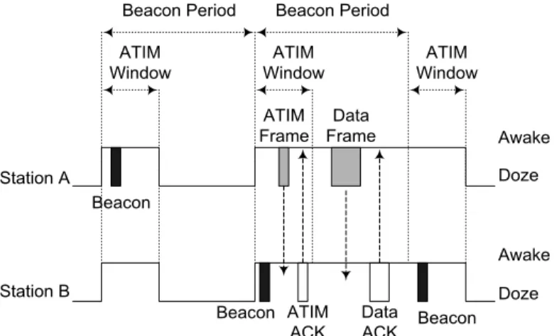
(station is fully powered) or doze (the station is not able to transmit or receive). Multicast and/or directed frames destined to a power-conserving station are first announced during a period when all stations are awake. An Ad hoc Traffic Indication Map (ATIM) frame does the announcement. A station operating in the PS mode listens to these announcements and, based on them, decides whether it has to remain awake or not.
ATIM frames are transmitted during the ATIM Window, a specific period of time following the beginning of a Beacon period whose length is defined by the ATIMWindow parameter (an IBSS parameter included in the beacon content). During the ATIM Window, only beacon and ATIM frames can be exchanged and all stations must remain awake. Directed ATIM frames are to be acknowledged by the destination station, while multicast ATIMs are not to be acknowledged. Hence a station sends a directed ATIM frame and waits for the acknowledgement. If this acknowledgement does not arrive it executes the backoff procedure for re-transmitting the ATIM frame.
A station receiving a directed ATIM frame must send the acknowledgement and remain awake for the entire duration of the beacon interval, waiting for the announced data frame. Data frames are transmitted at the end of the ATIM Window according to the DCF access method (see Figure 2.8). If a station does not receive any ATIM frame during the ATIM Window it, can enter the doze state at the end of the ATIM window.
Beacon Beacon
Beacon
Beacon Period Beacon Period
ATIM Window ATIM Window ATIM Window ATIM Frame Data Frame Data ACK ATIM ACK Station A Station B Awake Doze Awake Doze
Figure 2.8: A data exchange between stations operating in PS mode in an ad hoc
network
2.1.5.
IEEE802.11and IEE802.11b
The 802.11b standard extends the 802.11 standard by introducing a higher-speed Physical Layer in the 2.4 GHz frequency band still guaranteeing the interoperability with 802.11 cards. Specifically, 802.11b enables transmissions at 5.5 Mbps and 11 Mbps, in addition to 1 Mbps and 2 Mbps. 802.11b cards may implement a dynamic rate switching with the objective of improving performance. To ensure coexistence and interoperability among multirate-capable stations, and with 802.11 cards, the standard defines a set of rules that must be followed by all stations in a WLAN. Specifically, for each WLAN is defined a basic rate set that contains the data transfer rates that all stations within the WLAN will be capable of using to receive and transmit.
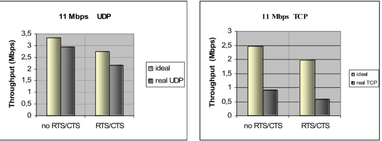
To support the proper operation of a WLAN, all stations must be able to detect control frames. Hence, RTS, CTS, and ACK frames must be transmitted at a rate included in the basic rate set. In addition, also frames with multicast or broadcast destination addresses must be transmitted at a rate belonging to the basic rate set. These differences in the rates used for transmitting (unicast) data and control frames have a big impact on the system behavior as clearly pointed out in [E02]. Our experimental results presented below show the impact of different transmission rates on the IEEE 802.11b behavior.
2.2.
Analysis of 802.11 performance
Two main performance indices are used to analyze the performance of a technology for wireless LANs: the throughput and the delay.
As far as throughput is concerned, a special attention will be deserved to the Medium Access Control (MAC) protocol capacity ([KSY84], [CGL97]) defined as: the maximum fraction of channel bandwidth used by successfully transmitted messages. This performance index is important as wireless networks deliver much lower bandwidth than wired networks, e.g. 1-11 Mbps vs. 100-1000 Mbps [S96]. Since a WLAN relies on a common transmission medium, the transmissions of the network stations must be coordinated by the MAC protocol. This coordination can be achieved by means of control information that is carried explicitly by control messages traveling along the medium (e.g. ACK messages), or can be provided implicitly by the medium itself using the carrier sensing to identify the channel being either active or idle. Control messages, or message retransmissions due to collision, remove channel bandwidth from that available for successful message transmission. Therefore, the capacity gives a good indication of the overheads required by the MAC protocol to perform its coordination task among stations, or in other words of the effective bandwidth that can be used on a wireless link for data transmission.
The delay can be defined in several forms (access delay, queuing delay, propagation delay, etc.) depending on the time instants considered during its measurement, see [CGL97]. In computer networks the response time (i.e., the time between the generation of a message at the sending station, and its reception at the destination station) is the best figure to measure the Quality of Service (QoS) perceived by the users. However, the response time depends on the amount of buffering inside the network, and it is not always meaningful to evaluate a LAN technology. For example, during congested periods, the buffers fill up, and thus the response time does not depend on the LAN technology but it is mainly a function of the buffer length. For this reason, hereafter, the MAC delay index is used. The MAC delay of a station in a LAN is defined as: the time between the instant at which a packet comes to the head of the station transmission queue and the end of the packet transmission [CGL97].
2.2.1.
802.11 Protocol Capacity
The IEEE 802.11 protocol capacity was extensively investigated in [CCG00]. Hereafter, the main results of that analysis are summarized. In [CCG00] to study the protocol capacity it was defined a
p-persistent IEEE 802.11 protocol. This protocol differs from the standard protocol only in the selection of the backoff interval. Instead of the binary exponential backoff used in the standard, the backoff interval of the p-persistent IEEE 802.11 protocol is sampled from a geometric distribution with parameter p. Furthermore, in [CCG00], it was shown that a p-persistent IEEE 802.11 protocol closely approximates the standard protocol with the same average backoff window size. By developing an analytical model for the p-persistent IEEE 802.11 protocol, in [CCG00] it is derived the p value corresponding to the theoretical upper bound, i.e. the p value (pmin) that maximizes the capacity of the p-persistent IEEE 802.11 protocol. Due to the correspondence (from the capacity standpoint) between the standard protocol and the p-persistent one, the theoretical upper bound constitutes also a throughput limit for tuning the IEEE 802.11 protocol. Specifically, the throughput limit is achieved by an IEEE 802.11 protocol whose average backoff window size (hereafter, optimal average backoff window size) is equal to the average backoff of the p-persistent IEEE 802.11 protocol using the optimal p value, pmin.
#
#
#
#
empty slots
collision
successful
transmission
DIFS
collision
DIFS
Virtual transmission time
Figure 2.9: Structure of a virtual transmission time
In the following, for ease of reading, we briefly summarize the procedure used to derive the pmin value. For more details see [CCG00]. The IEEE 802.11 MAC protocol capacity is analytically estimated by developing a model with a finite number, M, of stations operating in asymptotic conditions. This means that all the M network stations always have a packet ready for transmission. The computation of the protocol capacity, presented in [CCG00], is performed by observing the system at the end of each successful transmission assuming that packet lengths are i.i.d. random variables sampled from a