Purdue e-Pubs
International Refrigeration and Air Conditioning
Conference
School of Mechanical Engineering
2010
Payback Period Estimation of Ground-Source and
Air-Source Multi Heat Pumps in Korea Based on
Yearly Running Cost Simulation
Noma Park
LG ElectronicsSeung-Hyun Jung
LG ElectronicsHee-Woong Park
LG ElectronicsHwan-Jong Choi
LG ElectronicsSimon Chin
LG ElectronicsSee next page for additional authors
Follow this and additional works at:
http://docs.lib.purdue.edu/iracc
Park, Noma; Jung, Seung-Hyun; Park, Hee-Woong; Choi, Hwan-Jong; Chin, Simon; and Jung, Hoon, "Payback Period Estimation of Ground-Source and Air-Source Multi Heat Pumps in Korea Based on Yearly Running Cost Simulation" (2010).International Refrigeration and Air Conditioning Conference.Paper 1146.
Payback Period Estimation of Ground-Source and Air-Source Multi Heat Pumps in Korea
Based on Yearly Running Cost Simulation
Noma PARK
1*, Seung-Hyun JUNG
1, Hee-Woong PARK
1, Hwan-Jong CHOI
1, Simon CHIN
1,
and Hoon JUNG
21
LG Electronics Inc., Corporate Air Conditioning R&D Laboratory
327-23, Gasan-Dong, Geumcheon-Gu, Seoul, 153-802, Korea
Phone: +82-55-260-3860, e-Mails:
,
[email protected]
,
,
,
2
Korea Electric Power Research Institute,
Munji-Ro 65, Yusung-Gu, Daejeon, 305-380, Korea
Phone: +82-42-865-5114, e-Mail:
* Corresponding Author
ABSTRACT
In this study, we compute yearly running cost of air- and ground-source multi heat pump for space cooling, floor heating, and domestic hot water. From computed yearly running cost, payback period was computed when they replace the gas-fired boiler and air-conditioner combination. Toward accurate running cost simulation, we develop an in-house simulation code that integrates heat pump performance, realistic floor heating, space cooling by indoor units, and hot water storage tank. Annual running cost is computed by integrating input power consumption by the compressor and pumps based on detailed hourly outdoor temperature data of Seoul and domestic hot water usage pattern. It is shown that the annual running costs of ground- and air-source heat pumps are, respectively, 20~45%, and 56% of that of boiler and air conditioner, and that the payback periods are from 3.0 to 15 years depending on the progressive electricity tax, subsidy level for the installation cost, and discharge water temperature control method.
1. INTRODUCTION
Heat pumps are considered as promising alternatives to gas/oil-fired boiler in the sense that they do not use fossil fuels, and that they are highly efficient and thus emit less CO2 than boilers. It is especially true to a number of EU
countries, where heat pumps already take non-negligible portion in the local heating market thanks to substantial incentives and subsidies. However, heat pumps are not yet accepted as residential heating solution in Korea due to unacceptably high initial cost and the progressive tax in the electricity cost. In addition, for the case of ground source heat pump (denoted as GSHP hereinafter), borehole construction cost is insurmountably high to overwhelm all other economic merits of GSHP (Figure 1).
Very recently, these hurdles are being removed by the government drafting energy policies favorable to heat pumps. The most important change is the subsidies and exemption of the progressive tax in electricity bill for products using renewable energy, which is the case with GSHP. Now the price of electricity per kWh is comparable to that of gas so that the running cost competition with boiler becomes simply the matter of COP. However, since air-source heat pumps (denoted as ASHPs) are not regarded as renewable energy product, ASHP should prove its own
competitiveness without subsidy purely based on its low energy consumption and relatively low initial cost as compared to GSHP.
Figure 1: Initial cost (product + installation) comparison between boiler + air conditioner and multi heat pumps in Korea. Here, costs are in US dollar.
The main objectives of the present study are 1) to elucidate the economic viability of GSHP and ASHP by taking the above mentioned environmental changes into consideration, 2) to find the optimal control logic to maximize energy saving, and 3) to find insight into appropriate amount of subsidy for heat pumps and reasonable electricity tariff system. To this end one needs an accurate annual simulation tool for the realistic estimation of energy consumption and dynamic response of heat pumps to surroundings.
Toward accurate running cost simulation, we develop an in-house simulation code that integrates heat pump cycle, realistic floor heating, space cooling/heating by in-door units (IDUs), hot water storage tank. For heat pump cycle simulation, compressors and heat exchangers are modeled by regression fit of experimental data. In order to calculate instantaneous room temperature, simplified model for each zone with IDU is combined with analytic solution of heat equation on the surface of floor with hot water flowing underneath. One-dimensional water/thermal storage tank model is developed to account for the stratification effect.
This paper is organized as follows: In section 2, we describe the main characteristics of ASHP and GSHP considered in this study. Governing equation, numerical method, floor heating simulation method, outdoor temperature and hot water usage pattern are given in Section 3. Simulation results and running cost estimation is performed in Section 4, and the summary and conclusions are given in Section 5.
2. MULTI HEAT PUMPS
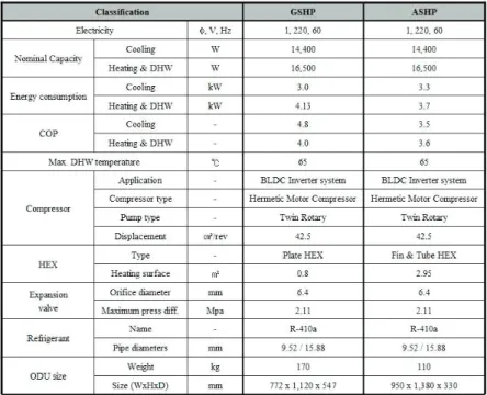
GSHP considered in this study is an all-in-one type multi inverter heat pump with single outdoor unit that contains three water-refrigerant heat exchangers (HEXs), which are for ground water, floor heating, and domestic hot water, respectively. It adopts 5hp inverter compressor, whose nominal cooling and heating capacities are 14.5 kW and 16 kW, respectively. See Table 1 for more details on the specification of GSHP. The schematics of GSHP operation scene is depicted in Figure 2. As shown in Figure 2, indoor units (IDUs) are used for space cooling, and floor heating is considered instead of heating by IDUs since the floor heating is close to traditional ‘Ondol’ heating and, thus, is the most preferred heating option in Korea. The nominal domestic hot water (DHW) capacity is 5kW and DHW at specified temperature is achieved by the mixing valve. The size of the sanitary tank is 200 liter, which is large enough to cover averaged daily hot water demand.
Table 1: Specification of GSHP and ASHP
Figure 2: Schematics on main functionality of ground source heat pump.
As shown in Table 2, the specification of ASHP is basically similar to GSHP except that it adopts fin-tube HEX instead of ground HEX, and that ASHP is a split-type one that has IDU called hydro-kit having water-refrigerant for floor heating and DHW (Figure 3).
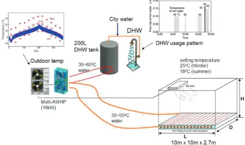
Figure 3: A simplified model for running cost simulation of ASHP
3. YEARLY RUNNING COST SIMULATION
In this section, yearly running cost simulation methodology is summarized including system configuration, governing equations, discretization method, outdoor temperature, floor heating simulation, and sanitary tank simulation.
3.1 System configuration and governing equations
As shown in Figure 3 for ASHP system, we consider a simplified model house with 10m (L) by 10m (D) by 2.7m (H) size, and a 0.5m diameter, 200 liter sanitary tank. We also consider the same installation scene for GSHP. In order to simplify the simulation only one IDU and single zone is considered. However, this approach can be easily expanded to multi-zone simulation. The main purpose of this simulation is to run heat pumps to maintain setting indoor and sanitary tank temperature as actual heating/cooling system does, and to measure corresponding energy consumption.
Indoor and sanitary tank temperature are assumed to obey the following lumped and one-dimensional energy equation
(
)
,,air id floor IDU id house id od p id dt Q Q h A T T dT C m = − − − (1)
(
)
, ) ( 2 2 ,w ST ST ST hp ST ST ST ST od p w h T T z T kA z q z T u t T A C − ℘ − ∂ ∂ + = ¸ ¹ · ¨ © § ∂ ∂ + ∂ ∂ ρ (2)Where Tid, TST, and TOD are, respectively, temperatures of indoor, sanitary tank and outdoor. Qfloor, QIDU, and )
(z
qhp denote heat capacity given by floor heating, IDU cooling and internal HEX of sanitary tank, respectively, where z denotes coordinate direction of tank height. mid =ρairVhouse is the weight of indoor air, Ahouse the surface area of the house, AST the cross sectional area of sanitary tank, and ℘ the perimeter of the sanitary tank. hid and
ST
h , respectively, are heat loss coefficients of house and sanitary tank. Since loss coefficients play the crucial role in the determination of thermal load, as is evident from equations (1) and (2), the energy consumption is highly dependent upon the choice of these values. Computational parameters including loss coefficients and operational conditions of HPs are summarized in Table 2.
Table 2: Conditions for yearly running cost simulation
Since energy consumption by DHW takes relatively small portion in the total energy consumption, equation (2) can be replaced by a lumped one like equation (1) without causing significant error. However, one-dimensional system is preferred to accurately see the effect of stratification on the energy consumption. For the spatial discretization of (2), third-order upwind difference and second order central difference are adopted for convection and diffusion terms, respectively. A special care should be given to the boundary conditions of equation (2), since the inlet and outlet mixing has significant impact on the temperature distribution. We followed the definition of mixing parameter derived by Nelsol et al. (1998) for boundary conditions.
Since inverter compressor is adopted cooling and heating capacities are subject to change according to cooling and thermal loads. The control logic for changing capacities will be explained later. In order to compute required power input for given heat capacity and outdoor/indoor conditions, one can numerically simulate heat pump based on models on compressor, evaporator, condenser and expansion devices (see, e.g. Zhao et al., 2003). However, such a detailed numerical simulation is not appropriate for the present annual running cost simulation due to significant computational overhead. Instead, for a given inverter cooling load and external conditions, power input or coefficient of performance (COP) for ASHP is given by the following regression fit:
IDU od
id
cooling c cT cT cQ
COP = 0+ 1 + 2 + 3 , (3)
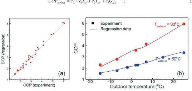
Figure 4: Heating COP of ASHP at various conditions: (a) joint PDF between experimental data and second order regression fit; (b) COP at various outdoor and water temperature conditions at nominal heat capacity.
, 9 8 7 2 6 5 2 4 3 2 2 1
0 w w od od IDU IDU w od w IDU od IDU
heating h hT hT hT hT hQ hQ hT T hT Q hT Q
COP = + + + + + + + + + (4)
where coefficients h0~h9 are again determined from the least-square fit of experimental data. For the case of heating, second order regression is considered as first order regression showed non-negligible scatter with
experimental data. Figure 4 shows heating COPs given by equation (4) and experimental data. As shown by Figure 4(b), COP is strongly dependent upon outdoor temperature and water temperature, since they have strong correlation with evaporating and condensing temperatures, respectively. COP of DHW takes the same form as equation (4) with different coefficients. For GSHP, COP is indirectly influenced by outdoor temperature, but is governed by water temperature of ground HEX. Thus, the outdoor temperature Tod in the regression fits (3) and (4) is replaced the ground HEX water temperature.
For the temporal integration of (1) and (2), 4th order Runge-Kutta method is applied at fixed time step t
Δ = 60 sec = 1 min, and the integration is carried out for a year, or for 365×24×60 = 525,600 time steps. Once we know heating capacity, for example, and corresponding COP the energy consumption during a specified period is readily
computed by
³
= 2 1 . ) ~ (1 2 t t heating heating heating dt COP Q t t E (5)Energy consumption by cooling and DHW can be computed in the same way.
3.2 Outdoor temperature, daily hot water consumption, and ground HEX temperature
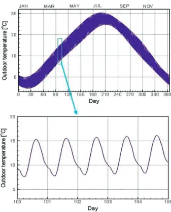
For the running cost simulation described in the previous section, one needs outdoor temperature data and daily hot water consumption amount and detailed usage pattern. For outdoor temperature, we adopt published data for weather data at Seoul (Kim and Kim, 2003), given by the following series form:
. 365 2 sin ) ( 365 2 cos ) ( ) , ( 3 0
¦
= »¼ º « ¬ ª ¸ ¹ · ¨ © § + ¸ ¹ · ¨ © § = n n n d n h B d n h A h d T π π (6)Since this data is given at each hour for a complete year, linear interpolation is used to obtain minute-by-minute data. A complete hourly plot of equation (6) is given in Figure 5. For daily hot water usage pattern, we adopt a standard JRA data for DHW (Yokoyama et al., 2010) as shown in Figure 6. Change of daily DHW usage is modeled by multiplying constant factors to the pattern shown in Figure 6. In this study, 270 liter of daily hot water consumption is assumed throughout a year.
On the other hand, the efficiency of GSHP is directly influenced by the soil temperature, which is the function of borehole depth and outdoor temperature (Kasuda and Archenbach, 1965):
, 365 2 365 2 cos 365 exp ) , ( 5 . 0 5 . 0 » » ¼ º « « ¬ ª °¿ ° ¾ ½ °¯ ° ® ¸ ¹ · ¨ © § − − » » ¼ º « « ¬ ª ¸ ¹ · ¨ © § − − = α π π α π t t z z T T t z
Tsoil mean amp shift (7)
where Tmean is the mean surface temperature (average air temperature), Tamp is the amplitude of surface temperature,
and Tshift is the day of the year of the minimum surface temperature. They are given by equation (6), the outdoor
temperature data. α is the thermal diffusivity of the soil. In this study, we assume the U type vertical borehole whose depth is 100m. Then, local ground HEX temperature TGH is determined by the conductive and convective heat transfer with soil. The thermal resistance of soil can be calculated using the linear source theory or cylindrical source theory, while that inside the borehole is more complicated due to the integrated resistance of fluid convection, and the conduction through pipe and grout (Liu et al., 2009). In the present study, we simply assume a fixed total
thermal resistance
¦
R=0 5 m K W. ⋅ / , from experimental data from Liu et al. (2009), so that heat transfer per depth is given by q=(
TGH−Tsoil)
/¦
R(W/m). Center the manuscript title with font size of 14-point bolded with ablank line below the title.
Figure 5: A complete hourly plot of modeled outdoor temperature at Seoul (Kim and Kim, 2003).
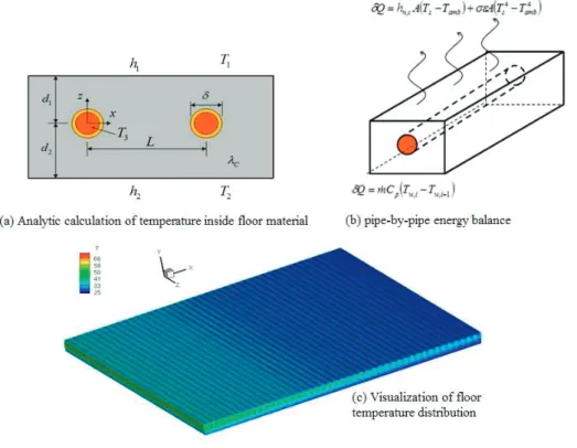
Figure 7: Temperature distribution of floor based on analytic solution and pipe-by-pipe heat balance
3.3 Floor heating simulation
In order to accurately simulate floor heating, we propose a new ‘pipe-by-pipe’ method. As shown in Figure 7 (b), heat transferred to the room by a pipe is equivalent to heat loss by the temperature decrease across pipe:
(
si amb)
(
si amb)
pw(
i i)
c n i h AT T AT T mC T T Q = − + 4 − 4 =− , +1− , , , σε δ , (8)where Ts,i and Ts,i+1 denote averaged surface temperatures of the floor segment with area A under consideration and
its neighbor, respectively, and Ti and Ti+1 are corresponding water temperatures flowing inside the pipe. Here, σ is the Stefan-Boltzmann constant, ε=0.8 is the emissivity of radiation. By successively applying equation (8) to each floor segment, one can determine the entire surface temperature distribution, total heat transferred to the room, and return water temperature. hn,c=kNuL/L is the natural heat transfer coefficient determined by (Churchill and Chu
1975) 2 27 / 8 16 / 9 6 / 1 ] Pr) / 492 . 0 ( 1 [ 387 . 0 825 . 0 ¿ ¾ ½ ¯ ® + + = L L Ra Nu , (9)
where RaL is the Rayleigh number, and L=A/℘ is the characteristic length, and ℘ is the perimeter of the area segment. In order to solve equation (8), we need correlation between the floor surface temperature and the water temperature inside pipe. To this end, we use the analytic solution of the following heat equation
(
)
(
)
, , ) , ( , 2 2 3 2 2 1 1 2 δ λ ≤ + = − − − − = ∇ z x if T z x T T T A h T T A h T C (10)where h1 and h2 are convective heat transfer coefficient for upper and lower sides of floor material (Figure 7(a)), T1,
2
T and T3 are room temperature, bottom wall temperature, and water temperature inside the pipe. δ is the diameter of the pipe and λC is the thermal conductivity of floor material such as cement mortar. The analytic solution of equation (10) takes the following form (Holopainen et al., 2007):
(
)
(
)
(
)
(
) (
)
{
}
»» ¼ º « « ¬ ª ¸ ¹ · ¨ © § + + − − ¸¸ ¹ · ¨¨ © § + + − + − × ¸¸ ¹ · ¨¨ © § − + − − Γ − − + − + + =¦
∞ =1 2 1 2 1 2 1 2 1 1 2 2 1 2 1 3 2 1 2 1 1 1 1 2 cos / 2 exp ) ( ) ( / 2 exp 1 2 / 1 / 1 / ) ( / 1 ) , ( s C C L x s Lz s s g s g z L s s z U U z U U U U L T T U U U T T T T U U z d h T z x T π π π λ π λ (11) where(
)
(
)
(
)
(
)
. 2 2 2 2 4 exp 4 exp 4 exp 2 2 ) ( 2 , 1 1 , ) ( ) ( 2 ln 2 2 1 1 2 1 2 1 3 1 1 1 2 1 2 1 » » ¼ º « « ¬ ª ¸¸ ¹ · ¨¨ © § − ¸¸ ¹ · ¨¨ © § + » » ¼ º « « ¬ ª ¸¸ ¹ · ¨¨ © § − ¸¸ ¹ · ¨¨ © § + − » ¼ º « ¬ ª + ¸ ¹ · ¨ © § − » ¼ º « ¬ ª + ¸ ¹ · ¨ © § − − » ¼ º « ¬ ª ¸ ¹ · ¨ © § − » » ¼ º « « ¬ ª ¸¸ ¹ · ¨¨ © § − ¸¸ ¹ · ¨¨ © § + = = » ¼ º « ¬ ª + = » ¼ º « ¬ ª + + + + ¸ ¹ · ¨ © § = Γ − − − ∞ =¦
s L h s L h s L h s L h d d L s d d L s d L s s L h s L h s g i d h U s s g s g U U L L C C C C i C i C i i C i i i s C π λ π λ π λ π λ π π π π λ π λ λ πλ πδ (12)Here, d1, d2 and L are geometrical parameters defined in Figure 7(a). In this study, these parameters are given as follows:d1=5cm,d2=25cm,L=20cm, and λC =0.4W/m⋅K. The bottom wall temperature is assumed to be 18
oC,
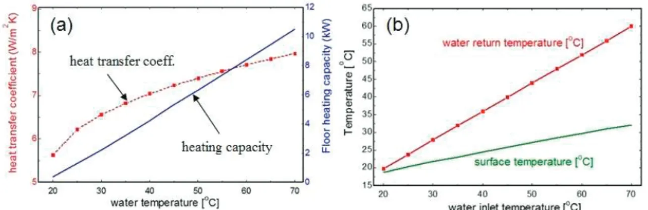
and heat transfer coefficients are iteratively determined until they match computed value by equations (8) and (9). Figure 8 shows results from floor heating simulation, or overall heat transfer coefficient, floor heating capacity, water return temperature, and averaged surface temperature as functions of inlet water temperature. Here, 18oC of
indoor temperature and 10 LPM (liter per minute) of water mass flow rate is assumed. As shown in the figure, overall heat transfer coefficients are in the range of 6 ~ 8 W/m2K, which are in good agreement with previous results
(Karadag 2009). The amount of heat ejected from 100m2 surface, as shown in figure 8, is less than 10 kW for water
temperature up to 70oC. This fact gives a valuable insight into heat pump operation that current heat pumps whose
nominal capacity are 16kW would run under partial load condition, and that there is sufficient room for simultaneous operation for DHW.
Figure 8: floor heating simulation results: (a) heat transfer coefficients & floor heating capacity; (b) Return water temperature and averaged surface temperature at various water inlet temperatures for a 100m2 house.
temperature does not have to exceed 50oC to cover the maximum thermal load. This implies that for low energy
house, high water temperature is no longer required, and this fact is especially favorable to heat pumps with R410A whose maximum condensing temperature is lower than 55oC.
3.4 Discharge water temperature control
The main objective of heating and cooling is to maintain desired indoor temperature with minimal deviation or fluctuation. To this end, heat pumps with fixed rotation frequency usually turn on and off compressors frequently. Whereas heat pumps adopting inverter accomplish this objective by changing the rotation frequency of the compressor according to given load. From equation (1), it is obvious that desired heat pump capacity is
), ( amb
ideal h A T T
Q = id house − (13)
with which indoor temperature remains unchanged once it reaches setting value. However, imposing Qideal as target
is impractical since the exact value of loss coefficient h is hard to know and is changing according to external weather condition. In practice, so called ‘weather compensated control’ is often adopted to achieve energy saving, which changes target discharge temperature to be prescribed on corresponding to outdoor temperature. However, there is no guarantee that prescribed target temperature is right one to match thermal load.
Here, we propose a dynamic discharge water temperature control method purely based on thermo off time, or time required to raise indoor temperature up to thermostat setting temperature. The main idea is to raise (reduce) discharge temperature when measured thermo-off time is too long (short) as compared to desired thermo-off time. This method appears sound in the sense that ill-designed air conditioning devices with excessive capacity result in frequent thermo-off, and vice versa. The logical expression for this control is summarized as follows:
° ¯ ° ® = → − − = → < + = → > − − + − , 52 , , , , min , , max , C T T until off thermo no if dT T T T T if dT T T T T if o new set fail set new set rget a t off thermo set new set rget a t off thermo (14)
where Ttarget,min and Ttarget,max are, respectively, minimal and maximum allowable target thermo-off times. The last
condition is the failsafe condition to prevent no thermo-off due to unexpected decrease of outdoor temperature, which is proven to be necessary. The temperature increment dT+ and dT− are given by
, , min , , min max min , min , max max max , max , max ¸ ¸ ¹ · ¨ ¨ © § − = ¸ ¸ ¹ · ¨ ¨ © § − = − − − + dT T T T dT dT dT T T T dT dT rget ta off thermo rget ta rget ta off thermo rget ta (15)
where a rather arbitrary value 10oC
max =
dT is set as the limitation of the increment to ensure mild variation of temperature. The main advantage of the current control is that it is completely black box approach, which does not need any other information than thermo-off time. Thus, it is applicable to any heating and cooling system
compatible with discharge air/water temperature variation. The impact of the proposed control method on the energy efficiency will be investigated in the following section.
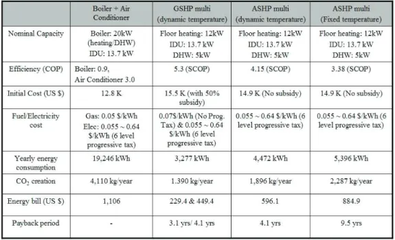
Table 3: Summary of annual simulations
4. SIMULATION RESULTS AND PAYBACK PERIOD ESTIMATION
Summary of simulation described in the previous section is given in Table 3, where annual energy consumption, overall COP, electricity cost and CO2 emission are compared for various solutions.
4.1 Boiler + air conditioner combination
For the simulation of boiler + air conditioner combination (denoted as “conventional system” hereinafter), developed code for heat pump are modified to have COP of 0.9 for water heating at all water temperature up to 70oC,
and reduce the size of sanitary tank to be 20 liter so that it can be included inside the boiler just as current condensing boilers. Computed energy consumption by boiler + air conditioner and annual energy cost agree well with averaged residential energy heating/cooling consumption (~20,000 kWh/year) and corresponding annual heating plus cooling cost (~1,000$) for 100m2 house in Korea. This enhances the reliability of present numerical
simulation.
4.2 Ground source heat pump
As indicated in Table 3, 50% subsidy for the installation cost is considered for GSHP, while no subsidy is assumed for ASHP. For electricity cost, basically current 6-level progressive tariff by KEPCO (Korea Electric Power
Corporation; Lee and Ahn 2006) is considered. In addition to this, fixed rate cost (0.07 $/kWh) is also considered for GSHP since it is highly probable to get progressive tax exemption in the near future for the case of GSHP.
It is shown that overall COP is as high as 5.3 for GSHP, which is defined as annual energy output over energy consumption. Thus, annual energy consumption by GSHP is only 17% of that by the conventional system, resulting in 60% and 80% reduction in annual energy cost with and without progressive tax in electricity. Under this condition, payback periods of GSHP, when it replaces conventional system, are only 3.1 and 4.1 years, respectively. This implies that GSHP is still highly competitive without progressive tax exemption. As shown in Figure 9(b),
especially low running cost is required in winter since, unlike ASHP, the evaporating temperature is less sensitive to outdoor temperature. Thus, monthly energy bill does not exceed 70 $ even with current electricity tariff system. As will be shown, such significant reduction of the running cost is primarily due to dynamic water temperature control.
Figure 9: Results from annual simulation. (a) Instantaneous temperature evolution on January 4 from ASHP and GSHP, (b) monthly energy bill with various solutions
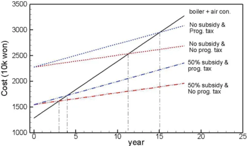
Figure 10: Payback period estimation of GSHP multi (w/ and w/o progressive tax and subsidy) with respect to boiler + air conditioner.
Finally, in order to see the effect of subsidy level, we computed payback again with no subsidy et al. to get 15.1 years and 11.3 year with and without progressive tariff (Figure 10). Therefore, it can be concluded that the level of subsidy is the most important factor to determine viability of GSHP.
4.3 Air source heat pump
Since no subsidy or incentives can be expected for ASHP as mentioned earlier, in order for ASHP to be competitive, its running cost should be substantially less than that of the conventional system. So far, it has not been the case in Korea mainly due to progressive electricity tariff unfavorable to heat pumps. In order to reproduce this situation, we performed ASHP simulation with fixed discharge water temperature for heating at 52oC, and results are summarized
in Table 3. As shown, a reasonable overall COP of 3.38 is obtained and thus, annual energy consumption is only 28% of the conventional system. Nevertheless, annual running cost of ASHP is over 80% of that of the conventional system to end up with almost 10 years of payback. Therefore, ASHP is in the ‘marginal zone’ in the sense that a slight degradation of COP would mean no payback at all.
A nice way of getting out of this zone is to introduce dynamic temperature control, as summarized in Table 3. By adopting dynamic water temperature control, overall COP is increased to be 4.15. Under this condition, the annual energy consumption and energy cost, respectively, are 23% and 54% of the conventional system. Now, corresponding payback period is 4.1 years. As shown in Figure 9(b), monthly running cost of ASHP is at least 20% cheaper than the conventional system for all months. It is surprising to see a simple change in the water temperature control logic can significant enhancement of ASHP feasibility.
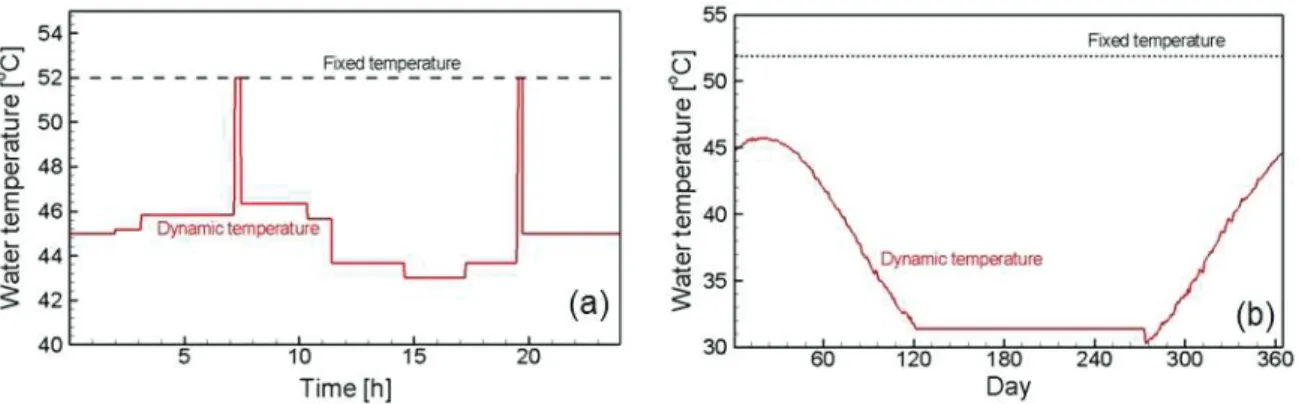
Figure 11: Variation in the floor heating water temperature with A(G)SHP during (a) a day (Jan. 4) and (b) year. For (b), daily average is plotted.
4.4 The effect of dynamic discharge water temperature control
Figure 9(a) shows instantaneous temperature evolutions from both GSHP and ASHP on January, 4 with dynamic water temperature control. It is shown that both indoor and sanitary tank maintain setting temperature with small variation. For floor heating, it is seen that total 30 thermo-off events occurred during a day, which corresponds to 48 minute average thermo-off time. This means that the current dynamic control with 45 minute target thermo-off time (see table 2) is successfully working. Here Ttarget,min and Ttarget,max are set 30 and 60 minutes, respectively.
The corresponding instantaneous water temperature variation is shown in Figure 11(a). Unlike fixed temperature control at 52oC, dynamic scheme changes water temperature from 44oC to 52oC. It is also shown that the
temperature variation roughly corresponds to that of outdoor temperature shown in Figure 9(a). Intended or not, thermo-off time based control method is also a nice weather compensated control without sensing outdoor temperature. This feature is clearly shown by daily mean water discharge temperatures for a year as shown in Figure 11(b). One can see that daily mean water discharge temperature varies from 30oC to 46oC, and is a perfect
compensation to the outdoor temperature shown in Figure 5(a). Therefore, it is no wonder that dynamic control method enhances COP by more than 20% as compared to fixed water temperature method if we recall that COP is highly sensitive to discharge water temperature as shown in Figure 4(b).
6. CONCLUSIONS
In this study, we proposed methodology for computing yearly running cost of air- and ground-source multi heat pumps and performed annual simulations to estimate economical competitiveness of heat pumps in Korea. Considered ones are multi heat pumps for space cooling, floor heating, and domestic hot water, which are considered as the replacement of the gas-fired boiler and air-conditioner combination, or the conventional heating/cooling system in Korea.
Toward accurate running cost simulation, we developed an in-house simulation code that integrates heat pump performance, realistic floor heating, space cooling by indoor units, and hot water storage tank. Annual running cost was computed by integrating input power consumption by the compressor and pumps based on detailed hourly outdoor temperature data of Seoul and domestic hot water usage pattern. For floor heating simulation, we proposed a pipe-by-pipe method combined with analytic solution of heat equation in order to find the relationship between water temperature and mass flow rate inside pipe and heat released by floor surface of given area. We also proposed dynamic discharge water temperature control algorithm for floor heating based purely on target thermostat-off time. It is shown that the annual running costs of ground- and air-source heat pumps are, respectively, 20~45%, and 56% of that of boiler and air conditioner, and that the payback periods are from 3.0 to 15 years depending on the
is small under current electricity tariff. However, when a dynamic water discharge temperature control method is employed, over 20% increase of COP is expected and the corresponding payback period is shortened to be 4.1 years, which is highly appealing to end users who are to be new house residents.
Promising as it may seem, the present study is purely numerical one based on heat pump performance from laboratory data. The confirmation of the present conclusion by field tests at reference sites is the topic of our subsequent research.
REFERENCES
Churchill, S. W., and Chu, H. H. S., 1975, Correlating equations for laminar and turbulent free convection from a vertical plate, Int. J. Heat Mass Transfer, vol. 18: pp. 1323 - 1332.
Holopainen, R., Tuomaala, P., Piippo, J., 2007, Uneven gridding of thermal nodal networks in floor heating simulations, Energy and Buildings, vol. 39: p 1107 – 1114.
Karadag, R., 2009, The investigation of relation between radiative and convective heat transfer coefficients at the ceiling in a cooled ceiling room, Energy conversion and management, vol. 50: p 1-5.
Kasuda, T., and Archenbach, P.R., 1965, Earth Temperature and Thermal Diffusivity at Selected Stations in the United States, ASHRAE Transactions, vol. 71, Part 1.
Kim, S. and Kim, Y., 2003, Development of Standard weather data correlation of Seoul, Journal of Air-conditioning
and Refrigeration, vol. 9, no. 4: p 199-208.
Lee, B. and Ahn, H., 2006, Electricity industry restructuring revisited: the case of Korea, Energy Policy, vol. 34: p 1115-1126.
Liu J., Zhang X., Gao J., and Yang J., 2009, Evaluation of heat exchange rate of GHE in geothermal heat pump systems, Renewable Energy, vol. 34: p 2898 - 2904.
Nelsol, J. E. B., Balakrishnan, A. R., Srinivasa Murthy, S., 1998, Transient analysis of energy storage in a thermally stratified water tank, Int. J Ener. Res., vol. 22: p 867 – 883.
Yokoyama, R., Wakui, T., Kamakari, J., Takemura, K., 2010, Performance analysis of a CO2 heat pump water heating system under a daily change in a standardized demand, Energy, vol. 35: pp. 718-728.
Zhao, P.C., Ding, G. L., Zhang, C. L., Zhao, L., 2003, Simulation of a geothermal heat pump with non-azeotropic mixture, Applied Thermal Engineering 23: p 1515–1524.