NOC-Out: Microarchitecting a Scale-Out Processor
Pejman Lotfi-Kamran
Boris Grot
Babak Falsafi
EcoCloud, EPFL
{pejman.lotfikamran,boris.grot,babak.falsafi}@epfl.ch
Abstract
Scale-out server workloads benefit from many-core proces-sor organizations that enable high throughput thanks to abun-dant request-level parallelism. A key characteristic of these workloads is the large instruction footprint that exceeds the capacity of private caches. While a shared last-level cache (LLC) can capture the instruction working set, it necessitates a low-latency interconnect fabric to minimize the core stall time on instruction fetches serviced by the LLC. Many-core processors with a mesh interconnect sacrifice performance on scale-out workloads due to NOC-induced delays. Low-diameter topologies can overcome the performance limita-tions of meshes through rich inter-node connectivity, but at a high area expense.
To address the drawbacks of existing designs, this work in-troduces NOC-Out – a many-core processor organization that affords low LLC access delays at a small area cost. NOC-Out is tuned to accommodate thebilateralcore-to-cache ac-cess pattern, characterized by minimal coherence activity and lack of inter-core communication, that is dominant in scale-out workloads. Optimizing for the bilateral access pattern, NOC-Out segregates cores and LLC banks into distinct net-work regions and reduces costly netnet-work connectivity by elim-inating the majority of inter-core links. NOC-Out further sim-plifies the interconnect through the use of low-complexity tree-based topologies. A detailed evaluation targeting a 64-core CMP and a set of scale-out workloads reveals that NOC-Out improves system performance by 17% and reduces network area by 28% over a tiled mesh-based design. Compared to a design with a richly-connected flattened butterfly topology, NOC-Out reduces network area by 9x while matching the per-formance.
1. Introduction
Today’s information-centric world is powered by servers. A recent report estimates the server hardware market to exceed $57 billion in 2014 [5], with various online services pro-pelling the growth. The size of the market has motivated both established and start-up hardware makers to develop special-ized processors for server workloads, as evidenced by designs such as Oracle’s T-series and IBM’s POWER.
Recent research examining scale-out workloads behind many of today’s online services has shown that, as a class, these workloads have a set of common characteristics that differentiate them from desktop, media processing, and sci-entific domains [4]. A typical scale-out workload, be it a
streaming service or web search, handles a stream of mostly independent client requests that require accessing pieces of data from a vast dataset. Processing a diversity of requests, scale-out workloads have large active instruction footprints, typically in the order of several megabytes.
The presence of common traits – namely, (a) request inde-pendence, (b) large instruction footprints, and (c) vast dataset sizes – indicates that processors can readily be specialized for this workload class. The abundant request-level parallelism argues for processor designs with a large number of cores to maximize throughput. The independent nature of requests vir-tually eliminates inter-thread communication activity; how-ever, large instruction footprints require a fast communica-tion path between the individual cores and the last-level cache (LLC) containing the applications’ instructions. Finally, the vast dataset dwarfs on-die storage capacities and offers few opportunities for caching due to limited reuse [4].
Taking advantage of common workload features, and driven by the need to increase server efficiency, the indus-try has introduced processors, which we broadly refer to as scale-out processors, that are specialized to scale-out work-loads. An example of an existing scale-out processor design is the Oracle T-series, which features up to 16 cores, 3-6 MB LLC capacities, and a low-latency crossbar interconnect. Ex-tending and formalizing the space of scale-out processors, re-searchers introduced the Scale-Out Processor (SOP) design methodology [15]. The SOP methodology, which provides an optimization framework for deriving optimal core counts and LLC capacities based on microarchitectural and technol-ogy parameters, advocates many cores, modestly-sized LLCs, and low interconnect delays.
With both industry and researchers calling for many-core scale-out processor designs, an open question is how should the cores and LLC be arranged and interconnected for maxi-mum efficiency. In light of known scalability limitations for crossbar-based designs, existing many-core chip multiproces-sors (CMPs), such as Tilera’s Tile series [19], have featured a mesh-based interconnect fabric and a tiled organization. Each tile integrates a core, a slice of the shared LLC with directory, and a router. The resulting organization enables cost-effective scalability to high core counts; however, the mesh-based de-sign sacrifices performance on scale-out workloads due to its large average hop count [15]. Each hop involves a router traversal, which adds delay that prolongs the core stall time on instruction fetches serviced by the LLC.
low-diameter NOC topologies, such as the flattened butterfly [13], that leverage the abundant on-chip wire budget to achieve rich inter-node connectivity. By minimizing the number of router traversals, a low-diameter network improves perfor-mance over a mesh-based design by accelerating accesses to the LLC. However, the performance gain comes at consid-erable area overhead stemming from the use of many-ported routers and a multitude of repeater-intensive long-range links.
In this work, we address the scalability challenge for scale-out processors through NOC-Out – a core, cache, and inter-connect organization specialized for the target workload do-main. We identify the direct communication between cores and LLC banks, which we termbilateral, as the dominant per-mutation in scale-out workloads and show that other forms of communication, including coherence activity, is rare. Based on this insight, NOC-Out decouples LLC tiles from the cores and localizes them in a central portion of the die. The segre-gated organization naturally accommodates the bilateral core-to-cache access pattern. More importantly, with the traffic flowing between spatially distinct regions (cores to caches and back to the cores), NOC-Out virtually eliminates the need for direct inter-core connectivity, affording a significant re-duction in network cost.
To further optimize interconnect cost and performance, NOC-Out deploys simplereduction trees to carry messages from the cores to the centrally-located LLC banks. Each re-duction tree is shared by a small number of cores. A node in a tree is just a buffered 2-input mux that merges packets from a local port with those already in the network. This sim-ple design reduces cost and delay by eliminating the need for routing, multi-port arbitration, complex switches, and deep buffers. Similarly, NOC-Out uses low-complexitydispersion treesto carry the data from the cache banks to the cores. A node in a dispersion tree is a logical opposite of that in a re-duction tree, allowing packets to either exit the network or advancing them up the tree at minimal cost and delay.
We use a full-system simulation infrastructure, along with detailed area and energy models for a 32nm technology node, to evaluate NOC-Out in the context of a 64-core CMP on a set of scale-out workloads. Our results show that NOC-Out matches the performance of a conventional tiled organization with a flattened butterfly interconnect while reducing the net-work area by a factor of 9, from a prohibitive 23mm2to an
affordable 2.5mm2. Compared to a mesh-based design,
NOC-Out improves system performance by 17% while requiring 28% less network area.
2. Background
In this section, we examine scale-out workloads and the de-mands they place on processor designs.
2.1. Scale-Out Workloads
Research analyzing the scale-out workload domain has shown that a key set of traits holds across a wide range
0.0 0.2 0.4 0.6 0.8 1.0 1.2 1 2 4 8 16 32 64 P e r -C o re P e r fo r m a n c e N o r m a li z e d t o 1 c o re # of cores Data Serving (Ideal) Data Serving (Mesh) MapReduce-W (Ideal) MapReduce-W (Mesh)
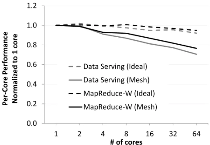
Figure 1: Effect of distance (which grows with core count) on per-core performance for ideal and mesh-based in-terconnects on two scale-out workloads.
of workloads, including web search, media streaming, and web serving. These traits can be summarized as (a) request independence, (b) large instruction footprint, and (c) vast dataset [4]. We next examine each of these traits to under-stand their effect on processor design.
Request Independence: Scale-out workloads handle a
stream of requests that are, to an overwhelming extent, mu-tually independent. Fundamentally, request independence is the feature that makes scale-out workloads inherently parallel and attractive for execution on many-core chips. Another im-plication of request independence is the lack of inter-thread communication. Write sharing among cores working on sep-arate requests is rare due to the vast data working set size; nonetheless, the shared memory programming model is val-ued in the scale-out domain as it simplifies software develop-ment and facilitates the use of existing software stacks.
Large instruction footprint: Active instruction
work-ing sets in scale-out workloads are typically measured in megabytes and are characterized by complex control flow. As a result, private last-level caches tend to lack the requi-site capacity for capturing the instruction footprint. Shared last-level caches, on the other hand, have the capacity and re-duce replication when compared to private caches as different cores are often executing the same workload and can share in-structions [8].
One challenge with large, LLC-resident instruction work-ing sets is that the on-die distance between the cores and the LLC adds delay to the cache access time. Because L1-I misses stall the processor, scale-out workloads are partic-ularly sensitive to the on-die communication delays due to frequent instruction fetches from the LLC.
Figure 1 shows the effect of distance on per-core perfor-mance for two representative scale-out workloads. In this experiment, an 8MB LLC is shared by all cores on the die. The number of cores is indicated on the x-axis; more cores re-sult in a larger die size and a longer average distance between each core and the target LLC bank. The figure compares the
(a) Mesh-based CMP with 64 tiles. !
""#!$%&'(!)*+!
#,-(!
.&-('/,-0
!!$%&'(!
1,2/(-!
(b) Tile organization. !"#$ %$ &$ '$ ($ )$(*+,-.$
/01234$ "0561,7203$ $ !"$8990-7,0:$ (c) Mesh router.Figure 2: Elements of tiled CMPs. performance of an idealized interconnect (labeled "Ideal") in
which only the wire delay is exposed (i.e., routing, arbitra-tion, switching, and buffering all take zero time) to a realistic mesh-based interconnect with a 3-cycle per-hop delay (router and wire delay). To focus the study, we do not model con-tention in either network. As the figure shows, interconnect delay has a significant effect on performance that increases with core count. At 64 cores, the average difference in per-formance between an ideal and mesh-based interconnect is 22%.
Vast dataset: Scale-out workloads operate on vast
amounts of data that is frequently kept in DRAM to reduce the access latency. The data working set of these workloads dwarfs the capacity of on-die caches. Moreover, there is es-sentially no temporal reuse in the data stream. The combi-nation of these features renders on-die caches ineffective for capturing the data working set, indicating that committing large swaths of the die real-estate to cache is not useful. To recap, scale-out workloads are best served by many-core chips featuring a modestly-sized LLC for capturing the in-struction working set and an on-die interconnect optimized for low cache access latency.
2.2. Scale-Out Processors
The observations captured in the previous section are re-flected in several contemporary processors targeted at the scale-out market. A representative example is the Oracle T-series (formerly, Sun Niagara) family of processors. De-pending on the model, the T-series features up to 16 cores, a banked LLC with 3-6 MB of storage capacity, and a delay-optimized crossbar switch connecting the cores to the cache banks.
Extending and formalizing the space of existing scale-out processor designs, researchers have proposed the SOP methodology – a framework for performing cost-benefit anal-ysis at the chip level in the context of scale-out work-loads [15]. Given a set of microarchitectural and technol-ogy parameters, the SOP methodoltechnol-ogy uses the metric of per-formance density to derive optimal resource configurations,
Figure 3: Flattened butterfly topology (links from only one node shown for clarity).
such as the number of cores and LLC capacity. An impor-tant conclusion of the work is that, indeed, scale-out proces-sors benefit from many cores with a modestly-sized LLC and a fast interconnect. Subsequent work has demonstrated that many-core processor configurations derived using the SOP methodology improve performance and TCO at the datacen-ter level [6]. However, a key limitation of these earlier efforts has been their reliance on crossbar interconnects whose poor scalability forced suboptimal design choices.
2.3. Existing Many-Core Organizations
To overcome the scalability limitations of crossbar-based de-signs, emerging many-core processors, such as Tilera’s Tile series, employ a tiled organization with a fully distributed last-level cache. Figure 2(a) shows an overview of a generic CMP based on a tiled design. Each tile, pictured in Figure 2(b), consists of a core, a slice of the distributed last-level cache, a directory slice, and a router. The tiles are linked via a routed, packet-based, multi-hop interconnect in a mesh topology.
The tiled organization and a structured interconnect fabric allow mesh-based designs to scale to large core counts. Un-fortunately, the regularity of the mesh topology works to its disadvantage when it comes to performance scalability. Each hop in a mesh network involves the traversal of a multi-ported
0 1 2 3 4 5
Data Serving MapReduce-C MapReduce-W SAT Solver Web Frontend Web Search Mean
% o f LL C A cc e ss e s T ri g g e ri n g a S n o o p A cc e ss
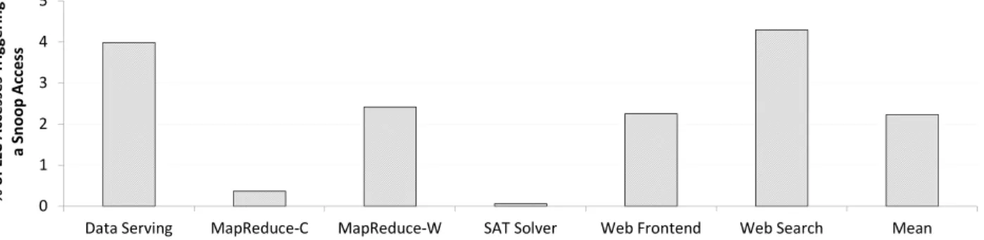
Figure 4: Percentage of LLC accesses causing a snoop message to be sent to a core.
router, shown in Figure 2(c), which adds delay due to the need to access the packet buffers, arbitrate for resources, and navi-gate the switch. As Figure 1 shows, in a 64-core CMP, these delays diminish the performance of a mesh-based tiled CMP by 22% compared to an ideal fabric in which only the wire delay is exposed.
To overcome the performance drawbacks of mesh-based in-terconnects, researchers developed low-diameter topologies suitable for on-die implementation. These topologies use rich inter-node connectivity to bypass intermediate routers between a packet’s source and destination nodes. A state-of-the-art low-diameter topology is the flattened butterfly [13], shown in Figure 3. The flattened butterfly uses a set of dedi-cated channels to fully connect a given node to others along the row and column. The resulting network requires, at most, two hops (one in each of the X and Y dimensions) to deliver the packet to the destination. In doing so, the flattened but-terfly greatly reduces the contribution of routers to the end-to-end delay, allowing performance to approach that of an ideal interconnect.
Problematically, the performance advantages of the flat-tened butterfly, or another richly-connected NOC, come at considerable area expense stemming from the use of many-ported routers and a multitude of links. For instance, in the flattened butterfly in Figure 3, each router necessitates 14 net-work ports (7 in each of the two dimensions) plus a local port. The network ports are costly due to the presence of deep packet buffers necessary to cover the flight time of the long-range links. Meanwhile, the routers’ internal switch fabric is area-intensive due the need to interconnect a large number of ports. Finally, links consume valuable on-die real-estate due to the need for frequent repeater placement1, even though wires themselves can be routed over tiles.
To summarize, existing NOC architectures require an uneasy choice between performance and area-efficiency. Meanwhile, scale-out processors demand both – good performance and good area-efficiency.
1Repeaters are necessary to overcome poor RC characteristics of wires in
current and future technologies.
3. Memory Traffic in Scale-Out Workloads
In order to maximize the efficiency of scale-out processors, we examine the memory traffic in scale-out workloads to iden-tify opportunities for specialization.
As noted earlier, scale-out workloads have large instruction footprints and vast datasets. Cores executing these workloads frequently access the LLC because neither the instructions nor the datasets fit in L1 caches. The multi-megabyte instruc-tion footprints of scale-out workloads can be readily accom-modated in the LLC while the vast datasets dwarf the LLC capacity and reside in memory. Consequently, the majority of accesses to the instruction blocks hit in the LLC while many dataset accesses miss and are filled from main memory.
On an L1 miss, the directory controller and the LLC check if the block is available on chip. If so, and if LLC’s copy is the most recent, the LLC will service the miss and send the data to the requesting core. If the requesting core signals that it needs to modify the block, the directory will also sendsnoop messages to the set of sharers, instructing them to invalidate their copy. Conversely, if the directory indicates that another core has the block, it will send a snoop message to the appro-priate core, instructing it to forward the block to the requester. Finally, in the case of a miss, the LLC fetches the block from main memory and returns it to the requesting core.
Importantly, coherence activity and core-to-core communi-cation (i.e., L1-to-L1 forwarding) is triggered only as a result of data sharing at the L1 level. However, due to the high-level behavior of scale-out workloads, this type of data sharing is rare. Instructions are actively shared, but are read-only and served from the LLC; dataset is vast, and the likelihood of two independent requests sharing a piece of data is low.
Figure 4 shows the fraction of accesses to the LLC that cause a snoop message to be sent to an L1 cache across six scale-out workloads. As expected, coherence activity is neg-ligible in these workloads, with an average of two out of 100 LLC accesses triggering a snoop. Earlier work made similar observations for both scale-out [4] and server [14] workloads. The lack of coherence activity in scale-out workloads im-plies that the dominant traffic flow is from the cores to the LLC and back to the cores. We refer to this phenomenon as core-to-cachebilateralaccess pattern. In tiled processors, the coupled nature of core and LLC slices means that accesses
$ C C C C C C C C C C C C C C C C C C C C C C C C C C C C C C C C C C C C C C C C C C C C C C C C C C C C C C C C C C C C C C C C M e m o ry C h an n e l 4 M e m o ry C h an n e l 3 M e m o ry C h an n e l 2 M e m o ry C h an n e l 1 Flattened Butterfly
Figure 5: NOC-Out organization.
to the last-level cache from each individual core, over time, target all of the tiles, resulting in an all-to-all traffic pattern at the chip level. Achieving low latency under all-to-all traffic requires a richly connected topology, necessarily resulting in high area and wire cost.
4. NOC-Out
NOC-Out is a processor organization optimized for the bilat-eral access pattern dominant in scale-out workloads. NOC-Out leverages two insights to minimize interconnect delays at a small area footprint. First, NOC-Out segregates the LLC slices from the cores into separate cache-only tiles and con-centrates the cache tiles in the center of the die. The segrega-tion of cores and the LLC breaks the all-to-all traffic pattern characteristic of tiled CMPs and establishes a bilateral traf-fic flow between core and cache regions. Second, NOC-Out takes advantage of the bilateral traffic to limit network con-nectivity, enabling a reduction in network cost. Specifically, NOC-Out eliminates the bulk of the core-to-core links and the supporting router structures, preserving a minimum degree of connectivity to enable each core to reach the LLC region.
Figure 5 shows a high-level view of the proposed organiza-tion, featuring LLC slices in the center of the die and core tiles on both sides of the LLC. NOC-Out uses simple, routing-free reduction treesto guide packets toward the centralized cache banks, anddispersion trees, which are logical opposites of re-duction trees, to propagate response data and snoop traffic out to the cores. Every reduction and dispersion tree connects a small number of cores to exactly one cache bank. The LLC banks are linked in a flattened butterfly topology forming a low-latency NUCA cache. Notably, NOC-Out does not sup-port direct core-to-core connectivity, requiring all traffic to flow through the LLC region.
In the rest of the section, we detail the organization of the reduction, dispersion, and LLC networks.
4.1. Reduction Network
The reduction network is designed for a low-latency delivery of packets from the cores to the centralized cache banks. Fig-ure 6(a) shows key featFig-ures of a reduction tree, which spans
!"#$%& '()*"+,& -& .& .& .& .&
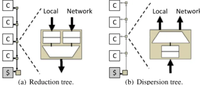
(a) Reduction tree.
!"#$%& '()*"+,& -& .& .& .& .& (b) Dispersion tree.
Figure 6: Details of NOC-Out networks.
a column of cores and terminates at the LLC bank at the end of the column. Effectively, a reduction tree is a many-to-one interconnect, with all packets that enter a reduction tree flow-ing to the same destination cache bank. A node in the tree is a buffered, flow-controlled, two-input multiplexer that merges packets from the local port with those already in the network.
Compared to a conventional packet-based NOC, the reduc-tion network does not require routing, as all packets flow to a common destination. The switch, typically implemented as a crossbar or a mux tree in conventional NOCs, is reduced to a simple two-input mux in a reduction tree. The reduction net-work is similar to conventional NOCs in that it benefits from the use of virtual channels for protocol deadlock avoidance, and as such requires a virtual channel allocation mechanism. However, with just two ports (local and network), the VC allo-cator is trivially simple. In fact, given the low memory-level parallelism of scale-out workloads [4], static-priority arbitra-tion policies that always prioritize the network over the local port (or vice-versa) tend to work well and afford further sim-plification of the arbitration logic.
NOC-Out distinguishes three message classes – data re-quests, snoop rere-quests, and responses (both data and snoop) – to guarantee network-level deadlock freedom for its coher-ence protocol. Of these, only data requests and responses travel through the reduction trees, as snoop requests can only originate at the directory nodes at the LLC. As a result, each port in a reduction tree has two virtual channels, one per mes-sage class.
Upon arrival at a router in a reduction tree, a packet is buffered in the appropriate VC (determined by the packet’s message class). With a total of four VCs in a router (two ports with two VCs per port), a 4:1 arbiter selects a winning VC based on priority and downstream buffer availability. In this work, we assume the following fixed priority ordering of VCs (highest to lowest): network responses, local responses, network requests, local requests. By prioritizing the network over the local port, we seek to mitigate the latency disadvan-tage of cores that are more distant from the LLC. Because a reduction tree router has exactly one output port, routing and output port selection logic is unnecessary, and just one arbiter is required per node.
4.2. Dispersion Network
The dispersion network carries packets (data responses and snoop requests) from the LLC to the cores. Figure 6(b) shows
a logical view of a dispersion tree. A dispersion tree is a log-ical opposite of the reduction tree, with a single source (a cache bank) and multiple destinations (cores). Each node in a tree is a buffered, flow-controlled demultiplexer that selects a local output port for packets that have reached their desti-nation or propagates them farther up the tree toward the next node.
As is the case with the reduction network, virtual channels are necessary for deadlock avoidance to guarantee that snoop requests do not block data responses from reaching their des-tination. With two VCs per node (one per message class), on each clock cycle, simple control logic (1) uses message pri-ority and buffer availability to select a winning VC, and (2) sets up demux control to forward a flit from the selected VC to the local or network output. Again, we use a static priority assignment to prioritize reply messages over snoop requests, subject to buffer availability.
4.3. LLC Network
As described above, NOC-Out segregates core and LLC slices2into separate tiles. Because each core connects to just one LLC tile through its reduction and dispersion trees, NOC-Out relies on a richly-connected flattened butterfly network to route traffic between LLC tiles. The choice of the network is motivated by the need to minimize delay and reduce con-tention in the LLC region.
In order to reduce the area and channel expense of the flattened butterfly, NOC-Out takes advantage of the fact that the number of LLC tiles need not match the number of core tiles. The number of LLC tiles can be reduced because low instruction- and memory-level parallelism in scale-out work-loads naturally dampen the bandwidth pressure on the LLC. Our empirical data shows that a design with four cores per one LLC bank achieves a level of performance that is within 2% of a system with an equal number of cores and banks. Moreover, each LLC tile can house multiple banks that share the router. A reduction in the number of the LLC tiles di-minishes the cost and extent of the richly-connected LLC net-work.
4.4. Additional Considerations
Before concluding the description of NOC-Out, we highlight several additional aspects of the proposed design; namely, its flow control architecture, connectivity to off-die interfaces, and support for shared memory.
Flow control: All three NOC-Out networks (reduction,
dispersion, and LLC) rely on conventional virtual channel credit-based flow control. The amount of buffering per port in both reduction and dispersion trees is insignificant (a few flits per VC) thanks to a short round-trip credit time resulting from a trivial pipeline. The flattened butterfly LLC network requires more buffering per port to cover the multi-cycle de-lays of long-range links and multi-stage routers; however, this cost is restricted to just a fraction of the nodes.
2An LLC slice is composed of data, tags, and directory.
Off-die interfaces:Contemporary server chips integrate a
number of off-die interfaces, such as memory controllers, to improve performance and reduce system cost. In the NOC-Out design, these are accessed through dedicated ports in the edge routers of the LLC network, as shown in Figure 5.
Shared memory: Shared memory is a prominent
fea-ture of today’s software stacks. Despite being optimized for the bilateral core-to-cache communication, NOC-Out fully supports the shared memory paradigm through conventional hardware coherence mechanisms, preserving full compati-bility with existing software. What NOC-Out sacrifices by eliminating direct core-to-core connectivity is the support for locality-optimized communication. Instead, NOC-Out spe-cializes for cost and performance on scale-out server work-loads that do not benefit from locality optimizations.
5. Methodology
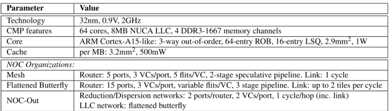
Table 1 summarizes the key elements of our methodology, with the following sections detailing the specifics of the eval-uated designs, technology parameters, workloads, and simu-lation infrastructure.
5.1. CMP Parameters
Our target is a many-core CMP implemented in 32nm tech-nology. We use the Scale-Out Processor methodology [15] to derive the optimal core count, number of memory controllers, and LLC capacity for the assumed technology and microar-chitectural parameters. The resulting processor features 64 cores, 8MB of last-level cache, and four DDR3-1667 memory channels. Core microarchitecture is modeled after an ARM Cortex-A15, a three-way out-of-order design with 32KB L1-I and L1-D caches. Cache line size is 64B.
We consider three system organizations, as follows:
Mesh: Our baseline for the evaluation is a mesh-based
tiled CMP, as shown in Figure 2. The 64 tiles are organized as an 8-by-8 grid, with each tile containing a core, a slice of the LLC and a directory node.
At the network level, a mesh hop consists of a single-cycle link traversal followed by a two-stage router pipeline for a total of three cycles per hop at zero load. The router per-forms routing, VC allocation, and speculative crossbar (XB) allocation in the first cycle, followed by XB traversal in the next cycle. Each router port has 3 VCs to guarantee deadlock freedom across three message classes: data requests, snoop requests, and responses. Each VC is 5 flits deep, which is the minimum necessary to cover the round-trip credit time.
Flattened Butterfly (FBfly): The FBfly-based CMP has
the same tiled organization as the mesh baseline, but enjoys rich connectivity afforded by the flattened butterfly organi-zation as shown in Figure 3. Each FBfly router has 14 net-work ports (7 per dimension) plus a local port. Due to high arbitration complexity, the router does not employ specula-tion, resulting in a three-stage pipeline. Each router port has
Table 1: Evaluation parameters. Parameter Value
Technology 32nm, 0.9V, 2GHz
CMP features 64 cores, 8MB NUCA LLC, 4 DDR3-1667 memory channels
Core ARM Cortex-A15-like: 3-way out-of-order, 64-entry ROB, 16-entry LSQ, 2.9mm2, 1W
Cache per MB: 3.2mm2, 500mW
NOC Organizations:
Mesh Router: 5 ports, 3 VCs/port, 5 flits/VC, 2-stage speculative pipeline. Link: 1 cycle
Flattened Butterfly Router: 15 ports, 3 VCs/port, variable flits/VC, 3 stage pipeline. Link: up to 2 tiles per cycle
NOC-Out Reduction/Dispersion networks: 2 ports/router, 2 VCs/port, 1 cycle/hop (inc. link)
LLC network: flattened butterfly three VCs to guarantee deadlock freedom. The number of flit buffers per VC is optimized based on the location of the router in the network to minimize buffer requirements. Finally, the link delay is proportional to the distance spanned by the link. Given our technology parameters (detailed below) and tile di-mensions, a flit in the channel can cover up to two tiles in a single clock cycle.
NOC-Out: Our proposed design, described in Section 4,
segregates core and LLC tiles, and localizes the LLC in the center of the die. To connect cores to the LLC, NOC-Out uses specialized reduction and dispersion networks. Direct inter-core connectivity is not supported and all traffic must flow through the LLC region.
Both the reduction and dispersion networks require just two VCs per port. In the reduction network, only data re-quests and responses flow from the cores to the cache, as snoop requests cannot originate at the core tiles. Similarly, the response network only needs to segregate snoop requests and data responses, as data requests cannot originate at the LLC. In the absence of contention, both networks have a single-cycle per-hop delay, which includes traversal of both the link and the arbitrated mux (in the reduction tree) or de-mux (in the dispersion tree). This delay is derived based on the technology parameters and tile dimensions.
The LLC is organized as a single row of tiles, with each tile containing 1 MB of cache and a directory slice. The as-pect ratio of the LLC tiles roughly matches that of the core tiles, allowing for a regular layout across the die, as shown in Figure 5. LLC tiles are internally banked to maximize throughput. For the evaluation, we model two banks per tile (16 LLC banks, in total), as our simulations show that this configuration achieves similar throughput at lower area cost as compared to designs with higher degrees of banking. The eight LLC tiles are fully connected via a one-dimensional flat-tened butterfly. LLC routers feature a 3-stage non-speculative pipeline, with three VCs per input port.
5.2. Technology Parameters
We use publicly available tools and data to estimate the area and energy of the various network organizations. Our study targets a 32nm technology node with an on-die voltage of 0.9V and a 2GHz operating frequency.
We use custom wire models, derived from a combination of sources [2, 10], to model links and router switch fabrics. For links, we model semi-global wires with a pitch of 200nm and power-delay-optimized repeaters that yield a link latency of 125ps/mm. On random data, links dissipate 50fJ/bit/mm, with repeaters responsible for 19% of link energy. For area estimates, we assume that link wires are routed over logic or SRAM and do not contribute to network area; however, repeater area is accounted for in the evaluation.
Our buffer models are taken from ORION 2.0 [11]. We model flip-flop based buffers for mesh and NOC-Out, as both have relatively few buffers per port. For the flattened butter-fly, we assume SRAM buffers that are more area- and energy-efficient than flip-flops for large buffer configurations.
Cache area, energy, and delay parameters are derived via CACTI 6.5 [18]. A 1MB slice of the LLC has an area of 3.2mm2 and dissipates on the order of 500mW of power,
mostly due to leakage.
Finally, parameters for the ARM Cortex-A15 core are bor-rowed from Microprocessor Report and scaled down from the 40nm technology node to the 32nm target. Core area, includ-ing L1 caches, is estimated at 2.9mm2. Core power is 1.05W at 2GHz. Core features include 3-way decode/issue/commit, 64-entry ROB, and 16-entry LSQ.
5.3. Workloads
We use scale-out workloads from CloudSuite [3]. The work-loads include Data Serving, MapReduce, Web Frontend, SAT Solver, and Web Search. We consider two MapReduce work-loads – text classification (MapReduce-C) and word count (MapReduce-W). For the Web Frontend workload, we use the e-banking option from SPECweb2009 in place of its open-source counterpart from CloudSuite, as SPECweb2009 ex-hibits better performance scalability at high core counts. Two of the workloads – SAT Solver and MapReduce – are batch, while the rest are latency-sensitive and are tuned to meet the response time objectives. Prior work [4] has shown that these workloads have characteristics representative of the broad class of server workloads as described in Section 2.1.
Four out of six workloads scale to 64 cores. The other two, namely Web Serving and Web Search, only scale to 16 cores
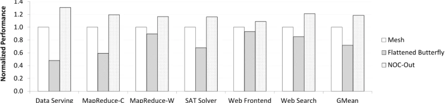
0.0 0.2 0.4 0.6 0.8 1.0 1.2 1.4
Data Serving MapReduce-C MapReduce-W SAT Solver Web Frontend Web Search GMean
N o r m a li z e d P e r fo r m a n c e Mesh Flattened Butterfly NOC-Out
Figure 7: System performance, normalized to a mesh-based design. due to various software bottlenecks. For these two workloads,
we choose the 16 tiles in the center of the die for the mesh and flattened butterfly designs, and the 16 core tiles adjacent to the LLC in the NOC-Out design.
5.4. Simulation Infrastructure
We estimate the performance of the various processor designs using Flexus full-system simulation [22]. Flexus extends the Virtutech Simics functional simulator with timing models of cores, caches, on-chip protocol controllers, and interconnect. Flexus models the SPARC v9 ISA and is able to run unmodi-fied operating systems and applications.
We use the SimFlex multiprocessor sampling methodol-ogy [22]. Our samples are drawn over an interval of 10 seconds of simulated time. For each measurement, we launch simulations from checkpoints with warmed caches and branch predictors, and run 100K cycles (2M cycles for Data Serving) to achieve a steady state of detailed cycle-accurate simulation before collecting measurements for the subsequent 50K cycles. We use the ratio of the number of ap-plication instructions to the total number of cycles (including the cycles spent executing operating system code) to measure performance; this metric has been shown to accurately reflect overall system throughput [22]. Performance measurements are computed with 95% confidence with an average error of less than 4%.
6. Evaluation
We first examine system performance and area efficiency of mesh, flattened butterfly, and NOC-Out designs given a fixed 128-bit link bandwidth. We then present an area-normalized performance comparison, followed by a discussion of power trends.
6.1. System Performance
Figure 7 shows full system performance, normalized to the mesh, under the various NOC organizations. Compared to the mesh, the richly-connected flattened butterfly topology improves performance by 7-31%, with a geomean of 17%. The highest performance gain is registered on the Data Serv-ing workload, which is characterized by very low ILP and MLP, making it particularly sensitive to the LLC access la-tency. 0 5 10 15 20 25
Mesh Flattened Butterfly NOC-Out
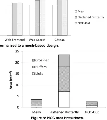
A re a ( m m 2) Crossbar Buffers Links
Figure 8: NOC area breakdown.
On average, the proposed NOC-Out design matches the performance of the flattened butterfly. On Data Serving, bank contention is responsible for a small performance degradation in NOC-Out, resulting in lower performance as compared to the flattened butterfly. On the other hand, on Web Search (a 16-core workload), NOC-Out enjoys a smaller average com-munication distance between the cores and the LLC, resulting in higher performance. The bottom line is that NOC-Out im-proves system performance by 17% over the mesh, and, on average, matches the performance of the flattened butterfly.
We conclude the performance assessment by noting that while the bisection bandwidths of the various topologies are different, the networks are not congested. Differences in la-tency, not bandwidth, across the topologies are responsible for the performance variations.
6.2. NOC Area
Figure 8 breaks down the NOC area of the three organizations by links, buffers, and crossbars. Only repeaters are accounted for in link area, as wires are assumed to be routed over tiles.
At over 23mm2, the flattened butterfly has the highest NOC area, exceeding that of the mesh by nearly a factor of 7. The large footprint of the flattened butterfly is due to its large link budget and the use of buffer-intensive many-ported routers.
NOC-Out’s interconnect footprint of 2.5mm2is the lowest
among the evaluated designs, requiring 28% less area than a mesh and over 9 times less area than a flattened butterfly. NOC-Out’s area advantage stems from minimal connectivity among the majority of the nodes (i.e., cores) and from the
0.0 0.2 0.4 0.6 0.8 1.0 1.2 1.4
Data Serving MapReduce-C MapReduce-W SAT Solver Web Frontend Web Search GMean
N o r m a li z e d P e r fo r m a n c e Mesh Flattened Butterfly NOC-Out
Figure 9: System performance, normalized to a mesh-based design, under a fixed NOC area budget. use of low-complexity network trees (reduction and
disper-sion) that minimize router costs. Each of the two tree net-works contributes just 18% to the total NOC footprint. In con-trast, the flattened butterfly interconnecting NOC-Out’s LLC region constitutes 64% of the total network area while linking just 11% of the tiles.
6.3. Area-Normalized Comparison
The performance and area analysis in the previous two sec-tions assumed a fixed link width of 128 bits, resulting in vastly different NOC area costs and bisection bandwidths. To better understand how the various designs compare given a fixed NOC budget, we assess the performance of the mesh and flat-tened butterfly using NOC-Out’s area of 2.5mm2as a limiting
constraint. We reduce the width of both mesh and flattened butterfly NOCs until each of their respective areas (links + routers) equals that of NOC-Out and then measure the perfor-mance of the resulting designs.
Figure 9 summarizes the results of the study, with perfor-mance of the three organizations normalized to that of the mesh. Given a smaller area budget, the performance of both mesh and flattened butterfly degrades. The degradation is small in the mesh network, as the increase in the serializa-tion latency continues to be dwarfed by the header delay. In contrast, the richly-connected flattened butterfly sees its link bandwidth shrink by a factor of 7, significantly impacting end-to-end latency through a spike in the serialization delay. Com-pared to the flattened butterfly at the same area budget, NOC-Out enjoys a 65% performance advantage. Compared to the mesh, NOC-Out’s performance edge is 19%.
6.4. Power Analysis
Our analysis shows that the NOC is not a significant con-sumer of power at the chip level. For all three organizations, NOC power is below 2W. In contrast, cores alone consume in excess of 60W. Low ILP and MLP of scale-out workloads is the main reason for the low power consumption at the NOC level. Another factor is the near-absence of snoop traffic in these workloads.
NOC-Out results in the most energy-efficient NOC design, dissipating 1.3W of power, on average. Mesh and flattened butterfly average 1.8W and 1.6W, respectively. In all organi-zations, most of the energy is dissipated in the links. NOC-Out’s higher efficiency stems from the lower average distance
between the cores and the LLC, resulting in less energy spent in the wires. Meanwhile, the flattened butterfly’s rich connec-tivity gives it an advantage over the mesh.
6.5. Summary
The evaluation results show that NOC-Out offers the perfor-mance of the richly-connected flattened butterfly topology at a fraction of the network area. Whereas the flattened butter-fly requires a prohibitive 23mm2of die real-estate, NOC-Out necessitates just 2.5mm2 for the interconnect. When
con-strained to NOC-Out’s area budget, the performance of the flattened butterfly diminishes, giving NOC-Out a 65% perfor-mance advantage. In comparison to a mesh, NOC-Out im-proves performance by 17% and reduces the network area footprint by 28%.
7. Discussion
7.1. Scalability of NOC-Out
So far, our description and evaluation of NOC-Out has been in the context of a 64-core CMP. NOC-Out can be readily scaled to support larger numbers of cores through the use of concentration and, in configurations featuring hundreds of cores, through judicious use of express channels in reduction and dispersion networks. If necessary, the LLC network can be scaled up by extending its flattened butterfly interconnect from one to two dimensions. We now briefly discuss each of these options.
Concentration: Concentration can be used to reduce the
network diameter by aggregating multiple terminals (e.g., cores) at each router node [2]. In the case of reduction and dispersion networks, a factor of two concentration at each node (i.e., two adjacent cores sharing a local port of the mux/demux) could be used to support twice the number of cores of the baseline design at nearly the same network area cost. With four times more nodes in the network and a con-centration factor of four, we find that the 16B links in the tree networks are bottlenecked by insufficient bandwidth, necessi-tating either additional or wider links.
Express links: In future CMPs with hundreds of cores,
the height of the reduction and dispersion trees may become a concern from a performance perspective. To mitigate the tree delay, express links can be judiciously inserted into the
tree to bypass some number of intermediate nodes, allowing performance to approach that of an "ideal" wire-only network. While express links increase the cost of the network due to greater channel expense, they are compatible with the simple node architectures described in Sections 4.1 and 4.2 and do not necessitate the use of complex routers.
Flattened butterfly in LLC: When executing scale-out
workloads, much of the useful LLC content is the instruc-tion footprint and OS data. Because this content is highly amenable to sharing by all the cores executing the same bi-nary, adding cores to a scale-out processor does not mandate additional LLC capacity [15]. Should the need arise, how-ever, to expand the LLC beyond a single row of tiles, the flat-tened butterfly network interconnecting the tiles can be read-ily scaled from one to two dimensions. While an expanded flattened butterfly increases the cost of NOC-Out, the expense is confined to the fraction of the die occupied by the LLC. 7.2. Comparison to Prior Work
NOC-Out is not the first attempt to specialize the on-chip in-terconnect to a specific application domain. Bakhoda et al. proposed a NOC design optimized for GPU-based throughput accelerators [1]. Significant similarities and differences exist between the two efforts. Both designs address the needs of thread-rich architectures characterized by a memory-resident data working set and a many-to-few-to-many traffic pattern. But whereas workloads running on throughput accelerators are shown to be insensitive to NOC latency, we show scale-out workloads to be highly sensitivity to interconnect delays due to frequent instruction fetches from the LLC. As a result, NOC-Out innovates in the space of delay-optimized on-chip topologies, whereas prior work has focused on throughput and cost in the context of meshes.
One effort aimed at boosting NOC efficiency specifically in the context of server processors was CCNoC, which proposed a dual-mesh interconnect with better cost-performance char-acteristics than existing multi-network alternatives [20]. Our work shows that mesh-based designs are sub-optimal from a performance perspective in many-core server processors.
A number of earlier studies sought to reduce NOC area cost and complexity through microarchitectural optimizations in crossbars [12, 21], buffers [17], and links [16]. A recent study examined challenges of NOC scalability in kilo-node chips and proposed an interconnect design that co-optimized buffering, topology, and flow control to reduce NOC area and energy [7]. All of these efforts assume a conventional tiled organization. In contrast, our NOC-Out design lowers NOC area overheads by limiting the extent of on-die connectivity. However, NOC-Out’s efficiency can be further improved by leveraging many of the previously proposed optimizations.
Finally, Huh et al. preceded NOC-Out in proposing a seg-regated NUCA CMP architecture in which core and LLC tiles are disjoint [9]. Our design is different from Huh’s in that it seeks to reduce the number of cache tiles to lower network
cost, whereas Huh relied on a sea of cache tiles to optimize data placement and partitioning.
8. Conclusion
Server processors for scale-out workloads require many cores to maximize performance per die by exploiting request-level parallelism abundant in these workloads. Standing in the way of seamless performance scale-up resulting from additional cores is the on-die interconnect that adds delay on instruc-tion fetches serviced by the last-level cache. The performance penalty is particularly acute in mesh-based networks that re-quire a large number of router traversals on a typical LLC access. While a low-diameter flattened butterfly topology overcomes the performance bottleneck of meshes, it incurs a high area overhead through the use of many-ported routers and repeater-intensive long-range links.
This work introduced NOC-Out, a processor organization tuned to the demands of scale-out workloads. NOC-Out seg-regates LLC banks from core tiles and places the cache in the center of the die, naturally accommodating the bilateral core-to-cache data access pattern characteristic of scale-out work-loads. With the bulk of the traffic flowing to the LLC and directly back to the cores, NOC-Out simplifies the intercon-nect by restricting direct conintercon-nectivity among the cores. NOC-Out farther improves network cost and latency characteristics through the use of simple tree topologies that take advantage of the bilateral traffic pattern between the cores and the LLC. Finally, NOC-Out optimizes the intra-LLC interconnect by reducing the number of LLC tiles for a fixed cache capacity with respect to the conventional tiled design. The combina-tion of these optimizacombina-tions enable a low-cost low-latency in-terconnect fabric that matches the performances of a flattened butterfly at the cost of a mesh.
9. Acknowledgments
This work was partially supported by EuroCloud, Project No 247779 of the European Commission 7th RTD Framework Programme – Information and Communication Technologies: Computing Systems.
References
[1] A. Bakhoda, J. Kim, and T. M. Aamodt, “Throughput-Effective On-Chip Networks for Manycore Accelerators,” in International Symposium on Microarchitecture, December 2010, pp. 421–432.
[2] J. D. Balfour and W. J. Dally, “Design Tradeoffs for Tiled
CMP On-Chip Networks,” inInternational Conference on
Su-percomputing, June 2006, pp. 187–198.
[3] “CloudSuite 1.0,” 2012. [Online]. Available: http://parsa.epfl. ch/cloudsuite
[4] M. Ferdman, A. Adileh, O. Kocberber, S. Volos, M. Alisafaee, D. Jevdjic, C. Kaynak, A. D. Popescu, A. Ailamaki, and B. Fal-safi, “Clearing the Clouds: A Study of Emerging Scale-Out
Workloads on Modern Hardware,” inInternational Conference
on Architectural Support for Programming Languages and Op-erating Systems, March 2012, pp. 37–48.
[5] “Global Server Hardware Market 2010-2014,” March 2011. [Online]. Available: http://www.technavio.com/content/ global-server-hardware-market-2010-2014
[6] B. Grot, D. Hardy, P. Lotfi-Kamran, B. Falsafi, C. Nicopou-los, and Y. Sazeides, “Optimizing Data-Center TCO with
Scale-Out Processors,”IEEE Micro, vol. 32, no. 5, pp. 52–63,
September/October 2012.
[7] B. Grot, J. Hestness, S. W. Keckler, and O. Mutlu, “Kilo-NOC: A Heterogeneous Network-on-Chip Architecture for
Scalabil-ity and Service Guarantees,” inInternational Symposium on
Computer Architecture, June 2011, pp. 268–279.
[8] N. Hardavellas, M. Ferdman, B. Falsafi, and A. Ailamaki, “Re-active NUCA: Near-Optimal Block Placement and Replication
in Distributed Caches,” inInternational Symposium on
Com-puter Architecture, June 2009, pp. 184–195.
[9] J. Huh, C. Kim, H. Shafi, L. Zhang, D. Burger, and S. W. Keck-ler, “A NUCA Substrate for Flexible CMP Cache Sharing,” in International Conference on Supercomputing, June 2005, pp. 31–40.
[10] “International Technology Roadmap for Semiconductors (ITRS), 2011 Edition.” [Online]. Available: http://www.itrs. net/Links/2011ITRS/Home2011.htm
[11] A. Kahng, B. Li, L.-S. Peh, and K. Samadi, “ORION 2.0: A Fast and Accurate NoC Power and Area Model for Early-Stage
Design Space Exploration,” inDesign, Automation, and Test in
Europe, April 2009, pp. 423–428.
[12] J. Kim, “Low-Cost Router Microarchitecture for On-Chip
Net-works,” inInternational Symposium on Microarchitecture,
De-cember 2009, pp. 255–266.
[13] J. Kim, J. Balfour, and W. Dally, “Flattened Butterfly
Topol-ogy for On-Chip Networks,” inInternational Symposium on
Microarchitecture, December 2007, pp. 172–182.
[14] P. Lotfi-Kamran, M. Ferdman, D. Crisan, and B. Falsafi, “TurboTag: Lookup Filtering to Reduce Coherence Directory
Power,” inInternational Symposium on Low Power
Electron-ics and Design, August 2010, pp. 377–382.
[15] P. Lotfi-Kamran, B. Grot, M. Ferdman, S. Volos, O. Kocberber, J. Picorel, A. Adileh, D. Jevdjic, S. Idgunji, E. Ozer, and B.
Fal-safi, “Scale-Out Processors,” inInternational Symposium on
Computer Architecture, June 2012, pp. 500–511.
[16] G. Michelogiannakis, J. Balfour, and W. Dally, “Elastic-Buffer
Flow Control for On-Chip Networks,” inInternational
Sympo-sium on High-Performance Computer Architecture, February 2009, pp. 151–162.
[17] T. Moscibroda and O. Mutlu, “A Case for Bufferless Routing
in On-Chip Networks,” inInternational Symposium on
Com-puter Architecture, June 2009, pp. 196–207.
[18] N. Muralimanohar, R. Balasubramonian, and N. Jouppi, “Op-timizing NUCA Organizations and Wiring Alternatives for
Large Caches with CACTI 6.0,” inInternational Symposium
on Microarchitecture, December 2007, pp. 3–14.
[19] “Tilera TILE-Gx.” [Online]. Available: http://www.tilera.com/ products/TILE-Gx.php
[20] S. Volos, C. Seiculescu, B. Grot, N. Khosro Pour, B. Falsafi, and G. De Micheli, “CCNoC: Specializing On-Chip
Intercon-nects for Energy Efficiency Cache-Coherent Servers,” in
In-ternational Symposium on Networks-on-Chips, May 2012, pp. 67–74.
[21] H. Wang, L.-S. Peh, and S. Malik, “Power-driven Design of
Router Microarchitectures in On-chip Networks,” in
Interna-tional Symposium on Microarchitecture, December 2003, pp. 105–116.
[22] T. Wenisch, R. Wunderlich, M. Ferdman, A. Ailamaki, B. Fal-safi, and J. Hoe, “SimFlex: Statistical Sampling of Computer
System Simulation,” IEEE Micro, vol. 26, no. 4, pp. 18–31,