Thermal Study of Gasifier Based Biomass Cookstove
by
Nurul Aisyah Binti Mohd Zin
Dissertation submitted in partial fulfillment of the requirement for the
Bachelor of Engineering (Hons) (Mechanical Engineering)
September 20 11
Universiti Teknologi PETRONAS Bandar Seri Iskandar
31750 Tronoh Perak Darul Ridzuan
Approved by:
CERTIFICATION OF APPROVAL
THERMAL STUDY OF
GASIFIER BASED BIOMASS COOKSTOVE
by
Nurul Aisyah Binti Mohd Zin
A project dissertation submitted to the Mechanical Engineering Programme
Universiti Teknologi PETRONAS in partial fulfilment of the requirement for the
BACHELOR OF ENGINEERING (Hons) (MECHANICAL ENGINEERING)
I . Dr Shaharin Anwar Sulaiman Project Supervisor
UNIVERSITI TEKNOLOGI PETRONAS TRONOH, PERAK
CERTIFICATION OF ORIGINALITY
This is to certify that I am responsible for the work submitted in this project, that the original work is my own except as specified in the references and acknowledgements, and that the original work contained herein have not been undertaken or done by unspecific sources or persons
... W ... .
NURULAIS~~TI~~TI
MOHD ZINABSTRACT
Biomass fuels have had been crucially important especially for people with limited access to other energy sources. Biomass energy technology such as gasifier is increasingly receiving attention as a promising renewable energy source because of the ever rising costs of fossils fuels especially diesel, and kerosene. Furthermore, fossil fuels adversely contribute to air pollution and global warming. Gasifier-based biomass cookstoves are 2-3 times greater efficiency than traditional cookstoves that use direct combustion method. The gaseous products of the cookstove are also relatively clean and environmental friendly. The purpose of this project is to characterize the basic operating properties of a gasifier-based biomass cookstove using different types of biomass fuels. These characteristics include the stove's efficiency. All this information is very crucial as a reference for designing an improvement on current gasifier cookstove. Three different types of fuels are used in the experiment: oil palm frond, dry leaves and pressed sugarcane. The efficiency of the stove was tested using water boiling test. Other characteristics such as its ignition time and time required to boil certain amount of water were also observed in this project. Based on the experiments result, oil palm frond has the highest thermal efficiency and the best fuel to be used on Chemaco cookstove among the three fuels. Unfortunately, the stove did not capable of performing simmering phase of water boiling test. The design of gasifier-based biomass cookstove must be perfected to increase its efficiency to ensure maximum energy can be harvested from fuel used.
ACKNOWLEDGEMENT
The author of this project would like to take this opportunity to acknowledge and thank everyone that has given her all the supports and guidance throughout the whole period of completing this final year project. Firstly, many thanks to the university and the Final Year Project coordinators for providing the author with all the initial information required to begin the project.
The author would also like to acknowledge the endless help and support received from her supervisor, Ir. Dr Shaharin Anwar Sulaiman throughout the whole period of completing the final year project. His sincere support and continuous guidance helped the author in overcoming all the hurdles that came during the progress of this project are very much appreciated.
The author would also like to thank the lab technicians in UTP, especially technician in Chemical and Mechanical Engineering Departments, for their endless support in terms ofthe preparation and guidance during the lab experiments for this study. Their continuous support and help throughout the whole period of experiments are very much appreciated.
Finally the author would like to express her gratitude's to her fellow colleagues for their help and ideas throughout the completion of this study. Thank you all.
TABLE OF CONTENT CERTIFICATION OF APPROVAL. CERTIFICATION OF ORIGINALITY ABSTRACT . ACKNOWLEDGEMENT TABLE OF CONTENT LIST OF FIGURES LIST OF TABLES CHAPTER 1: INTRODUCTION 1.1 Project Background 1.2 Problem Statement
1.3 Objectives and Scope of study 1.4 Relevancy of Project
1.4 Feasibility of Project
CHAPTER 2: LITERATURE REVIEW AND THEORY 2.1 Biomass Wastes
2.2 Gasification
2.3 Gasifier Based Cook Stove
CHAPTER3:METHODOLOGY
3.1 Research Methodology 3.2 Project Planning . 3.3 System Specifications 3.4 Sample Preparation 3.5 Dry Oven Method. 3.6 Stove Performance 3.7 Stove Ignition Time 3.8 Safety during Operation
ii iii IV v vi viii IX 1 1 2 3 3 3 4 4 6 9 12 12 13 13 15 17 17 18 18
3.3 Experiment's Apparatus . 18
CHAPTER 4: RESULT AND DISCUSSIONS 20
4.1 Water Boiling Test 20
4.2 Stove Ignition Duration 23
4.3 Discussion on Stove Operation 24
CHAPTER 5: CONCLUSIONS AND RECOMMENDATIONS. 26
5.1 Conclusions 26
5.2 Recommendations. 26
REFERENCES. 27
CHAPTER!
INTRODUCTION
1.1 Project Background
The International Energy Agency through World Energy Outlook (WEO) estimate that 2. 7 billion people or over 20% of global population rely on the traditional use of biomass for cooking. It also stated that the number of people relying on the traditional use of biomass for cooking is estimated to rise to 2.8 billion in 2030, in which 82% of them are in rural area (WEO, 2010).
Table 1.1: People relying on traditional biomass (in millions) (WEO, 2006) ' N.H''~h~r '")f :":1?001(':\ ld .... ,. 1'1'_; r~· .~,~..-... ,. .... )f ()~(·flit• (("> , · , -,..l [l t• c tr'"~'1 t "Jfl3.1 ~:--~;:SS tn (•Je:trJ~"' II l uSP :::;f b,:),~l;J.-,S f:)r ,:-.;J(Jt\,/l~.l .Vrica 587 657 Sb-S:lnaran A! nca 585 653 Developmg Asia 799 1 937 Ollna 8 423 India 404 855 OnerAsa 387 659 Laon America 31 85 Develop:ng oountnes• 1438 2679 IM:)rld". 1 441 2679
"Includes Middle East countries. ••Jnctudes OECD and transition economies.
Note: The 11\t>rld Energy QJt look maintain; a database on electridty access and reliance on the traditional use of biomass, which is updated annuaUy. Further details of the lEA's energy poverty analysis are available at www. worldenergyoutlook.org /d eve!opment.asp.
Sourt:e: I £A databases and analysis.
Traditional use of biomass or traditional cooking refers to basic technology used which includes direct combustion of the biomass. The stove mainly did not have operating chimney or hoods. This leads to high pollution levels inside the household. The World Health Organization estimates that more than 1.45 million people die prematurely each year from household air pollution due to ineffective biomass combustion (WEO, 201 0). If this practice did not change soon, WHO estimates that by 2030 over 1.5 million people would die due to effects of breather smoke from poorly-combusted biomass fuels as illustrated in Figure 1.1.
~ 2.5 ~ 2.0 1.5 1.0 0.5 0 2008 2030 2008 2030 2001 2030 2008 2030
Malan a Tubern.tosis Smole from bomass HIV/AIOS
Figure 1.1: Premature annual deaths from household air pollution and other diseases (WEO, 2006)
Biomass as major energy sources especially for rural area will stay a fact for a long time. In order to reduce health issues related to smoke and particles produced from ineffective combustion of biomass, gasifier-based biomass cookstove is a reliable alternative to replace the use of traditional cooker. Product of gasifier cookstove is relatively clean and its efficiency can be up to 2 -3 times more than cooker that use direct combustion.
1.2 Problem Statement
Biomass constitutes the biggest source of energy for domestic cooking in rural area in Asia. Gasifier based biomass cooker is a good option than traditional direct combustion of biomass as cooking method as theoretically it efficiency is higher and the products of syngas combustion is relatively cleaner.
The opportunjty to utilize energy from biomass in tills clean and cheap way must be optimized by improving the efficiency of current gasifier cookstove. However, information needed to build a better gasifier cooker such as efficiency of fuels used,
thermal characteristics and basic operating properties of the existence gasifier cookstove is not widely available. These characteristics and basic operating properties will include stove efficiency and it ignition time. Most manufacturers did not even provide this basic information.
1.3 Objective and Scope of Study
The main objective of this project is to characterize the basic operating properties of gasifier-based biomass cookstove using different types of biomass fuels. The efficiency of the gasifier cookstove is also determined in this project through water boiling tests. The best type of fuels to be used on this kind of stove is also determined in this project.
The scope of study of this project is a gasifier-based biomass cookstove sold by Chemaco, Indonesia. This stove is suitable to use with various types of biomass and by using 1.5 kg wood as a fuel, the stove will light up around 1 to 2 hours. The stove will be tested using three biomass fuels: dry leaves, palm frond and pressed sugarcane. The reason for choosing these three fuels is because these fuels are abundant in Malaysia.
1.4 Relevancy of Project
By doing this research, there are few advantages that noticeably will help for future enhancement especially for maximizing energy harvest from biomass. From the result from this project, more efficient gasifier based biomass cookstove can be designed. If the usage of this kind of cookstove can eliminate or at least decrease the usage of the traditional direct combustion cookstove, it not only reduces air pollution, but also makes the conversion of biomass energy for cooking more effective.
1.5 Feasibility of Project
Final year project for mechanical engineering students is obligatory to be completed within 2 semesters. The project commences with study and research work in the four months time of the first semester (FYP 1) following by experimental work in four months time of the second semester (FYP 2). It is assumed that the project is feasible within the scope and time frame regardless of no issues with regard to equipment function and material availability and the project should be successfully done. The proposed Gantt chart with the milestone and expected due date is shown in Chapter 3.
CHAPTER2
LITERATURE
REVIEW
AND THEORY
2.1 Biomass Waste
Biomass is any organic matter that is available on a renewable or recurring basis, including agricultural crops and trees, wood and wood residues, plants (including aquatic plants), grasses, animal manure, municipal residues. and other residue materials (Wright, 2009). Biomass is generally produced in a sustainable manner from water and carbon dioxide by photosynthesis. Biomass also defined as non-fossilized and biodegradable organic material originating from plants. animals and micro-organisms. This shall also include products, by-products, residues and waste from agriculture, forestry and related industries as well as the non-fossilized and bio-degradable organic fractions of industrial and municipal wastes (Basu. 201 0).
Potential of extracting more energy from biomass waste is very large. Biomass saving potentials in seven Asian countries (China, India Pakistan, Nepal, Philippines, Sri Lanka and Vietnam) are 152 million tons of fuel wood and 101 million tons of agricultural residues, in the domestic cooking sector alone in the early nineties (Battacharya, 2006).
As for in Malaysia, interest is increasing especially with government's support as stated in the 1Oth Malaysia Plan. One of the highlight from 1Oth Malaysia Plan is to develop palm oil industries clusters into integrated sites for promoting downstream activities such as bio fuel, oleo chemicals, bio fertilizers, and speciality food and biomass product. All these plants are possible as biomass is abundant in Malaysia.
Wood
p .. ., 0.1
!ISS%
Main biomass contributor in Malaysia is palm oil industry which mainly consists of lingo-cellulose materials. Most biomass waste from agricultural sites and also domestic sites is disposed of through dumping and incineration. Sometimes, disposing the biomass waste become an issues as it comes in large amount.
With the recent price rise and negative environmental effects of fossil fuels, biomass is a reliable alternative energy source. The primary advantage of biomass is it is a renewable source of energy. Unlike fuel, biomass does not take millions of years to develop. Plants use sunlight through photosynthesis to metabolize atmospheric carbon dioxide and grow. Animals grow by taking in food from animal. Figure 2.2 shows the cycle of carbon that shows biomass is self-renewing source of energy.
HyrlrnrArhnn R.l~siliLation: and recovery: C02 in atmosphere Natural Bioma•s production growm Harvesting conversion
.
•• Harvosting Syn1u~l" Cor:versicn '.
" Jo<ll' " """" " " E J " "" """ " "" " " C;>msumption Feeds and foodstuff Consumptio11 Wastesdisposal L....:. _ _ products ...J disposal
Figure 2.2: Renewable cycle of biomass (Shepherd and Shepherd, 2003)
Carbohydrate in plant is formed through photosynthesis in the presence of C02, sun energy and water. For every mole of C02 converted into glucose, 1 mole of oxygen is released (Basu, 2010). On decay or combustion of the carbon, it goes back into the atmosphere or soil. This happens over a relatively short timescale and plant matter used as a fuel can be constantly replaced by planting for new growth. Therefore a reasonably stable level of atmospheric carbon content results from its use
as a fuel. It is commonly acceptable that the amount of carbon stored in biomass is approximately 50% of the biomass by weight (Mckendry, 2001).
There are various conversion mechanisms to extract energy from biomass feedstock including gasification, direct combustion, anaerobic digestion and alcohol fermentation. When combustion of biomass fuels is completed, the resultant products are carbon dioxide (C02) and water vapour (H20), which are not harmful at all, whereas incomplete combustion release health damaging pollutants and greenhouse gases (GHS) such as CO, N20 and C~ (Bhattacharya and Salam, 2002)
2.2 Gasification
Gasification is the process of converting a solid fuel to a combustible gas by supplying a restricted amount of 02, either pure or from air (Bhattacharya, 1996). The efficiency of gasification process in converting biomass into energy is twice compared to direct combustion (Shepherd and Shepherd, 2003). Biomass gasification is the conversion of an organically derived, carbonaceous feedstock by partial oxidation into a gaseous product, synthesis gas or "syngas," consisting primarily of hydrogen (H2) and carbon monoxide (CO), with lesser amounts of carbon dioxide (C02), water (HzO), methane (C~), higher hydrocarbons (C2), and nitrogen (Nz)
(Cifemo and Marano, 2002) .
Theoretically, almost all kinds of biomass with moisture content of 5-30% can be gasified. The moisture content of a solid is expressed as a quantity of water per unit mass of the dry solid. In this process, the amount of particles and greenhouse gases emitted is also less than of the direct combustion. Gasifiers can be classified into Fixed Bed Gasifiers and Fluidizes Gasifier. Fixed bed gasifier can be further divided into three type's updraft, downdraft and cross-draft reactor. These gasifiers are classified according to the way air and oxygen introduce in it. As for updraft gasifier, air has been passing through the biomass from bottom and the combustible gases come out from the top of gasifier (Ani!, 2006).
- - - -bio-~ass f e e d
-f
t
L
~---air_.
ash
up-draught gasifier down-draught gasifier cross-draught gasifier
Figure 2.3: Three types of gasifier (F AO, 2008)
There are four processes takes place in a gasifier they are drying of the fuel, pyrolysis, oxidation and reduction. Though there is a considerable overlap of the process, each can be assumed to occupy a separate zone where fundamentally different chemical and thermal reactions take place (Ani!, 2006).
- --- - ---
--
--
I
- I
150°C 150. 700 °0
c
700 · 20000C 800. 1100°
c
olysts Product
Biomass fuels consist of moisture ranging from 5 to 35%. At the temperature above 1 00°C, the water is removed and converted into steam. In the drying, fuels do not experience any kind of decomposition.
Pyrolysis is the thermal decomposition of biomass fuels in the absence of oxygen. Pyrolysis involves release of three kinds of products such as solid, liquid and gases. The ratio of products is influenced by the chemical composition of biomass fuels and the operating conditions. It is noted that no matter how gasifier is built, there will always be a low temperature zone, where pyrolysis takes place, generating condensable hydrocarbon (Sadaka, 2009).
Char+ limited oxygen -> Gas+ Tar+ Ashes
Introduced air in the oxidation zone contains, besides oxygen and water vapors, inert gases such as nitrogen and argon. These inert gases are considered to be non-reactive with fuel constituents. The oxidation takes place at the temperature of 700-2000 °C. Heterogeneous reaction takes place between oxygen in the air and solid carbonized fuel, producing carbon monoxide.
C + 02 = C02 + heat released
Hydrogen in fuel reacts with oxygen in the air blast, producing steam.
In reduction zone, a number of high temperature chemical reactions take place in the absence of oxygen. The principal reactions that take place in reduction are Boudouard reaction (C02 + C = 2CO - heat), water-gas reaction (-C + H20 =CO+ H2- heat), water shift reaction (-C02 + H2 =CO+ H2 0 +heat) and methane production reaction ( -C + 2H2 = CR! +heat) (Basu, 201 0)
From above thermo-chemical reaction it may be understood that heat generated in pyrolysis is absorbed in reduction process. Hence, the temperature of gas which is very high in the beginning goes down as it passes through various stages. If complete gasification takes place, all the carbon is burned or reduced to carbon monoxide, a combustible gas and some other mineral matter is vaporized. The remains are ash and some char (unburned carbon).
Ash basically interfere with gasification process in two ways which is in fuses together to form slag or it shelters the points in fuel where ignition is initiated and thus lowers the fuels reaction response. Slagging can be overcome by two types of operation which are by using low temperature operation that keeps the temperature well below the flow of ash or using high temperature operations that keep the temperature above the melting point of ash (Ani!, 2006).
Constituents in the product gas, and the gasification design are affected by the chemical composition of biomass fuels Some may prove more costly or challenging to gasify and clean if the product gas must be very pure. For example, a forest waste feedstock such as woods, leaves and etc with a high alkali content in term of sodium and potassium content must have the alkali cleaned from the product gas. In general, all good biomass sources should have a high carbon to nitrogen ratio, relatively little sulfur, and moisture content of less than 50 percent.
2.3 Gasifier-based Biomass Cookstove
Traditional cookstove that use direct combustion to extract energy from biomass has leads to fuel inefficiency and air pollution. Health issues had been reported due to the particles and gases emitted from the ineffective burning of biomass. Gasifier-based cookstove is a device that can overcome the problems.
Gasifier stoves which are basically compact gasifier- gas burner devices have been tried since mid-nineties for cooking applications. Currently, there were several hundred biomass gasifier cook stoves in operation in countries such as China and India. Typically, the minimum power requirement to cook food for a meal (for a family of 4 persons) is about 1.5 to 2 kW with burning time about 1.0 to 1.5 h. The capacity of current biomass gasifier cookstove varies from 3kW to 20kW making them suitable for domestic cooking application.
Gasifier based cooking systems have attractive features which are high efficiency, smoke-free clean combustion, uniform and steady flame, ease of flame control and possible attention-free operation over extended duration (Bhattacharya, 2008).
WOOD-GAS COOK STOVE
-"
-·c,..,,~ ,_ ---~ ,_...,....,_
o_...,.,. _ _ _ _._ .-_.lolO._oJ~.,...,..,.~...noXUI$ .... . . -,...,_~ ... ~--~•-;~.w,.,._.._.,_...,_....,..,_P'• .. *Y--Figure 2.5: Diagram of gasifier cook stove (Battacharya, 2006)
Basically fuels where put into the chamber in the middle of the stove and it will be ignited at the top or below with few drops of kerosene oil as shown in the Figure 2.5. The required air flow will be control and flame established because of the free convection of air from the bottom. The temperature inside the stove shall be increase with time and pyrolisis zone will be established. The existing volatile matter release from biomass and at the later stage charcoal will be left. The combustible gas will be burn at the top end of the stove where the cooking utensil is placed (Pan war, 2009). Traditional cookstove in Asian region has the efficiency of 5-15% and the efficiency of these gasifier cookers is in the range of 25-35% (Battacharya, 1996). Commonly domestic LPG stoves are provided with two burners of 1.5 and 2 kW that work at an efficiency of 40-60%. A well-designed wood stove operates at 40-42% efficiency (Mukunda, 1988) and pulverized fuel stove at 37% (Dixit, 2006).
A number of studies already been conducted on gasifier based cookstove. These studies include various aspects such as stove performance, fuel consumption and suitable fuels to be used in this type of cooker. Quite a numbers of research papers and journals are used as a reference for this project. Most significant studies are Performance Evaluation of Various Biomasses on an Energy Efficient Biomass Gasifier Based Cookstove by Romli (2010) and Design and Performance Evaluation of Energy Efficient Biomass Gasifier Based Cook Stove on Multi Fuels by Panwar (2009).
For the study done by Romli (2010), the objective of the study was to study various types of biomass fuels and fmd the best type of fuels that is suitable for gasifier based cookstove. Author used the same model of cooker as this project. In the study, ultimate analysis, proximate analysis and calorific analysis to study the fuel criteria and then use water boiling test to evaluate thermal efficiency of stove using each type of biomass fuels. Types of fuels studied was charcoal, wood stick, coconut shell, oil palm frond, pressed sugarcane, saw dust and dried leaves. The most preferred biomass fuel was found to be oil palm frond and charcoal. Calorific data obtained in this study will be used as a reference. There are flaws in this study that can be improved such as the measurement procedure one by the author. Measurement and analysis done by the author not clearly explained in the report.
The objective of study done by Panwar (2009) is to design and test performance of energy efficient gasifier based biomass cookstove. The fuels used in the study were Babul wood, groundnut, shell briquettes, saw dust briquettes and chestnut shell. This study also uses proximate analysis to analyze the properties of fuels. The stove performance was also determined using water boiling test. Gas emission from stove was also analyzed in this study and it is found to be below the permit limit. The highest thermal efficiency was 35.4% and fuel used was chestnut shell. Like study done by Romli (2010), the measurement especially for water boiling test is not properly illustrated in the report but this study is a good reference for understanding factors that affect cooker performance
3.1 Research Methodology
CHAPTER3
METHODOLOGY
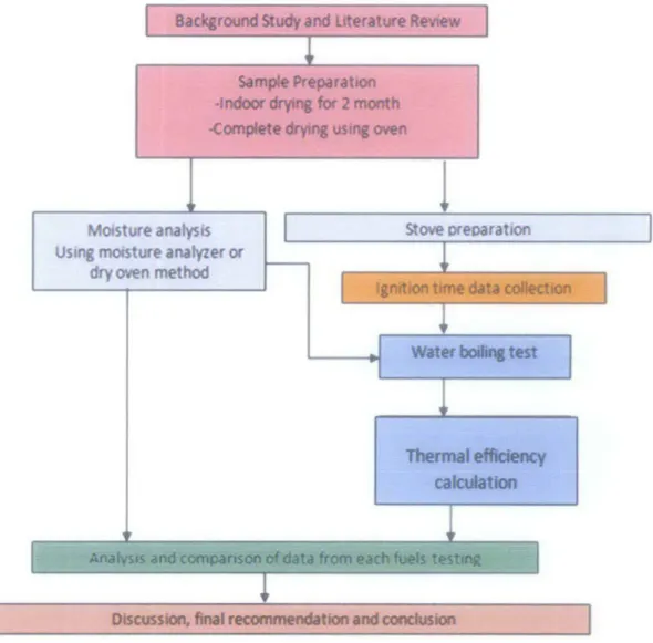
Figure 3.1 shows the overall process flow diagram for the entire project.
Badfaround study and Literature Revtew
Sample Preparation
.fndoOr..,.. for 2 month
-complete~
us-.
CMnMoisture analysis Using moisture analyzer or
dry oven method
Stove oreparat1on
Discussion. flnll recomme11dltton and canduslan
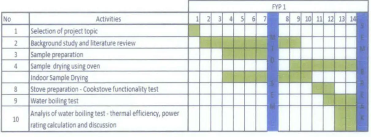
3.2 Project Planning
Figure 3.2 is the Gantt chart of this project which is divided into two academic
semesters, FYP 1 and FYP 2.
11
u
14 17 18 and diSCUSSIOnFigure 3.2: Gantt chart For FYP 1
of water bolhng test· thermal eff1dency, power calculation and d1srussion
on stove Improvement
Final discussion of all results and ecommendation Final Report Submission
Figure 3.3: Gantt chart for FYP 2
FYP 1 focused more on finalizing methodology for the project. This includes finding
all standard procedure of all tests that will be performed. FYP 2 focused on the
experimental parts and completion of this project. Man hour for this project is estimated to be 5 to 6 hours per week.
3.3 System Specification
This project used a gasifer cookstove sold by Chemaco Indonesia as case study. This
cookstove is from the previous research work by Romli (2006) on the best gasifier
Pot Holder
Cover
Ash drawer and air inlet
Figure 3.4: Chemaco biomass cookstove
_j
W
-,
LO
CM
- - - C o n eziTII_ +--- - - - Secondary Ch81!ber
l
llllcM . -Fue I Ch81lber 86c,., II Ocn-
Grate plate 'l3CMI
j
l)Cf\ 2lcM-'
t
.______ ~ Ash Drawerr---, I I I I I I I
~
~
I ~~---~---~j2LITIJ
I l'=-:-::_::-:_=-=--=---::_::-::_::-_=-=_--::_:-::_::-:_'::-=_-=_:-::_::-:_=-=_-=_--::_::-::_-_---:-_...J_ ~ L - - - 'Secondary Chamber Fuel Chamber
r - - - , I I
~
~
I I I 10 I " 1'1 I I Ii
'"00\Le'"
b'/'
J&
L - - - J ConeFigure 3.6: Diagrams of components inside the Chemaco biomass cookstove
The weight of this cook stove was about 23 kg and details dimension where state in
Figure 4.1. There are five main components which are ash drawer, fuel chamber,
grate plat, cone and smaller chamber. The procedure to operate this stove is shown in
Appendix 1.
3.4 Sample Preparation
There were three different fuels prepared for this project. The fuels were oil palm
frond, dry leaves and pressed sugarcane. The main reason of choosing these biomass
fuels is because these are abundance in Malaysia and can be obtained without any
Figure 3.7: Dry leaves Figure 3.8: Oil palm fronds Figure 3.9: Pressed Sugarcane
All the fuels is dried indoor for about 2 months and also dried in an oven for 24
hours at 75°C. The moisture of each sample is inspected and recorded before it can
be used for water boiling test. To make sure the moisture data is accurate, the water boiling test must be conducted within one day after moisture contents testing.
For the 2 month indoor drying, the moisture content of each fuel was checked every week to get it drying rate.The fuels were dried inside closed lab building at room temperature and with natural air circulation. No fan was used to dry the fuels. Result
of drying experiment is shown in Figure 3.10.
60
-so
~..
~ 40..
c 8 30 f.a
20"'
0 ~ 10 1 2 3 4 5 6 Week~OIL PALM FROND ~PRESSED SUGARCANE
Figure 3.10: Fuels drying duration
7 8
DRY LEAVES
A 1 kg sample of every fueJ was tested every week using dry oven method to get the moisture content of the sample. Drying of dry leaves requires the fewest amount of time because the initial moisture content of dry leaves is the lowest. Drying time also influenced by the surface area of the fuel. The larger the surface area of fuel exposed
3.5 Dry Oven Method for Sample Moisture Content
Moisture of fuel can be determined using moisture analyzer. Dry oven method is an
alternative way to measure sample fuel moisture content in case of unavailability of
moisture analyser. This test is used to determine water content by drying a sample at
constant mass at a specified temperature. The water content of a sample is expressed
as percentage of the mass of water to the mass of solid of the sample fuel. Details of
apparatus used and the procedure of this method are shown in Appendix 2. Figure 3.1 0 shows the equipment used for drying process.
Figure 3.10: Oven used for drying process, CARBOLITE 450
3.6 Stove Performance
Stove performance or its efficiency will be determined using water boiling test. The
test was conducted according to Water Boiling Test Version 3.0 developed by
Volunteers In Technical Assistance (VITA) (The Partnership for Clean Indoor Air,
2010). An improved version of Water Boiling Test VITA 1985. 2.5 kg of water was
heated on a cook stove inside a pot without lid. Pot used in this project was a 22 em
aluminium pot. Details on apparatus needed and a procedure for water boiler test is
shown in Appendix 3. Efficiency of stove was calculated using Equation 3 .1.
(3.1)
Where in the equation, Mw; is the mass of water initially in cooking vessel measured
in kg, Cpw is specific heat of water in kJ/kg°C, Mw,evap is mass of water evaporated in
latent heat if evaporation at 1 00°C and 1 05k.Pa, kJ/kg and last but not least H1 is
calorific value of the fuel measured in kJ/kg (Bhakta, 2007). 3. 7 Stove Ignition Time
Small ignition time is favourable for this kind of cookstove. The ignition time was measured from the time fuel inside fuel chamber is ignited until complete combustion of syngas starts to occur inside the fuel chamber.
3.8 Safety during Operation
The outside temperature of the stove during testing is expected to be hot and can accidentally burn users, so it is recommended to use a handle when moving or
handling a hot stove. During the operation of the stove, carbon monoxide was obtained, which is toxic in nature. Therefore, it is recommended not to use the stove
in an enclosed area, i.e.: in a tent, camper or in a house. Subsequently after
completion of the burning period some charcoal is obtained as unbumt fuel. If the stove is closed before charcoal is fully consumed, there are chances that the charcoal remains a frre hazard. Disposal of the charcoal in a safe place where it does not produce a fire or waiting until it cools to a safe temperature is also an important requirement in operating a stove.
3.9 Experiment's Apparatus required
All tools and apparatus required through this entire project is shown in Table 3.1 Table 3.1: Experimental Apparatus
Apparatus Function
SHINI Low Speed Granulator Sample preparation (granulate sample)
Stopwatch Thermometer ~ ·"-. ~----~:-.:···~
---
--. ~ ... ~.;;=--~--Dry OvenGet ignition time and time for water boiling test
Measure ambient air and water temperature
For fuel moisture analysis and drying samples before can be used for water boiling test
Determine calorific value of every biomass fuel used
CHAPTER4
RESULTS AND DISCUSSION
4.1 Water Boiling Test
Cook stove performance using different types of biomass fuel was determined using water boiling test. Each fuels needed to boil 2.5 kg of water. All moisture from the fuels was removed before the experiment began. Water boiling test consist of three main parts, high power test with cold start, high power test with hot start and low power or simmering test. These three tests were important to show that the fuels and stove used are capable of performing all cooking requirements. Parameters taken during the experiments for high phases were recorded in Table 4.1.
Table 4.1: Experimental results from water boiling test
Phase Cold start, high power Cold start, high power
Fuel Oil palm Pressed 50%0PF, Oil palm Pressed 50%0PF,
frond sugarcane 50% dry frond sugarcane 50% dry
Ambient air temperature (0C) 32 32 32 32 32 32
Calorific value (KJ/Kg} 17787 16821 18512 17787 16821 18512
Stove ignition time 14min28s 16 min 34s 17 min08s 8 min 43 s 8 min 26s 9min 16s
Initial water temperature (0C) 28 28 28 28 28 28
Boiling water temperature (0C) 98 99 99 99 99 99
Initial water weight (kg) 2.5 2.5 2.5 2.5 2.5 2.5
Water weight after boiling (kg) 2.05 2.16 2.29 2.02 2.15 2.29
Weight of water evaporated (kg) 0.45 0.34 0.21 0.48 0.35 0.21
Time spend to boil water 23 min 43 s 27 min 24 s 28 min 43 s 8 min 17s 22 min 48s 25 min 32 s
Total fuel consumed (kg) 1.86 2.24 2.89 1.59 2.16 2.63
Efficiency 5.30% 4.02% 2.28% 6.48% 4.23% 2.51%
100% dry leaves did not become one of the fuels because of it low bulk density. The stove fuel chamber capacity cannot support required mass of dry leaves. Syngas produced by dry leaves alone was not enough to produce a good flame for a good heat supply for cooking. Therefore, dry leaves were combined with oil palm frond to increase it thermal efficiency.
Table 4.2: Simmering phase data for water boiling test
Phase Simmering
Fuel Oil palm frond Pressed sugarcane 50% OPF, 50% dry leaves
Boiling temperature (0C) 99 99 99
Temperature after 45 minutes (0C) 79 83 74
Temperature drop after 45 minutes (0C) 20 16 25
For simmering test, the test was not successful for all types of fuel. Requirement for
simmering test is that the fuel able to supply heat to maintain water temperature
inside pot to be within 6°C from boiling temperature for 45 minutes after the water
boiled. All fuels cannot supply enough syngas for the stove to pass through
simmering phase. Discussions on the high power phase test are as the following:
...
~..
I'CI ~ ~""
N 0 .0 0..
c: 0...
I'CI...
;:, 0 0:36:00 0:28:48 0:21:36 0:14:24 0:07:12 0:00:00• Oil palm frond
cold start, high power
Pressed sugarcane
0:25:32
0:22:48
hot start, high power
50% OPF, 50% dry leaves
Figure 4.1: Time required to boil 2.5 kg of water
Test Phase
Time to boil water was recorded from the time flame start until the water inside the
pot was boiled. For both cold and hot start, the fastest fuel to boil water was oil palm
frond followed by pressed sugarcane and mixture of oil palm frond and dry leaves.
During the tests, flames produced by oil palm frond were the biggest and continued
3.5 3 2.89
~
2.5 2.16 2.63 "0 Ql E 2 :1"'
I: 8 1.5 Gi .2 1-
..
0 ..c::: 0.5 .!!!> Ql ~ 0 Test Phasecold start, high power hot start, high power
• Oil palm frond • Pressed sugarcane 50% OPF, SO% dry leaves
Figure 4.2 Weight of fuel consumed to boil2.5 kg of water
Weight of fuel consumed was one of the most important parameter for water boiling test. Amount of fuel consumed related to the calorific values of the fuel. Oil palm frond has the highest calorific value among the three fuels, so weight requirement for oil palm frond was the smallest.
7.00 . . . -6.48 6.00 ~ 5.00 ~ ; 4.00 u
5
3.00 ~.s
2.00"'
1.00 0.00 5.33 _jcold start, high power hot start, high power
Test Phase
• Oil palm frond • Pressed sugarcane 50% OPF, SO% dry leaves
Figure 4.3: Stove efficiency with different types of fuel
The efficiency of the stove range from 2.28% to 5.33% for cold start and 2.51% to 6.48% for hot start. From Figure 4.5, oil palm frond had the highest efficiency with 5.33% for cold start and 6.48% for high start. Hot start phase efficiency relatively higher because for the test, the stove already hot and already has high temperature
stove. This low efficiency was related to the insufficient operation of the stove. Discussion on stove operation can be found in part 4.3.
4.2 Stove Ignition Time
Stove ignition time was recorded from the moment fuels were ignited until flame from syngas was ignited. This parameter was important as users prefers stove that has low ignition time.
0:20:10
-
VIe
0:17:17:5.
c 0:14:24 0 ;;"'
...
:I Q 0:11:31 c 0:08:38 0 ;;~
0:05:46 Cll > 0:02:53 0 ~ 0:00:001
0:16:34 0:17:08cold start, high power
0:09:16 0:08:43 0:08:26
hot start, high power
Test Phase
J
• Oil palm frond • Pressed sugarcane 50% OPF, 50% dry leaves
Figure 4.4: Stove ignition duration
Based on Figure 4.4, the stove ignition duration was in the range of 14 to 27
minutes for cold start and 8 to 9 minutes for hot start. This long ignition duration was not desirable for cooking. Traditional cooking method would only require 1
to 3 minutes for flame ignition. The long ignition duration was due to insufficient
flow of syngas. The syngas produced did not cumulate well, hence the long
4.3 Discussion on Stove Operation
Pot
Secondarv chamber
Fuel chamber
Pot/pan holder
Ash drawer I air inlet
Figure 4.5: Operating Chemaco biomass cookstove
Figure 4.5 shows full images of operating Chemaco biomass gasifier based cookstove. For water boiling test, the stove was treated as partial downdraft gasifier. Syngas be burned instantaneously as it formed. Biomass fuel was filled inside fuel chamber and the secondary chamber before being ignite. To assist ignition, kerosene had been placed on top of the fuels inside secondary chamber. At this time, the ash drawer was fully open to allow complete combustion of fuel takes place. This encourages formation of high temperature fire bed. After enough fire bed formed inside secondary chamber, pot holder and pot was placed on top of the secondary chamber. When enough syngas formed, flame ignited. Figure shows the estimation of gasification process that took place inside fuel chamber.
Flame
Syngas flow
Charcoal zone
Pyrolysis /gasification zone Air flow
Ungasified fuel (drying process)
After fire bed formed, the temperature inside stove increased. The opening of ash drawer was limited only about 2 em. This to make sure only limited supply of oxygen being supplied into the fuel chamber. Drying process took placed to remove any remaining moisture inside feedstock. As the temperature increased, pyrolysis zone established, gasified the biomass fuel and formed syngas.
During the experiment, other gasification methods such as downdraft gasification and updraft gasification also being tested on the stove. Both methods failed to produce flame that continued long enough to boil 2.5 kg of water. Even though partial downdraft gasifier method can provide enough syngas and flames to boil the water, its efficiency is too low. Some of the syngas produced be burned before it cumulated to produce flame. The fuel also prone to complete combustion rather than incomplete combustion that can produce syngas as the stove design did not provide enough control for the air supply. The control merely relies on the opening and closing of the ash drawer.
For this Chemaco cookstove, the air and syngas circulations are bad. This directly affects the amount of syngas formed and the efficient usage of the syngas formed. As shown in Figure 4.8, the only space for air and syngas to circulate is between the
biomass fuels. Large amount of syngas cannot cumulated at the same time, flame produced stayed large only for 10 to 15 seconds. After that only small flame
produced, hence the long boiling time and low efficiency.
To efficiency of the stove can be improved by improving the cookstove design. Gas vent can be installed on the upper part of the fuel chamber as shown in Figure. Instead of burning the syngas directly when it is formed, the syngas travelled back to the top of the stove through the gas vent. This will ensure that enough syngas will always cumulate on the secondary chamber and large continuous fames can be formed.
CHAPTERS
CONCLUSIONS AND RECOMMENDATIONS
5.1 Conclusions
An energy efficient biomass cookstove based on gasification principle need to be developed to maximize energy harvest from biomass in a clean and environmental friendly way. It is expected that the convenience, efficiency and safety advantages offered by developed biomass stove will help to improve living standard of people who depending on biomass as their domestic cooking energy source. Information on current properties of gasifer based cookstove such as thermal efficiency of the fuels used and ignition time are crucial to improved current design.
From water boiling test of Chemaco cookstove, the best fuel to be used was oil palm frond followed by pressed sugarcane and mixture of oil palm frond and dry leaves. Even so, thermal efficiency of the stove is still relative low compare to other method of extracting energy from biomass. The stove is not capable of conducting simmering phase of water boiling test. Improvements on the cookstove design need to be done to increase its efficiency. The project's objectives of evaluating cookstove basic properties and determine which biomass is most suitable to be used with this kind of stove has been achieved.
5.1 Recommendations
This project can be improved by specifically design and implement improvement on the cookstove. This can help to support justification that the inefficiency of the stove is mainly because of the bad air and syngas flow inside the stove. The temperature distribution needed to be taken using thermocouple or thermal camera to verify the gasification zones existed inside the fuel chamber. This was not been done in this project because of lack of time. Most time had been spend on how to get gasification process occurred and good flame using the stove. These temperature distributions will give clearer idea on how the stove works.
REFERENCES
Ale B.B., Bhattarai N., Gautam J., Chapagain P., Pushpa K.C., A sustainable
prospect for institutional cooking, Tribhuvan University
Basu, P., 2009, Biomass Gasification and Pyrolisis, Elsevier Inc.
Bhattacharya, S.C and Leon M.A., 2008, Prospects for Biomass Gasifiers for
Cooking Applications in Asia, Thailand, Asian Institue of Technology
Bhattacharya, S.C., Attalage R.A., Leon M.A., Thanawat. C., 1999, Potential of
Biomass Fuel Conservation in Selected Asian Countries Biomass Energy Data Book, U.S Department of Energy, 2009
Forschungszentzrurn, K.G, 2004, Definition of a standard biomass
Gupta, R., 2009, Pyrolysis Modelling in Wood Stove, International Journal of Engineering Science and Technology
Hennon, F., Tremier A., Debenest G., 2009, A Method To Characterize The
Influence Of Air Distribution On The Composting Treatment: Monitoring Of The Thermal Fields, Global NEST Journal, Volll, No 2, pp 172-180, 2009
Panwar, N. L., 2009, Design and performance evaluation of energy efficient biomass
gasifier based cookstove on multi fuels, 14:627-633
Rajvanshi, A.K, 2006, Biomass Gasification, India, Nimbkar Agriculture Research Institute
Reed, T.B and Larson, R, 1996, A wood-gas Stove for Developing Countries, http://www. bioenergylists.org/ stovesdoc/Reed/T l.htm
Romli, R., 2010, Performance Evaluation of Various Biomasses on an Energy
Efficient Biomass Gasifier Based Cookstove, Final Year Project Dessertation,
Department of Mechanical Engineering, Universiti Teknologi PETRONAS Shepherd, W. and Shepherd, D. W., 2003, Energy Studies, Imperial College Press Slipper H.B., Clifford M.J., Pickering S.J, 2009, Breeding a Better Stove: the Use of
Stove Testing, The Partnership for Clean Indoor air, 2010,
http://www. pciaonline.org/testing
Turare, C, 2002, Biomass Gasification Technology and Utilisation, ARTES Institute
Glucksburg, Germany
Wereko, C.Y and Hagen, B.E, 1996, Biomass Conversion and Technology, England,
John Wiley & Sons
Wood Energy, Institute of Wood Science and Technology, Bangalore, India, 2009,
http://iwst.icfre.gov.in!divisions/we/weindex.html
World Energy Outlook, Energy for Cooking in Developing Countries, International
APPENDICES
APPENDIX 1 : STOVE OPERATION PROCEDURE (Romli, 2010):
1. First of all, the fuel chamber located at the centre of the cook stove will be filling up with a small size of wood chips (the fuels).
n. Next, put in a small amount of the oil palm kernel at the secondary chamber, suit for the usage. Excessive quantity of the oil palm kernel will result massive flame with smoky conditions.
m. Then, open the ash drawer located at the bottom side of the cook stove. Main purpose is for the air ventilation of the cook stove itself.
tv. After this 3 steps, ignite the fuel chamber, which have wood chips inside. v. Wait for the complete combustion process occurred inside the fuel chamber.
Resulting from this activity, we can observe the changeability of the oil palm kernel into an oily state and bum entirely.
VI. After that, place up suitable cooking utensil at the corresponding place upside
the cook stove.
vii. If the biomass resources is not enough for the current process, repeat steps 1 until2 thoroughly.
vn1. For safety reasons, keep the cook stove in a good environment if not in used to avoid any bad circumstances from occurred.
APPENDIX 2 : DRY OVEN TEST
This test is used to determine water content by drying a sample at constant mass a ta a specified temperature. The water content of a sample is expressed as percentage of the mass of water to the mass of solid of the sample fuel.
APPARATUS
I. Weighing device :A balance or scale sensitive to 0.1% of the mass of the test sample, and having a capacity equal to, or greater than, the wet mass of the sample to be tested.
2. Drying device : An oven or other suitable thermostatically controlled heating
3. Containers
TEST PROCEDURE
chamber capable of maintaining a temperature of II 0 ± 5° C. : Any pan or other container that will not be affected by the
drying temperature, and is suitable for retaining the test sample without loss while permitting the water to evaporate.
I. Prepare a representative portion of the material to be tested.
a) Unless other amounts are specified, suggested minimum test sample sizes is 500 g.
b) When testing lightweight, bulky materials, such as straw, hand pack a substantial amount of material into a suitable container having a capacity of approximately 3.8 L.
2. Determine the mass of the test sample and record this mass as "wet mass". 3. Dry to constant mass at 110 ± l5°C.
a) To reduce drying time, break lumps of material into small fractions and spread in a thin layer over the bottom of container. Position the container in a drying device to allow maximum air circulation and exhaust of the moisture laden air.
6. Calculate moisture content using following formula:
mass of water Percent moisture = d f
1 x 100
ry mass o samp e
APPENDIX 3: WATER BOILING TEST VERSION 3.0
EQUIPMENT REQUIRED
a) A pan without lid.
b) Thermometer for measuring the ambient and boiling water temperature. c) A digital balance for measuring the weight of fuel, water and pan
TEST PROCEDURE
1. Weight an quantity of biomass fuel 2. Weigh the pot
3. Fill the pot to 2/3 of capacity with room temperature water. Record the water weight and volume.
4. Record the temperature of the water
5. Start the fire and note the time and temperature
6. Wait for the water to boil, record the water temperature, and weight 7. Remove all unburned fuel from stove and weight it.
8. Calculate weight of water evaporated
CALCULATIONS
The quantity of water evaporated after complete burning of the fuel was determined to calculate the efficiency by using the following formula (Bhakta, 2007).
where in the equation, Mw; is the mass of water initially in cooking vessel measured in kg, Cpw is specific heat of water in kJ/kg°C, Mw,evap is mass of water evaporated in kg, Mt is the mass of fuel burned measured in kg, Te is temperature of boiling water in Celsius ("C), T; is initial temperature of water in pot also in Celsius ("C), H; is latent heat if evaporation at 1 OO"C and 1 05kPa, kJ/kg and last but not least H1 is calorific value of the fuel measured in kJ/kg ..
Data calculation sheet for water boiling test 3.0:
WATER BOIUNG TEST
DATA AND CALCULAnON FORM (tl!efamcan be used with stoves that cook between ooeand four pots)•
Sh8ded cells nM~Uilt! us~ input: un/uKIQd C@/ls BUIDms/ically display CJtJtpfb
Qualitative data Name(s) ofTester(s) Test Number Date Stove t)'Pelmodel Location Type of fuel 'Nine! amdilions
I
(Stltct:ffomlist)Initial Test Conditions
....
Airtemp
Average dimensions of fuel (if solid) Gress caklriftcvalue (dry fuel) Net calorific value (dry fuel) Wood moisture content(%· v.et basis) E ffecti"le calorific ~·alue
(accounting for fuel moisture)
Description of stove am! other comments:
,
.. BASIC liST DATAI " " ' IT;m, ;o I hem;,
-···
Pot# 1'
"
Pot#2"
Pot# 3"
Pot#4"
\•.eter v.eter water (if any)'
value I, f, Tl,, T2" TJ,, T4,, ' ' " ' " P1~ .. P2~ P3= P4, COLD START Calculations/Results 1!.lli: data ~Wood consumed (moist} 1,
Uel change in char during lest
'
t<,Equiwlenl dry I'.OOd consumed
'
\,Water vaporized from .ali pots
'
w,. Efle-ctiYe mass of1•.ater boiled'
\'I:Time tc boil Pot# 1 min
"·
Temp.-corr time to b011 Pot# 1 min ftl,
Thermal ef~ciency % h,
Burning rete g.imin ...
'"
Specific fuel consumption gMer ... sc, T emp...corr sp consum p\icn gll~er SC\
Firepo1.•.er watts FP,
"""
,,..,
"
:I
""'
•rtote. if you are testing a multi-pot stove, the data entry places in the simmering test for pots other than the primary pot are left blank intentionally because the simmering test can not acrount for pols other than the primary pol.
vakle units
"""
DIY \'.eight ofPot11: 1 (grams)cmxcmxcm 01}' ••.eight cfPol# 2 (Srams)
P1 P2 P3 P4 ~,. kJ/kg % kJ/kg
HHV Dry v.eight of Pot# 3 (!!rams} LHV Dry \'.eight of Pot# 4 (!!rams)
m •Neigh! of container fer char (grams)
...
local baiting point;
Pol#f oo;• ~ol#f IDiO
t., " fl. ...•..•....•.. 1.,, '-Tl~ T1 T2:: :::~.::::~:::::~~::
T;::
T3=' .... ----.· .. :· TZ-. T4:: .. _ ... - .... ,_ T4, P1 = .. P1, P2= P2., 1., 1., T1., T2, n. T4.,"·
P2., P:\,"·
:=:~:-~-::·
I· -~-: "· .. ... .. .. ,, 1 ... " · 1- --··· c, I ... c..,'
T, '" ···-:-··-··-···--··· ..'
'
'
!. Tl, T1 0iT,:"'.
',!\':.',':::'!;;:I
. ·n"·
"·
. . .."'-,-,;;.
, I
I -"';~,;::;; "' "'"'•".""HOT START FROt.l HIGH PO'.\IER TEST)
"~ label C.alculations/Results 1\.lli data label
'"
Wood consumed during the simmer phase (n"'
""
ffet change in char during test phase tc,(, Equwalent dry\'.{)O!l consumed \o
'"
Water vaporized \'i-,I··· w., Water remaining at end- Pot# 1
1'.1,.-"·
Time of simmer (should be -4Sminules) mm !>1.,llt'", Thermal efficiency % h,
' " ' "
h, Burning rete g/min
'"
,, SpeQ~cfuel consumption g>1~er sc,
sc, Firepo>•£1' vatts FP,
... seT, Turn CO\I.'Il ratio TDR FP,
Use this worksheet if you are determining fuel moisture with the Oelmhorst J-2000 or similar handheld moistwemeter. If you are using another means to detennine fuel moisture, ignore this worksheet and enter the moisture in the propers pace on each Tesfs data form.
To find fuel moisture, take 3 pieces of fuel at random from the stock used for each test and measure each in three places along its length. Enter the results in the spaces below. The worksheet will autlmaticaUy calculate average moisture content on a dry and wet basis.
Test-1 Instrument reading Test-2 Instrument reading The Demhorst J·2000 moisture analyzer (%dry basis) (%dry basis) me6sures ruel mOisture on a dry basis. To 1 2 3 1 2 3 find moisture on a wet basis. simply use !he following cak:tllation
Piece 1 Piece 1
Piece 2 . Piece 2 . !.!C "' MC",
Piece 3 Piece 3
ThiS spread~ doJtMfsceak::ulation automaticaly. Output from the HH data and
Average ~!.~.u..r.~ .. ~;~ntent (%) Average ~-~I.IJ_f_E) __ c_ontent (%)
results vo;or1::sheet requires moisture content
,. ... , on a wet baSis, so the conversion is very
dry-basis ____ j wet-basis dry-basis :wet-basis! important
... -··---··
·-·-Test-3 Instrument reading (%dry basis)
1 2 3
Piece 1
Piece 2 Piece 3 .
A;erage mJi::;tu~e __ content (%) dry-basis[ } wet-basis!
····--·