UKnowledge
UKnowledge
Theses and Dissertations--Chemical and
Materials Engineering Chemical and Materials Engineering
2017
Synthesis and Energy Applications of Mesoporous Titania Thin
Synthesis and Energy Applications of Mesoporous Titania Thin
Films
Films
Syed Z. IslamUniversity of Kentucky, syedislam@uky.edu Author ORCID Identifier:
http://orcid.org/0000-0002-5149-8094
Digital Object Identifier: https://doi.org/10.13023/ETD.2017.081
Right click to open a feedback form in a new tab to let us know how this document benefits you. Right click to open a feedback form in a new tab to let us know how this document benefits you.
Recommended Citation Recommended Citation
Islam, Syed Z., "Synthesis and Energy Applications of Mesoporous Titania Thin Films" (2017). Theses and Dissertations--Chemical and Materials Engineering. 73.
https://uknowledge.uky.edu/cme_etds/73
This Doctoral Dissertation is brought to you for free and open access by the Chemical and Materials Engineering at UKnowledge. It has been accepted for inclusion in Theses and Dissertations--Chemical and Materials Engineering by an authorized administrator of UKnowledge. For more information, please contact UKnowledge@lsv.uky.edu.
I represent that my thesis or dissertation and abstract are my original work. Proper attribution has been given to all outside sources. I understand that I am solely responsible for obtaining any needed copyright permissions. I have obtained needed written permission statement(s) from the owner(s) of each third-party copyrighted matter to be included in my work, allowing electronic distribution (if such use is not permitted by the fair use doctrine) which will be submitted to UKnowledge as Additional File.
I hereby grant to The University of Kentucky and its agents the irrevocable, non-exclusive, and royalty-free license to archive and make accessible my work in whole or in part in all forms of media, now or hereafter known. I agree that the document mentioned above may be made available immediately for worldwide access unless an embargo applies.
I retain all other ownership rights to the copyright of my work. I also retain the right to use in future works (such as articles or books) all or part of my work. I understand that I am free to register the copyright to my work.
REVIEW, APPROVAL AND ACCEPTANCE REVIEW, APPROVAL AND ACCEPTANCE
The document mentioned above has been reviewed and accepted by the student’s advisor, on behalf of the advisory committee, and by the Director of Graduate Studies (DGS), on behalf of the program; we verify that this is the final, approved version of the student’s thesis including all changes required by the advisory committee. The undersigned agree to abide by the statements above.
Syed Z. Islam, Student Dr. Stephen E. Rankin, Major Professor Dr. Thomas D. Dziubla, Director of Graduate Studies
___________________________________ DISSERTATION
____________________________________ A dissertation submitted in partial fulfillment of the requirements for the degree of Doctor of Philosophy in the
College of Engineering at the University of Kentucky
By Syed Z. Islam Lexington, Kentucky
Director: Dr. Stephen E. Rankin, Professor of Chemical Engineering Lexington, Kentucky
2017
ABSTRACT OF DISSERTATION
SYNTHESIS AND ENERGY APPLICATIONS OF MESOPOROUS TITANIA THIN FILMS
The optical and electronic properties of TiO2 thin films provide tremendous
opportunities in several applications including photocatalysis, photovoltaics and photoconductors for energy production. Despite many attractive features of TiO2, critical
challenges include the innate inability of TiO2 to absorb visible light and the fast
recombination of photoexcited charge carriers. In this study, mesoporous TiO2 thin films
are modified by doping using hydrogen and nitrogen, and sensitization using graphene quantum dot sensitization.
For all of these modifiers, well-ordered mesoporous titania films were synthesized by surfactant templated sol-gel process. Two methods: hydrazine and plasma treatments have been developed for nitrogen and hydrogen doping in the mesoporous titania films for band gap reduction, visible light absorption and enhancement of photocatalytic activity. The hydrazine treatment in mesoporous titania thin films suggests that hydrazine induced doping is a promising approach to enable synergistic incorporation of N and Ti3+ into the lattice of surfactant-templated TiO2 films and enhanced visible light photoactivity, but that the benefits are limited by gradual mesostructure deterioration. The plasma treated nitrogen doped mesoporous titania showed about 240 times higher photoactivity compared to undoped film in hydrogen production from photoelectrochemical water splitting under visible light illumination.
Plasma treated hydrogen doped mesoporous titania thin films has also been developed for enhancement of visible light absorption. Hydrogen treatment has been shown to turn titania (normally bright white) black, indicating vastly improved visible light absorption. The cause of the color change and its effectiveness for photocatalysis remain open questions. For the first time, we showed that a significant amount of hydrogen is incorporated in hydrogen plasma treated mesoporous titania films by neutron reflectometry measurements.
In addition to the intrinsic modification of titania by doping, graphene quantum dot sensitization in mesoporous titania film was also investigated for visible light photocatalysis. Graphene quantum dot sensitization and nitrogen doping of ordered mesoporous titania films showed synergistic effect in water splitting due to high surface area, band gap reduction, enhanced visible light absorption, and efficient charge separation and transport. This study suggests that plasma based doping and graphene quantum dot sensitization are promising strategies to reduce band gap and enhance visible light absorption of high surface area surfactant templated mesoporous titania films, leading to
composite nanomaterials for fundamentally improving visible light absorption, charge separation and transport, and thereby photoelectrochemical properties.
KEYWORDS: mesoporous; titania thin films; nitrogen doping; hydrogen doping; photocatalysis; surfactant templated sol-gel
Syed Z. Islam Student’s Signature
4/14/2017 Date
SYNTHESIS AND ENERGY APPLICATIONS OF MESOPOROUS TITANIA THIN FILMS By Syed Z. Islam Stephen E. Rankin, PhD Director of Dissertation Thomas D. Dziubla, PhD Director of Graduate Studies
iii
ACKNOWLEDGEMENTS
Praise be to God who has blessed me to take on this journey. I am grateful to everybody who have in one way or other contributed to this journey. The first and foremost, I would like to present my utmost gratefulness towards my PhD supervisor, Dr. Stephen E. Rankin, for his guidance and mentorship throughout my graduate study. The helps and supports that Dr. Rankin has provided with extraordinary patience during each step of this research could not be measured. His guidance throughout my graduate career has proven to be invaluable and his dedication to the education of his students is unparalleled. One of things I have joyed most working with him is the independence he has given me to work on my research, which will provide me with confidence in every endeavors in my life. He has been a great mentor and leader. I wish to have my future mentors as good as Dr. Rankin.
I would like to express my sincere thanks to all my dissertation committee members Dr. Barbara L. Knutson, Dr. Brad Berron and Dr. Doo-Young Kim for being accessible at any point in time. I thank the members for their comments about my proposed research during the early times of the proposal defense and yearly committee meetings, which helped to improve several of the experiments and analyses performed to complete this dissertation. Their questions, comments and suggestions regarding this research during those meetings really helped me think in different perspectives. I would like to acknowledge and show my deep appreciation to our collaborators Dr. Doo-Young Kim, a professor of Chemistry department at UK, Allen Reed and Namal Wanninayake from Dr. Kim’s group for providing me with plasma system and graphene quantum dots. This research would be incomplete without their ingenious support. Other than that, the guidance from Dr. Doo-Young Kim was tremendously helpful in formulating my research. My sincerely appreciation goes to Dr. Barbara L. Knutson for her valuable suggestions and
iv
guidance throughout my graduate study from course work to research. Also, her suggestions during our group meeting was really helpful. I would like to thank Dr. Brad Berron for taking the time to actively participate in my dissertation committee and provide valuable feedback during the proposal and yearly committee meetings.
I would like to thank Nicholas Briot and Dali Qian from the Electron Microscopy Facility for their help with SEM and TEM characterizations. I would also like to thank Mr. Jason Backus from Kentucky Geological Survey for help with XRD instrument. The help from Dr. Joseph W Strzalka at Argonne National Laboratory with analyzing our samples through GISAXS and GIWAXS is greatly appreciated. I really appreciate the opportunity my lab member, Suraj Nagpure gave me to work with him in Oak Ridge National Laboratory to perform neutron reflectivity under his allotted beam time. I would also like to thank Dr. James Browning at Oak Ridge National Laboratory for his help to analyze neutron reflectometry data. I thank Prof. Y.T. Cheng, Prof. Dibakar Bhattacharyya and Andrew Colburn, and Prof. Brad Berron and Ishan Fursule, Prof. Anne-Frances Miller and Dr. Rupam Sarma, and Prof. Vijay Singh and Sai Guduru for access and assistance with the XPS, zeta potential, contact angle measurements, oxygen measurement, and water oxidation using the Xe arc lamp, respectively. I would also like to thank all my previous and current lab members; specially Dr. Suvid Joshi, Dr. Ravinder Garlapalli, Dr. Saikat Das, Dr. Suraj Nagpure, Dr. Daniel M. Schlipf, Md. Arif Khan, Shanshan Zhou, Yuxin He and Mahsa Moradipour. Without their assistance in the lab it would not have been possible to complete this research successfully and in a timely manner, and would not have a great time in this graduate study. I would like to extend my gratitude to our departmental staff
v
Ms. Chelsea Hansing, Ms. Marlene Spurlock, Ms. Melissia Witt, Ms. Nancy Miller and Mr. Bruce Cole for being extremely efficient and supportive.
I acknowledge the financial support to accomplish this work from U.S. Department of Energy EPSCoR Implementation award supported by grant no. DE-FG02-07-ER46375 and National Science Foundation EPSCoR Research Infrastructure Initiative award supported by grant no. IIA-1355438. I am very grateful to Professor Dibakar Bhattacharyya for giving me funding from NSF EPSCoR. I acknowledge the Dissertation Enhancement Award from UK. I also acknowledge the Liquids Reflectometer facility at the Spallation Neutron Source, which is sponsored by the Scientific User Facilities Division, Office of Basic Energy Sciences, U.S. DOE (J.F.B., J.K.K.) and the GISAXS and GIWAXS facilities of the Advanced Photon Source, a U.S. Department of Energy (DOE) Office of Science User Facility operated for the DOE Office of Science by Argonne National Laboratory under Contract No. DE-AC02-06CH11357.
My sincerely gratitude goes to my former lab member and roommate, Saikat Das and present roommate, Riasad Azim Badhan for providing me a congenial atmosphere and their support at home. My special thanks go to all of my friends across the world, especially Rupam Sarma, Moushumi Sarma, Md. Arif Khan, Nirupam Aich, Md. Ariful Hoque and Md. Monir Uddin for support and friendship.
Lastly, I would like to acknowledge the most important persons in my life who are my mother, brothers, sisters, nieces and nephews for their perennial love and support throughout my entire life. I have deprived them from meeting me for last seven years. I am very sorry for that. Their unreturnable sacrifices have brought me here today.
vi
TABLE OF CONTENTS
ACKNOWLEDGEMENTS ... iii
TABLE OF CONTENTS ... vi
LIST OF FIGURES ... xi
LIST OF TABLES ... xviii
Chapter 1. Introduction ... 1
1.1. Background and Motivation ... 1
1.2. Hydrogen production from water splitting ... 2
1.3. Titania as a Photocatalyst ... 4
1.4. Nanostructured Titania ... 5
1.5. Doping of Titania ... 6
1.6. Sensitization of Titania ... 8
1.7. Overview and Summary of the Dissertation ... 10
Chapter 2. Synthesis and Catalytic Applications of Non-metal Doped Mesoporous Titania ... 18
2.1 Summary ... 18
2.2. Introduction ... 19
2.2.1. Synthesis of mesoporous TiO2 ... 25
2.2.2. Titanium Precursor Chemistry ... 26
2.2.3. Surfactant-templated Film Deposition ... 29
2.2.4. Surfactant/Titania Film Aging ... 32
2.2.5. Thermal Treatment ... 35
2.3. Nitrogen doping... 37
2.3.1. Amines ... 38
vii
2.3.3. Hydrazine ... 41
2.3.4. Plasma Doping ... 42
2.3.5. Thiourea ... 43
2.3.6. Urea ... 44
2.3.7. Summary of Nitrogen Doped Mesoporous Titania ... 46
2.4. Other non-metal doped mesoporous titania ... 49
2.4.1. Hydrogenation... 49 2.4.2. Boron doping ... 50 2.4.3. Carbon doping ... 51 2.4.4. Fluorine doping ... 53 2.4.5. Iodine doping ... 55 2.4.6. Phosphorus doping ... 56
2.4.7. Summary of Nonmetal Dopants other than Nitrogen ... 58
2.5. Co-doping of non-metals ... 59 2.6. Applications ... 63 2.6.1. Water Splitting ... 63 2.6.2. CO2 Reduction ... 67 2.7. Future Directions ... 69 2.8. Conclusion ... 71
Chapter 3. Hydrazine-based Synergistic Ti(III)/N Doping of Surfactant-Templated TiO2 Thin Films for Enhanced Visible Light Photocatalysis ... 85
3.1 Summary ... 85
3.2 Introduction ... 86
3.3. Experimental ... 89
viii
3.3.2. Synthesis of mesoporous titania films ... 90
3.3.3. Characterization ... 91
3.3.4. Photocatalytic testing ... 92
3.3.5. Photoelectrochemical testing ... 93
3.4. Results and discussion ... 93
3.5. Conclusions ... 108
Chapter 4. N2/Ar Plasma Induced Doping of Ordered Mesoporous TiO2 Thin Films for Visible Light Active Photocatalysis ... 120
4.1. Summary ... 120
4.2. Introduction ... 121
4.3. Experimental ... 124
4.3.1. Materials ... 124
4.3.2. Synthesis of mesoporous titania films ... 124
4.3.3. N2/Ar Plasma treatment of mesoporous TiO2 film ... 125
4.3.4. Characterization ... 125
4.3.5. Photocatalytic measurement ... 126
4.4. Results and discussion ... 127
4.5. Conclusions ... 137
Chapter 5. Remarkable Enhancement of Photocatalytic Water Oxidation in N2/Ar Plasma Treated, Mesoporous TiO2 Films ... 144
4.1. Summary ... 144
5.2 Introduction ... 145
5.3 Experimental Section ... 149
5.3.1 Materials ... 149
5.3.2. Synthesis of mesoporous titania films ... 149
ix
5.3.4. Characterization ... 150
5.3.5. Photoelectrochemical measurements ... 151
5.3.6. Zeta potential (ζ) measurements ... 153
5.3.7. Contact angle measurements ... 154
5.4. Results and Discussion ... 154
5.5. Conclusion ... 171
Chapter 6. Synergistic Effects of Graphene Quantum Dot Sensitization and Nitrogen Doping of Mesoporous TiO2 Films for Water Oxidation Photocatalysis ... 179
6.1. Summary ... 179
6.2. Introduction ... 180
6.3. Experimental Section ... 183
6.3.1. Materials ... 183
6.3.2. Synthesis of mesoporous titania films ... 184
6.3.3. N2/Ar plasma treatment of mesoporous TiO2 film ... 185
6.3.4. Synthesis of GQDs ... 185
6.3.5. Attachment of GQDs to TiO2 and nitrogen doped TiO2 ... 186
6.3.6. Characterization ... 186
6.3.7. Photoelectrochemical measurements ... 188
6.4. Results and Discussion ... 189
6.5. Conclusion ... 201
Chapter 7. Plasma Treated Hydrogen Doped Mesoporous Black TiO2 Thin Films for Water Oxidation Photocatalysis ... 214
7.1. Summary ... 214
7.2. Introduction ... 215
7.3. Experimental Section ... 221
x
7.3.2. Synthesis of mesoporous titania films ... 221
7.3.3. H2 Plasma Treatment ... 222
7.3.4. Characterization ... 222
7.3.5. Photoelectrochemical characterization ... 226
7.4. Results and Discussion ... 227
7.5. Conclusion ... 238
Chapter 8. Conclusions and Future Work ... 246
8.1. Conclusions ... 246
8.2. Future Work ... 251
APPENDIX ... 258
APPENDIX A Supporting Information of Chapter 3 ... 258
APPENDIX B Supporting Information of Chapter 4 ... 270
APPENDIX C Supporting Information of Chapter 5. ... 279
APPENDIX D Supporting Information of Chapter 6. ... 288
APPENDIX E Supporting Information of Chapter 7. ... 295
References ... 300
xi
LIST OF FIGURES
Figure 1.1. Basic principle of the overall water-splitting reaction on a semiconductor photocatalyst. Adapted from ref. [70]. ... 16
Figure 1.2. Band positions of several semiconductors in contact with aqueous electrolyte at pH 1. The lower edge of the conduction band (red colour) and upper edge of the valence band (green colour) are presented along with the band gap in electron volts. The energy scale is indicated in electron volts using the normal hydrogen electrode (NHE) as a reference. Note that the ordinate presents internal and not free energy. The free energy of an electron–hole pair is smaller than the band gap energy due to the translational entropy of the electrons and holes in the conduction and valence band, respectively. On the right side, the standard potentials of water redox couple are presented against the standard hydrogen electrode potential. Adapted from reference [14]. ... 16
Figure 1.3. Schematic of band diagram of sensitization of titania by small band gap semiconductors. ... 17
Figure 2.1. Schematic representation of Kohn-Sham one-electron states and spin density plot of substitutionally doped anatase TiO2. Reprinted with permission from ref [73].
Reprinted from Catalysis Today vol. 206, C. Di Valentin and G. Pacchioni, “Trends in non-metal doping of anatase TiO2: B, C, N and F,” pp. 12-18, Copyright (2013), with
permission from Elsevier. ... 74
Figure 2.2. Computer-generated illustrations of typical mesoporous structures and mesophases. Clockwise from lower left are illustrated an Im3m cubic mesoporous material, o-HCP mesoporous film, parallel HCP mesoporous film, and lamellar mesophase where higher intensity (yellow and red) corresponds to a greater density of hydrophobic tails of the surfactant template. ... 74
Figure 2.3. Schematics of the important stages of the formation of ordered nanoporous metal oxide films by EISA: (a) The dip coating process in which surfactant micelles form and may begin to assemble due to evaporation, (b) the aging process after deposition in which films organize into an ordered mesophase, and (c) high-temperature aging during which organic templates are removed by oxidation, crystallization may occur but loss of mesostructural order can happen with increasing temperature and time. Part (a) is reproduce with permission from C.J. Brinker et al. [115], (b) shows the rise of intensity
xii
from a o-HCP mesophase in a TiO2 film during aging, adapted from Nagpure et al.[103]
and (c) shows the loss of intensity of the o-HCP mesophase during heating of a TiO2 film
at 600 °C, adapted from Das et al.[105] ... 75
Figure 2.4. Schematic of procedures for preparing mesoporous nitrogen-modified titania photocatalyst. Reprinted with permission from ref. [178]. Reprinted from Chemical Engineering Journal vol. 219, J. Fu et al., “Soft-chemical synthesis of mesoporous nitrogen-modified titania with superior photocatalytic performance under visible light irradiation,” pp. 155-161, Copyright (2013), with permission from Elsevier. ... 75
Figure 2.5. Methylene blue degradation reaction with undoped TiO2 (0 min) film, N-TiO2
films and without films (Photolysis): (a) Concentration profile (b) the plot of the first-order rate coefficient vs. plasma treatment time. Reprinted with permission from ref. [69]. Reprinted from Microporous and Mesoporous Materials vol. 220, S.Z. Islam et al., “N2/Ar
plasma induced doping of ordered mesoporous TiO2 thin films for visible light active
photocatalysis,” pp. 120-128, Copyright (2018), with permission from Elsevier. ... 76
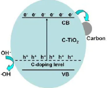
Figure 2.6. Proposed photocatalytic mechanism over the C-TiO2 samples. Reprinted with
permission from ref. [47]. Reprinted from Applied Catalysis B vol. 115, Y. Zhang et al., “Ethanol supercritical route for fabricating bimodal carbon modified mesoporous TiO2
with enhanced photocatalytic capability in degrading phenol,” pp. 236-244, Copyright (2012), with permission from Elsevier. ... 77
Figure 2.7. SEM images of F-mp-TiO2 microspheres synthesized in (a) 0.1, (b) 0.3, (c)
0.5, (d) 0.8, and (e) 1.0% H2SO4 solution. Panel f and the insert of panel a are TEM images
corresponding to hollow (e) and solid (a) microspheres, respectively. Reprinted with permission from ref. [227]. Reprinted with permission from Journal of the American Chemical Society vol. 130, J.H. Pan et al., “Self-etching reconstruction of hierarchically mesoporous F-TiO2 hollow microspherical photocatalyst for concurrent membrane water
purifications,” pp. 11256-7, Copyright (2008) American Chemical Society. ... 77
Figure 2.8. Schematic diagram for generation and transfer of charge carriers in F-TiO2
under UV irradiation. Reprinted with permission from ref [229]. Reprinted with permission from The Journal of Physical Chemistry C vol. 113, J. Yu et al., “Enhancement of photocatalytic activity of mesoporous TiO2 powders by hydrothermal surface fluorination
xiii
Figure 2.9. The transformation of surface structures of B,N-TiO2. Reprinted with
permission from ref. [242]. Reprinted from Journal of Solid State Chemistry vol. 184, X. Zhou et al., “Effect of nitrogen-doping temperature on the structure and photocatalytic activity of the B,N-doped TiO2,” pp. 134-140, Copyright (2011) with permission from
Elsevier. ... 78
Figure 2.10. Basic principle of the overall water-splitting reaction on a semiconductor photocatalyst. Adapted from ref. [70]. ... 79
Figure 2.11. Schematic illustrations of synthesis procedure for CNMT-x samples. Reprinted with permission from ref. [48]. Reprinted from International Journal of Hydrogen Energy vol. 38, S.-H. Liu and H.-R. Syu, “High visible-light photocatalytic hydrogen evolution of C,N-codoped mesoporous TiO2 nanoparticles prepared via an
ionic-liquid-template approach,” pp. 13856-13865, Copyright (2013) with permission from Elsevier. ... 79
Figure 2.12. The mechanism of photocatalytic reduction of CO2 under visible light
irradiation. Adapted from ref. [254]. ... 80
Figure 3.1. Electron micrographs of the F127-templated TiO2 film after calcination and without hydrazine treatment: (a) SEM image of the top surface, (b) TEM image of material scraped from the glass substrate, and (c) XRD pattern of TiO2 film on the original substrate.
... 111
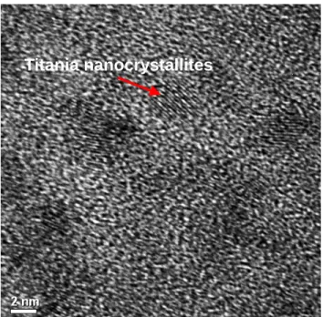
Figure 3.2. HRTEM image of undoped titania film. ... 111
Figure 3.3. (a) UV-vis spectra of undoped TiO2 and Ti3+-N-TiO2 films prepared using
different hydrazine treatment times (the inset shows an enlarged region in the visible wavelength range) and (b) band gap vs. hydrazine treatment time based on Tauc plot analysis. ... 112
Figure 3.4. (a) High resolution N 1s XPS spectra, (b) XPS N 1s depth profile spectra for 5 h_Ti3+-N-TiO2 film, and (c) plot of nitrogen content from XPS depth profile vs. total Ar
etching time at 1000 eV power. ... 113
Figure 3.5. XPS Ti 2p depth profile spectra of (a) undoped TiO2 films and (b) 5 h_Ti3+
xiv
Figure 3.6. Methylene blue degradation kinetics with undoped TiO2 (0 h) films, Ti3+
-N-TiO2 films, and solution without catalysis (Photolysis): (a) Concentration profile, and (b)
pseudo-first order rate coefficient vs. hydrazine treatment time. ... 115
Figure 3.7. Plan view SEM images of (a) undoped TiO2, (b) 5 h_Ti3+-N-TiO2, (c) 10
h_Ti3+-N-TiO2, and (d) 20 h_ Ti3+-N-TiO2 films (Scale bar: 120 nm). ... 116 Figure 3.8. Concentration profiles during methylene blue degradation with 10 h_Ti3+ -N-TiO2 films showing (a) effect of calcination temperature of titania films, (b) effect of
calcination time of titania films and (c) effect of light sources (BLED and UVLED). .. 117
Figure 3.9. (a) Current density as a function of time for the water oxidation reaction with TiO2 and Ti3+-N-TiO2 films (The inset is an expansion of the region from 400 to 1800 s)
and (b) Photocurrent per mass of undoped TiO2 and Ti3+-N-TiO2 films at 600 s as a function
of hydrazine treatment time. ... 118
Figure 3.10. (a) Mott-Schottky plots for undoped TiO2 and Ti3+-N-TiO2 films, and (b) flat
band potential and (c) charge carrier density of the films as a function of hydrazine treatment time. ... 119
Figure 4.1. Schematic of the plasma reactor used for nitrogen doping of TiO2 films. .. 139 Figure 4.2. Electron micrographs of the F127-templated TiO2 film after calcination and
without plasma treatment: (a) SEM image of the top surface, (b) TEM image of material scraped from the glass substrate, (c) cross sectional bright-field STEM image and (d) XRD pattern of TiO2 film on the original substrate. ... 139 Figure 4.3. (a) UV-vis spectra of undoped TiO2 and N-TiO2 films prepared using different
plasma treatment time (inset is a photograph of undoped TiO2 and 30 min_N-TiO2 film)
and (b) Band gap vs. plasma treatment time based on analysis using Tauc plots. ... 140
Figure 4.4. (a) High resolution N 1s XPS spectra, (b) plot of surface N content from XPS vs. plasma treatment time, and (c) XPS N 1s depth profile for the 90 min_N-TiO2 sample.
... 141
Figure 4.5. Valence band XPS spectra (inset is the enlarged region near the band edge) of undoped TiO2 and N-TiO2 films. ... 142 Figure 4.6. Methylene blue degradation reaction with undoped TiO2 (0 min) film, N-TiO2
films and without films (Photolysis): (a) Concentration profile (b) the plot of the first-order rate coefficient vs. plasma treatment time. ... 143
xv
Figure 4.7. SEM images of (a,b) undoped TiO2, (c, d) 30 min_N-TiO2 and (e, f) 210
min_N-TiO2 films. ... 143 Figure 5.1. Schematic of the plasma reactor used for N2/Ar plasma treatment of TiO2 films.
... 172
Figure 5.2. UV-vis absorption spectra of undoped and N-doped TiO2 films prepared with
different nitrogen gas flow rate (0-100 sccm) in the plasma reactor at 70 torr. The inset shows photographs of the corresponding 0 sccm_N-TiO2, 40 sccm_N-TiO2, 60
sccm_N-TiO2, 80 sccm_N-TiO2 and 100 sccm_N-TiO2 films (from left to right). ... 172 Figure 5.3. (a) High resolution N 1s XPS spectra, (b) plot of surface N content from XPS vs. nitrogen flow rate in the plasma reactor, (c) XPS N 1s depth profile for the 100 sccm_N-TiO2 sample and (d) high resolution Ti 2p XPS spectra. ... 173 Figure 5.4. Valence band XPS spectra of undoped TiO2 and N-TiO2 films. ... 173 Figure 5.5. SEM images of (a) 0 sccm_N-TiO2, (b) 40 sccm_N-TiO2, (C) 60
sccm_N-TiO2, (d) 80 sccm_N-TiO2 and (e) 100 sccm_N-TiO2 films (Scale bar = 100 nm). ... 174 Figure 5.6. Zeta potential (ζ) of the undoped TiO2 and 100 sccm_N-TiO2 thin films as a
function of pH. ... 174
Figure 5.7. The effect of plasma treatment conditions on photocatalytic current-time (i-t) profiles under halogen lamp illumination representing water oxidation reaction (a) with a gas pressure variation and (b) with a different N2 gas flow rate in the plasma reactor. . 175 Figure 5.8. Amperometric current-time profiles with 0 sccm_N-TiO2 (undoped) and 100
sccm_N-TiO2 films under the illumination of (a) Xe arc lamp with AM 1.5 G filter (b)
UVLED, (c) BLED and (d) GLED. ... 176
Figure 5.9. Linear sweep voltammetric (LSV) curves recorded with 0 sccm_N-TiO2
(undoped) and 100 sccm_N-TiO2 films under the illumination of (a) Xe arc lamp with AM
1.5 G filter, (b) UVLED, (c) BLED and (d) GLED. ... 177
Figure 5.10. (a) Mott-Schottky plot and (b) Nyquist plot recorded for 0 sccm_N-TiO2 and
100 sccm_N-TiO2 films. ... 178 Figure 6.1. Synthesis steps of (a) graphene quantum dots, and (b) graphene quantum dot sensitized nitrogen doped mesoporous titania thin films ... 204
Figure 6.2. (a). UV-VIS absorbance, (b). Fluorescence, (c) low resolution and high-resolution TEM images and (d) FTIR spectrum of graphene quantum dots ... 205
xvi
Figure 6.3. UV-vis spectra of pure TiO2, GQD/TiO2, N-TiO2 and GQD/N-TiO2 films.206 Figure 6.4. SEM images of (a) undoped TiO2, (b) GQD/TiO2, (c) N-TiO2 films and (d)
GQD/N-TiO2 films... 206
Figure 6.5. GISAXS patterns of (a) undoped TiO2 and (b) N-TiO2 films ... 207
Figure 6.6. (a) High resolution (a) C 1s and (b) N 1s XPS spectra of TiO2, GQD/TiO2, N-TiO2 and GQD/N-TiO2 films ... 208
Figure 6.7. Zeta potential (ζ) of the undoped TiO2 and GQD/TiO2, N-TiO2 and GQD/N-TiO2 films as a function of pH. ... 209
Figure 6.8. Amperometric current-time profiles with undoped TiO2, GQD/TiO2, N-TiO2 and GQD/N-TiO2 films under the illumination of (a) BLED and (b) halogen bulb. ... 209
Figure 6.9. Linear sweep voltammetric (LSV) curves recorded with undoped TiO2 and GQD/TiO2, N-TiO2 and GQD/N-TiO2 films under the illumination of (a) BLED and (b) Halogen bulb. ... 210
Figure 6.10. Linear fit for the ln(R) vs time curve considering only the linear portion with (a) TiO2, (b) GQD/TiO2, (c) N-TiO2 and (d) GQD/N-TiO2 film ... 211
Figure 6.11. Nyquist plot recorded for TiO2, N-TiO2, GQD/TiO2 and GQD/N-TiO2 films ... 211
Figure 6.12. Energy band diagram for GQD/TiO2 and GQD/N-TiO2 ... 212
Figure 7.1. Schematic of the plasma reactor used for H2 plasma treatment of TiO2 films. ... 240
Figure 7.2. UV-vis spectra of mesoporous undoped TiO2 and H-TiO2 films ... 240
Figure 7.3. SEM images of (a) undoped TiO2 and (b) H-TiO2 films ... 241
Figure 7.4. GISAXS patterns of (a) undoped TiO2 and (b) H-TiO2 films ... 242
Figure 7.5. GIWAXS line cut patterns of undoped TiO2, H-TiO2 and anatase TiO2 (calcined at 600 °C for 60 min) films. Integrated line-cut profiles of x-ray intensity vs. qy were computed from the 2D GIWAXS patterns along angular direction (90°<ф>180°) at a fixed range of qy values using GIXSGUI package. ... 242
Figure 7.6. (a) Ti 2p and (b) O 1s high resolution XPS spectra of undoped TiO2 and H-TiO2 films... 243
Figure 7.7. NR profile of H-doped mesoporous TiO2 film in air. The inset shows the scattering length density (SLD) profile of the fitted model. ... 244
xvii
Figure 7.8. NR profile of undoped mesoporous TiO2 film in D2O. The inset shows the
scattering length density (SLD) profile of the fitted model. ... 244
Figure 7.9. Zeta potential measurements of undoped TiO2 and H-TiO2 films ... 244 Figure 7.10. Photocurrent-time measurement with undoped TiO2 film and H-TiO2 films
under (a) UVLED and (b) BLED light irradiation... 245
Figure 7.11. Nyquist plot of TiO2 and H-TiO2 films (Inset shows enlarged plot). ... 245 Figure 8.1. Preliminary test of masking with a fractured Si wafer for (a) H-doping and (b) N-doping. A line scan by XPS of the N-doped interface. ... 256
Figure 8.2. XPS N1s spectra of N-TiO2 film prepared by masking some portions of the
film (line scan was performed) (small scale). ... 257
Figure 8.3. An untreated TiO2 film (left) compared to a dopamine treated TiO2 film (right).
xviii
LIST OF TABLES
Table 2.1. Synthesis method, dopant source, chemical, optical and photocatalytic properties of nitrogen doped mesoporous titania. ... 81
Table 2.1. Synthesis method, dopant source, chemical, optical and photocatalytic properties of nitrogen doped mesoporous titania (Continued). ... 82
Table 2.2. Synthesis method, dopant source, chemical, optical and photocatalytic properties of non-metal doped mesoporous titania. ... 83
Table 2.3. Synthesis method, dopant source, chemical, optical and photocatalytic properties of non-metal co-doped mp-TiO2. ... 84 Table 6.1. Photoelectrochemical water oxidation performance of titania films in amperometric i-t measurements ... 212
Table 6.2. Photoelectrochemical water oxidation performance of titania films in linear sweep voltammetry measurements (currents are taken at 0.35 V vs. Ag/AgCl) ... 212
Table 6.3. Charge recombination rate constants for TiO2, GQD/TiO2, N-TiO2 and
1
Chapter 1. Introduction 1.1. Background and Motivation
Recently, growing energy demand, depletion of fossil fuel and harmful effect of traditional energy sources on the global climate and environment have become profound concerns [1]. As time passes, both the global population and worldwide energy demand increase tremendously. For example, according to the United Nations forecasts, another 2.5 million people are expected to be added to the present population of 6.5 billion by 2050 which will cause the energy demand to double over current demand [2, 3]. Even though the primary energy sources used currently are hydrocarbon-based fossil fuels with limited supply, they are causing serious environmental concerns such as climate change due to atmospheric CO2 emission [4-8]. According to the U.S. Energy Information
Administration, 1 billion barrels of oil were consumed every 12 days in 2011, which would result in 1 trillion pounds of CO2 release to the atmosphere [9]. According to the prediction
of the Intergovernmental Panel on Climate Change, the atmospheric CO2 level could reach
as high as 590 ppm by 2100 , resulting in a 1.9 °C rise in global mean temperature [4, 10]. This temperature rise will have catastrophic consequences including sea level rise, flood and drought. Because of this, it has become a grand challenge to reduce atmospheric CO2
levels while at the same time fulfilling the huge energy demanded for a high quality of life. To tackle these global concerns, intensive research is going on to find clean and renewable energy sources. Renewable energy technologies including solar, hydro and wind power are all possible options to reduce the use of limited and climate change-inducing fossil fuels. However, all of these technologies are based on energy sources with variable intensity, and cannot be used directly for continuous electricity production at a single site.
2
Therefore, it is also pressing to find an efficient and economically viable technology for storable renewable energy so that it can be delivered on demand.
1.2. Hydrogen production from water splitting
Hydrogen has tremendous potential to become an environmentally-friendly fuel, in addition to its ever-growing demand in the petrochemical, refining, and semiconductor industries. Hydrogen is one of the greenest energy carriers, in that it produces only water when oxidized either by combustion or in a fuel cell. It also is a widely used raw material for chemical conversions and reduction reactions. However, production of hydrogen in required quantities at a competitive price has been a crucial and urgent challenge [11]. Hydrogen can be produced from water splitting using electrolysis by the following reactions.
𝐴𝐴𝐴𝐴𝐴𝐴𝐴𝐴𝐴𝐴: 2𝐻𝐻2𝑂𝑂(𝑙𝑙)→ 𝑂𝑂2(𝑔𝑔) + 4𝐻𝐻+(𝑎𝑎𝑎𝑎) + 4𝐴𝐴− 𝐸𝐸𝑜𝑜𝑜𝑜0 = −1.23𝑉𝑉
𝐶𝐶𝑎𝑎𝐶𝐶ℎ𝐴𝐴𝐴𝐴𝐴𝐴: 2𝐻𝐻+(𝑎𝑎𝑎𝑎) + 2𝐴𝐴− → 𝐻𝐻
2(𝑔𝑔) 𝐸𝐸𝑟𝑟𝑟𝑟𝑟𝑟0 = 0.0𝑉𝑉
The first reaction and second reaction are called the oxygen evolution reaction (OER) and hydrogen evolution reaction (HER), respectively. The standard potentials of the half reactions (𝐸𝐸𝑐𝑐𝑟𝑟𝑐𝑐𝑐𝑐𝑜𝑜 ) is -1.23V which is required to drive the reaction to split water into hydrogen and oxygen gases.However, a significantly larger potential must be applied for electrolysis to occur, usually well over 2 V in practice.The extra potential applied is called the overpotential, which contributes to direct electrolysis being energetically and financially costly.
To make the water splitting process feasible and cheap for industrial application, hydrogen can be produced by water splitting using a semiconductor photocatalyst with
3
sunlight as the required source of energy. The basic principle of the overall water-splitting reaction on a semiconductor photocatalyst is shown in Figure 1.1. There are two primary requirements for a semiconductor to be a water-splitting photocatalyst. First, the band gap of the semiconductor must be higher than the energy needed to split water. Second, band alignment is needed; the conduction band potential of the semiconductor must be more negative than the water reduction potential (H+/H
2, 0 V vs. NHE) and the highest level of
valence band potential must be more positive than the water oxidation potential (O2/H2O,
1.23 V vs. NHE). The mechanism of hydrogen production by the water splitting reaction photocatalyzed by a semiconductor using sunlight is depicted in Figure 2 [12]. It is shown that electrons in the valence band of the semiconductor are excited by light of energy exceeding the band gap. The excited electrons are transferred into the conduction band of the semiconductor leaving holes (electron vacancies) in the valence band. The holes thus formed in the valence band oxidize H2O to H+ and O2. The newly formed H+ reacts with
the electrons excited in the conduction band of the semiconductor to form molecular hydrogen.
There are several semiconductor photocatalysts available for water splitting. Figure 2.2 shows the band positions for some of the most common metal oxide semiconductors in contact with aqueous electrolyte at pH 1. It can be seen that there are several semiconductors (such as GaAs_ with band gap small enough to absorb the most prominent, visible wavelengths of sunlight, and larger than the required energy for water splitting. However, the band positions of these semiconductors do not align with the water redox potential required for them to be used as photocatalysts for water splitting. On the other hand, there are other semiconductors such as CdS whose band gap is small enough to
4
absorb sunlight and larger than the potential required for water splitting, and whose band positions perfectly match with the water redox potentials. However, the challenge of using such semiconductors as a photocatalyst for water splitting is photocorrosion or instability in aqueous medium. Along with the small band gap and proper band alignment with the redox reaction potentials of water, stability of the photocatalyst in an aqueous medium is another challenge for industrial practice of photocatalytic water splitting. It has proven difficult to find a material which combines desirable band positions, a useful band gap, aqueous stability and a cost low enough for widespread application.
1.3. Titania as a Photocatalyst
Based on the general principles outlines above, titania fulfills all the primary requirements to be a potential photocatalyst for solar H2 production. Since the first report
of its use for hydrogen generation via the photocatalytic decomposition of water by Fujishima and Honda,[13] TiO2 has attracted significant interest as a photocatalyst due to
its favorable band edge positions which are well-matched with the redox potentials of water, CO2 and a variety of organic compounds. TiO2 is also attractive for this application
because of its opto-electronic properties, which can be tuned by changing lattice defects or oxygen stoichiometry, its superior chemical stability and photocorrosion resistance, and its low cost [13-16]. These unique properties have enabled TiO2 to be utilized in a wide range
of applications including solar energy conversion, antimicrobial and self-cleaning surfaces, paint whiteners, ceramics, textiles, personal care products, and environmental catalysis [17-27].
Like many semiconductors, the photoactivity of TiO2 originates from its ability to
5
charge carriers by promoting electrons from the valence band to the conduction band [14]. This photocatalytic process involves a series of physical processes including light absorption, charge separation, charge migration, charge recombination and surface redox reactions [28]. The photogenerated charges can recombine and release their energy as light and heat, or these excited charges may reach the surface of titania and participate in reactions. The excited electrons have the potential to reduce oxygen molecules to produce superoxide radicals which are very reactive and participate in different reactions. On the other hand, if they reach the electrolyte interface either at titania or a counter electrode, holes are able to oxidize water to produce reactive hydroxyl radicals [29].
1.4. Nanostructured Titania
For the application of TiO2 in photocatalysis, it is very important to control its
morphology, nanostructure, and electronic properties to enhance the available surface area, light absorption, and effective charge carrier separation and transport [18, 30-32]. Further, to address the challenges of reducing recombination and increasing interfacial transport of photogenerated charge carriers, altering the atomic and nanoscale architecture of TiO2 has
become a major goal. Mesoporous TiO2 offers a promising platform to address these
challenges for a number of reasons that are beneficial for efficient photocatalysis [18, 33-35]. By using process variables to tune its morphology, nanostructure, and electronic properties, enhancements can be realized in the accessible surface area, light absorption, and effective charge carrier separation and transport in mesoporous TiO2 [18, 30-32]. For
instance, surfactant-induced templating provides excellent control over the pore size, pore orientation, interfacial structure and pore connectivity, which can be tuned to promote rapid diffusion of reactants to photocatalytic sites. Further, mesoporous TiO2 offers a high
6
reactive surface area for photocatalysis and its thin walls provide a short distance for the transport of photogenerated charge carriers to the catalytic sites, thereby having the potential to suppress charge recombination processes [5, 15, 33, 34]. TiO2 thin film can be
prepared by an evaporation induced self-assembled (EISA) process using surfactant templating [36]. In this method, a substrate is dip coated in a solution of metal precursor, surfactants and solvent. A controlled amount of chemicals in the solution and definite synthesis conditions drive ordered micelle formation with the surfactants in the dip coated film. After removing the polymer, surfactant by calcining, the films are found with desired properties such as pore size, shape and their order. A detail discussion on the synthesis of mesoporous titania is provided in Chapter 2.
1.5. Doping of Titania
Despite many attractive features of TiO2, the major challenges of its applications
under natural solar light are its innate inability to absorb visible light, high rate of photogenerated charge carrier recombination, and low interfacial charge transfer rate of photogenerated charge carriers [17, 37]. The first challenge results from the wide band gap of TiO2 (3.0-3.5 eV[38]), which allows the absorption of light mainly in the ultraviolet
(UV) range, which corresponds to only 4-5% of the whole solar spectrum, while visible light constitutes 40% [39]. To reduce the intrinsic band gap of TiO2, several strategies have
been tested including the incorporation of either metallic (e.g. Fe and Ni) or non-metallic (e.g. C, F, N, S, P and B) atoms into the lattice of TiO2 host materials [17, 23, 40-42]. Metal
doping showed controversial photocatalytic activity results at both UV and visible wavelengths [43-46]. In addition, metal doping in titania can be complicated by thermal instability, increase of carrier-recombination centers, dopant insolubility, formation of
7
secondary phase or surface aggregation rather than substitution, phase transformation among the titania polymorphs, alteration of charge carrier diffusion length, narrow band bending etc. [47-49].From this perspective, non-metal (H, B, C, N, F, S, P, and I) doping is thought to be a more viable strategy to reduce the band gap and enhance the visible light driven photocatalytic activity of titania. Increased visible light photocatalytic activity has been reported in non-metal doped titania. However, the exact chemical nature of the dopant species in titania and their roles for visible light absorption are not always clear [29].
Among non-metal dopants, nitrogen is one of the most effective elements to promote visible light photoactivity [17, 18, 50-52]. Due to its atomic size (comparable to oxygen), low ionization potential, and high stability, it is straightforward to introduce nitrogen into the titania lattice [29]. Effective band gap narrowing has been correlated with high amounts of dopants and strong interactions among the dopant energy states, valence and conduction bands [53]. Nitrogen atoms are known to occupy either interstitial sites (possibly with N-O bonding) or substitutional sites (replacement of O with N atoms) in TiO2 [51]. Though interstitial nitrogen has been shown to increase visible light absorption,
it does not reduce the band gap because it forms a discrete energy state between the valence band and conduction band, often referred to as a midgap state [54]. Most of the theoretical and experimental studies have shown that the predominant active form in doped TiO2 is
substitutional nitrogen which reduces the band gap and increases visible light absorption [17, 51, 54-57]. The reduced band gap is attributed to an upward shift of the edge of valence band due to the hybridization of the N 2p with the O 2p orbitals [17]. As a result, doped titania is able to absorb visible light due to the electrons excited from the localized N orbitals to the conduction band or to surface adsorbed O2 [29]. In addition, it has been
8
reported that nitrogen doping increases the wettability of titania, resulting in better adsorption of polar reactant molecules [44, 58]. Different strategies of incorporating non-metal dopants, particularly nitrogen in titania, and resulting photocatalytic activities are discussed in details in Chapter 2.
1.6. Sensitization of Titania
In addition to the intrinsic modification of titania, sensitization is another route to help titania absorb visible light. Recently, utilization of tunable narrow band gap semiconductor quantum dots has drawn tremendous interest to sensitize wide band gap semiconductors such as metal oxides as alternative approaches to increase photoresponse [59]. Figure 1.3 shows a schematic of the sensitization mechanism of titania by small band gap semiconductors. Typically, small band gap semiconductors absorb visible light and electrons are excited from the valence band to the conduction band. When the conduction band potential of the small band gap semiconductors is more positive than that of the wide band gap semiconductors, the excited electrons from the conduction band of the small band gap semiconductors shift to the conduction band of the large band gap semiconductors where they participate in chemical reactions. Several semiconductor quantum dots including CdS, CdSe, CdTe and PbS with large extinction coefficient strongly absorb visible light, inject electrons into the conduction band of metal oxides such as TiO2, and
thereby contribute to increased solar energy conversion [59, 60]. However, the heterojunctions formed between these semiconductor quantum dots and wide band gap semiconductor photocatalysts are often inefficient because of the presence of surface traps in naked QDs which increase charge recombination [61]. Furthermore, these semiconductor quantum dots include toxic elements and are unstable due to
photo-9
oxidation leading to the photodegradation of their performances. For example, Pan et al. reported that CdS and CdSe sensitized TiO2 nanotube arrays exhibit cycling instability due
to serious photo-oxidization in a liquid medium under light irradiation [61].
As emerging quantum dots, graphene quantum dots (GQDs) are metal free and green sensitizers which are synthesized from carbon precursors. Pan et al. also showed that the GQD heterojunctions are superior to conventional semiconductor QDs in terms of visible-light catalytic activity, durability, and environmental friendliness [61]. Recently, graphene quantum dots (GQDs) have drawn tremendous attention due to their unique and novel properties. These include size-dependent band gaps due to strong quantum confinement and edge effects, excellent thermal and chemical stability, and environmentally friendly nature [62, 63]. GQDs are also water soluble which can enhance the water oxidation process. It has been found that making composites of GQDs and TiO2
enhances the visible light absorption of TiO2 due to charge transfer from GQDs to the
conduction band of TiO2 [62, 64-66]. Zhuo et al. demonstrated the design of TiO2/GQD
photocatalysts to harness the visible spectrum of sunlight based on the upconversion luminescence properties of GQDs. The efficacy of their photocatalytic ability was determined by degradation of methylene blue under visible light irradiation [62]. Williams et al. also demonstrated the feasibility of hot electron harvesting from GQDs to titania using time-resolved second harmonic generation, and found evidence for ultrafast electron injection from photoexcited GQDs to the conduction band of titania. In addition, titania with various morphologies including nanotubes, fibers and nanoparticles has been sensitized with GQDs [62, 64-68]. All of these GQDs-TiO2 show high visible-light
10
1.7. Overview and Summary of the Dissertation
While mesoporous TiO2 can be synthesized by different methods, it is challenging
to incorporate dopants into the lattice of the material while maintaining an advantageous mesostructure. Normally, high-temperature heat treatment of TiO2 in the presence of a
dopant source is used to incorporate new elements into the titania lattice. High temperature treatment typically causes a decrease in pore size, surface area and pore accessibility by sintering and crystallization. Various strategies have been reported to introduce non-metal dopants into mesoporous TiO2, but the properties of the doped mesoporous TiO2 product
are strongly dependent on the dopant source and strategy. The photocatalytic activity of the materials is closely related to its preparation method, so understanding the relationship between synthetic strategy, structure and performance is a key to moving towards highly efficient visible-light photocatalysis using mesoporous TiO2 based materials.
This dissertation addresses the applications of mesoporous titania thin films synthesized via a surfactant templated sol-gel process. To address the challenge of using titania as a photocatalyst, the band gap of mesoporous titania thin films is reduced by modifying the valence band and the conduction band using nitrogen and hydrogen doping, respectively. For tuning the band gap, hydrazine and plasma treatments have been developed in this dissertation research. In addition to the intrinsic modification of titania, graphene quantum dot sensitized mesoporous titania thin films for visible light driven photocatalysis has been developed. All of the modified titania films were applied for photoelectrochemical water oxidation. This dissertation is organized into eight chapters including Chapter 1 (this chapter) which describes the general background of this
11
dissertation. The summaries of Chapter 2 to Chapter 7 are provided below. Lastly, the findings from this dissertation and future directions are provided in Chapter 8.
Chapter 2: This chapter provides a comprehensive literature review on non-metal doping in mesoporous TiO2 and its effects on visible light driven photocatalytic
performance for environmental and energy conversion applications. First, the general synthesis process of mesoporous TiO2 are presented, with an eye towards how the
evolution from precursor to final mesoporous structure can be influenced by the doping strategy. Following this, a comprehensive review is provided of non-metal dopant sources and doping strategies for mesoporous TiO2. While fewer examples have been reported in
literature, some examples of co-doping are discussed. A summary of photocatalytic performance enhancements by non-metal doping of mesoporous TiO2 is provided. Finally,
applications of the non-metal doped mesoporous TiO2 are summarized in the fields of
organic pollutant photocatalysis, hydrogen production from water splitting and CO2
reduction. Finally, this review provides a summary of key achievements and directions in the non-metal doping of mesoporous TiO2 and the extent of applications of these materials.
This work was published in the journal Inorganics (Islam et al., Inorganics, 2017, 5(1), 15).
Chapter 3: In this chapter, we report the incorporation of Ti3+ and nitrogen atoms into surfactant-templated mesoporous TiO2 thin films by hydrazine treatment. Cubic
ordered mesoporous TiO2 thin films were synthesized by templating films derived from
TiCl4 with triblock copolymer surfactant Pluronic F127. Then, the films were treated with
hydrazine hydrate, followed by analysis of photocatalytic activity for methylene blue degradation as a test reaction. The photoelectrochemical performance of the doped films
12
were demonstrated using water oxidation under basic pH conditions with a visible light source. This study suggests that hydrazine induced doping is a promising approach to enable synergistic incorporation of N and Ti3+ into the lattice of surfactant-templated TiO2
films for enhanced visible light photoactivity, but that the benefits are limited by gradual mesostructure deterioration. This chapter was published in Materials Chemistry and
Physics (Islam et al., Mater. Chem. Phys., 2016, 182, 382-393).
Chapter 4: In this chapter, we report the incorporation of nitrogen into surfactant templated mesoporous TiO2 films by N2/Ar plasma treatments. The cubic ordered
mesoporous TiO2 thin films are treated with N2/Ar plasma generated by a
microwave-assisted chemical vapor deposition (CVD) system, followed by analysis of photocatalytic activity for methylene blue degradation as a test reaction. The optical absorbance and photocatalytic activity of nitrogen doped TiO2 films are correlated with the duration of
N2/Ar plasma treatments. The doped films showed about six times higher performance than
undoped titania films in the photocatalytic degradation of methylene blue under visible-light illumination. This study suggests that the plasma-based doping approach is very effective for incorporation of heteroatoms into mesoporous titania films while maintaining their nanostructure.
The work in this chapter was performed in collaboration with the research group of Dr. Doo-Young Kim from the Chemistry department at the University of Kentucky. My contributions are the synthesis and characterization of the mesoporous titania thin films, and photocatalytic activity tests. Allen Reed performed the plasma treatment of the films for nitrogen doping. This work was published in Microporous and Mesoporous Materials (Islam et al., Microporous Mesoporous Mater., 2016, 220, 120-128).
13
Chapter 5: This study explores the water oxidation using nitrogen doped, ordered mesoporous TiO2 thin films under visible light irradiation. In our previous chapter, we
demonstrated enhanced photocatalytic activity for dye degradation of mesoporous TiO2
films by treating them with N2/argon plasma [69]. In this chapter, we report even more
substantial effects for photocatalytic water oxidation under visible light using mesoporous TiO2 films treated with N2/argon plasma. Cubic ordered mesoporous titania films were
treated with microwave-generated N2/Ar plasma. The effects of plasma treatment
conditions such as gas pressure and nitrogen flow rate on the ultimate photocatalytic performance were studied along with the effects of light sources with different wavelengths. Photocatalytic activities of plasma-treated TiO2 mesoporous films were
studied by chronoamperometry, linear sweep voltammetry and electrochemical impedance spectroscopy. The results show exceptional improvements (over 200 times at certain wavelengths) in photocatalytic water oxidation under both UV and visible light compared with prior reports due to the amorphous, high surface area nature of the surfactant templated mesoporous titania. These results suggest that these materials may be a promising platform for “disorder engineering” of photoelectrocatalysis.
This project was performed in collaboration with the research group of Dr. Doo-Young Kim from the Chemistry Department at the University of Kentucky. My contributions are the synthesis and characterization of mesoporous titania thin films and photocatalytic activity tests, Allen Reed performed plasma treatment of the films for nitrogen doping, and Namal Wanninayake conducted zeta potential and contact angle measurements. This work was published in Journal of Physical Chemistry C (Islam et al.,
14
Chapter 6: In this work, we report the first example of GQD sensitized, nitrogen doped mesoporous titania for photoelectrochemical water oxidation. The cubic ordered mesoporous titania films were treated with nitrogen/argon plasma for nitrogen doping. The graphene quantum dots were synthesized by chemical oxidation of carbon nano-onions. Finally, GQDs were attached to the nitrogen doped titania films by a hydrothermal method. The graphene quantum dot sensitized titania films show synergistic enhancement when combined with plasma-based doping for photoelectrochemical water oxidation.
This project was performed in collaboration with the research group of Dr. Doo-Young Kim from Chemistry department at the University of Kentucky. My contributions are the synthesis and characterization of the mesoporous titania thin films and photocatalytic activity tests, Allen Reed performed the plasma treatment of the films for hydrogenation, and Namal Wanninayake synthesized and attached GQDs on titania films, conducted zeta potential and contact angle measurements. A manuscript on graphene quantum dot sensitized and nitrogen doped titania is in preparation for submission.
Chapter 7: This study investigates the presence of hydrogen in hydrogen plasma treated black mesoporous titania thin films for visible light driven photocatalytic water oxidation. Hydrogen treatment has been shown to turn titania from bright white to black, indicating vastly improved visible light absorption. The cause of the color change and its effectiveness for photocatalysis remain open questions. For the first time, we showed that a significant amount of hydrogen is incorporated in hydrogen plasma treated mesoporous titania films using neutron reflectometry measurements. Photocatalytic activities of hydrogen plasma-treated mesoporous TiO2 films are studied by photoelectrochemical
15
water oxidation under both UV and visible light irradiation. A manuscript on hydrogen plasma treated titania films is ready for short-term submission.
This project was performed in collaboration with the research group of Dr. Doo-Young Kim from the Chemistry Department at the University of Kentucky. My contributions are the synthesis and characterization of mesoporous titania thin films and photocatalytic activity tests, Allen Reed conducted plasma treatment of the films for hydrogenation, and Namal Wanninayake conducted the zeta potential and contact angle measurements. A manuscript on hydrogen plasma doping of mesoporous titania films is ready for short-term for submission.
16
Figures of Chapter 1
Figure 1.1. Basic principle of the overall water-splitting reaction on a semiconductor photocatalyst. Adapted from ref. [70].
Figure 1.2. Band positions of several semiconductors in contact with aqueous electrolyte at pH 1. The lower edge of the conduction band (red colour) and upper edge of the valence band (green colour) are presented along with the band gap in electron volts. The energy scale is indicated in electron volts using the normal hydrogen electrode (NHE) as a reference. Note that the ordinate presents internal and not free energy. The free energy of an electron–hole pair is smaller than the band gap energy due to the translational entropy
e -VB H2O CB 2H++ 2e-H 2 e -> H2O + 2h+1/2 O2+ 2H+ h+ hν H+ e- 1/2 H 2 h+ ½ O2 1.23 V 0 V E0(H+/H 2) E0(O 2/H2O) V (vs . N H E , pH 0)/ V ) H2/H2O H2O/O2 GaAs ∆E= 1.4 eV GaP 2.25 eV CdSe 1.7 eV CdS 2.25 eV 3.2 eV ZnO 2.1 eV Fe2O3 WO3 2.6 eV 3.8 eV SnO2 3.2 eV TiO2 0.0 0.5 1.0 1.5 2.0 2.5 3.0 3.5 -0.5 -1.0 -1.5 E NHE
17
of the electrons and holes in the conduction and valence band, respectively. On the right side, the standard potentials of water redox couple are presented against the standard hydrogen electrode potential. Adapted from reference [14].
Figure 1.3. Schematic of band diagram of sensitization of titania by small band gap semiconductors. Visible light, hν CB VB O 2p e -CB VB e -TiO2 e -h+ Sensitizer
18
Chapter 2. Synthesis and Catalytic Applications of Non-metal Doped Mesoporous Titania
Reproduced with permission from Islam, S. Z., Nagpure, S., Kim, D. Y., Rankin, S. E.,
Inorganics, 2017, 5(1), 15.
2.1 Summary
Mesoporous titania (mp-TiO2) has drawn tremendous attention for diverse applications due
to its high surface area, interfacial structure and tunable combination of pore size, pore orientation, wall thickness, and pore connectivity. Its pore structure facilitates rapid diffusion of reactants and charge carriers to the photocatalytically active interface of TiO2.
However, because the large band gap of TiO2 limits its ability to utilize visible light,
non-metal doping has been extensively studied to tune the energy levels of TiO2. While
first-principles calculations support the efficacy of this approach, it is challenging to efficiently introduce active non-metal dopants into the lattice of TiO2. This review surveys recent
advances in the preparation of mp-TiO2 and their doping with non-metal atoms. Different
doping strategies and dopant sources are discussed. Further, co-doping with combinations of non-metal dopants are discussed as strategies to reduce the band gap, improve photogenerated charge separation, and enhance visible light absorption. The improvements resulting from each doping strategy is discussed in light of potential changes in mesoporous architecture, dopant composition and chemical state, extent of band gap reduction, and improvement in photocatalytic activities. Finally, potential applications of non-metal doped mp-TiO2 are explored in water splitting, CO2 reduction and environmental
19
2.2. Introduction
TiO2 (titania) is one of the most extensively studied semiconductor photocatalysts
due to its potential to help overcome the worldwide energy shortage while also counteracting issues of climate change and environmental contamination [70-72]. Since the first report of its use for hydrogen generation via the photocatalytic decomposition of water by Fujishima and Honda, [13] TiO2 has attracted significant interest as a
photocatalyst due to its favorable band edge positions which are well-matched with the redox potentials of water, CO2 and a variety of organic compounds. TiO2 is also attractive
for this application because of its opto-electronic properties, which can be tuned by changing lattice defects or oxygen stoichiometry, its superior chemical stability and photocorrosion resistance, and its low cost [13-16]. These unique properties have enabled TiO2 to be utilized in a wide range of applications including solar energy conversion,
antimicrobial and self-cleaning surfaces, paint whiteners, ceramics, textiles, personal care products, and environmental catalysis [17-27].
Like many semiconductors, the photoactivity of TiO2 originates from its ability to
absorb light with energy greater than the band gap, which generates electrons and holes as charge carriers by promoting electrons from the valence band to the conduction band [14]. This photocatalytic process involves a series of physical processes including light absorption, charge separation, charge migration, charge recombination and surface redox reactions [28]. The photogenerated charges can recombine and release their energy as light and heat, or these excited charges may reach the surface of titania and participate in reactions. The excited electrons have the potential to reduce oxygen molecules to produce superoxide radicals which are very reactive and participate in different reactions. On the
20
other hand, if they reach the electrolyte interface either at titania or a counter electrode, holes are able to oxidize water to produce reactive hydroxyl radicals [29].
Despite many attractive features of TiO2, the major challenges of its applications
under natural solar light are its innate inability to absorb visible light, high rate of photogenerated charge carrier recombination, and low interfacial charge transfer rate of photogenerated charge carriers [17, 37]. The first challenge results from the wide band gap of TiO2 (3.0-3.5 eV[38]), which allows the absorption of light mainly in the ultraviolet
(UV) range, which corresponds to only 4-5% of the whole solar spectrum, while visible light constitutes 40% [39]. To reduce the intrinsic band gap of TiO2, several strategies have
been tested including the incorporation of either metallic (e.g. Fe and Ni) or non-metallic (e.g. C, F, N, S, P and B) atoms into the lattice of TiO2 host materials [17, 23, 40-42]. Metal
doping showed controversial photocatalytic activity results at both UV and visible wavelengths [43-46]. In addition, metal doping in titania can be complicated by thermal instability, increase of carrier-recombination centers, dopant insolubility, formation of secondary phase or surface aggregation rather than substitution, phase transformation among the titania polymorphs, alteration of charge carrier diffusion length, narrow band bending etc. [47-49].From this perspective, non-metal (H, B, C, N, F, S, P, and I) doping is thought to be a more viable strategy to reduce band gap and enhance the visible light driven photocatalytic activity of titania. Increased visible light photocatalytic activity has been reported in non-metal doped titania. However, the exact chemical nature of the dopant species in titania and their roles for visible light absorption are not always clear [29].
Among non-metal dopants, nitrogen is one of the most effective elements to promote visible light photoactivity [17, 18, 50-52]. Due to its atomic size (comparable to
21
oxygen), low ionization potential, and high stability, it is straightforward to introduce nitrogen into the titania lattice [29]. Effective band gap narrowing has been correlated with high amounts of dopants and strong interactions among the dopant energy states, valence and conduction bands [53]. Nitrogen atoms are known to occupy either interstitial sites (possibly with N-O bonding) or substitutional sites (replacement of O with N atoms) in TiO2 [51]. Though interstitial nitrogen has been shown to increase visible light absorption,
it does not reduce the band gap because it forms a discrete energy state between the valence band and conduction band, often referred to as a midgap state [54]. Most of the theoretical and experimental studies have shown that the predominant active form in doped TiO2 is
substitutional nitrogen which reduces the band gap and increases visible light absorption [17, 51, 54-57]. The reduced band gap is attributed to an upward shift of the edge of valence band due to the hybridization of the N 2p with the O 2p orbitals [17]. As a result, doped titania is able to absorb visible light due to the electrons excited from the localized N orbitals to the conduction band or to surface adsorbed O2 [29]. In addition, it has been
reported that nitrogen doping increases the wettability of titania, resulting in better adsorption of polar reactant molecules [44, 58].
Other non-metal elements such as H, B, C, F, I, S and P have also been doped into TiO2 and visible light driven photocatalytic activity was observed as a result [73, 74].
Valentin et al. performed density functional theory (DFT) calculations to investigate the effects on the electronic structure of replacing lattice O atoms with B, C, N, or F dopants, or to include the same atoms in interstitial positions [73]. As Figure 2.1 shows, the energy states associated with substitutional non-metal dopants fall in between the valence and conduction bands of TiO2. Relative to the valence band, the energy level of the bands