Hardware Description
&
Regulatory Information
Before making connections to the telephone network, you may be required to notify your local serving telephone company of your intention to use "customer provided equipment.” You may further be required to provide any or all of the following information:
PSTN Telephone numbers to be connected to the system.
Model name: LIK-100/300/600 IP KTS
Local regulatory agency registration number: locally provided
Ringer equivalence: 0.7B
Registered jack: RJ-11 w/Desk Holder/Wall Mount
RJ-21X with Main Cabinet
The required regulatory agency registration number is available from your local LG-Nortel representative. This equipment complies with the following regulatory standards, FCC Part 15 and 68, IC (Industry Canada) CS03, TBR21, TBR03, and TBR04. Also, this equipment complies with the safety requirements of UL60950, CSA60950, EN60950, EN55022 and EN55024
iPECS has been designed to comply with the Hearing Aid Compatibility requirements as defined in Section 68.316 of Part 68 FCC Rules.
If the telephone company determines that customer provided equipment is faulty and may possibly cause harm or interruption in service to the telephone network, it should be disconnected until repair can be affected. If this is not done, the telephone company may temporarily disconnect your service.
The local telephone company may make changes in its communications facilities or procedures. If these changes could reasonably be expected to affect the use of iPECS or compatibility with the network, the telephone company is required to give advanced written notice to the user, allowing the user to take appropriate steps to maintain telephone service.
iPECS complies with rules regarding radiation and radio frequency emission as defined by local regulatory agencies. In accordance with these agencies, you may be required to provide information such as the following to the end user:
WARNING
This equipment generates and uses R.F. energy, and if not installed and used in accordance with the Instruction Manual, it may cause interference to radio communications. It has been tested and found to comply with the appropriate limits for a telecommunication device. The limits are designed to provide reasonable protection against such interference, when operated in a commercial environment.
Operation of this equipment in a residential area could cause interference, in which case the user, at their own expense, will be required to take whatever measures may be required to correct the interference.
This system employs a Lithium battery as back-up power for the real-time clock and memory. The battery is not replaceable in the field, refer to section 4.5.2. RISK OF EXPLOSION IF BATTERY IS REPLACED BY AN INCORRECT TYPE. Dispose of used batteries in accordance with the manufacturer’s instructions.
Update Revision History
ISSUE DATE DESCRIPTION OF CHANGES
1.0 28 Oct. 2002 Initial Release for standard version
1.1 08 Sep. 2003 Change the model name from LiK-100 to LiK-300 Add Gateway Module (MFIME, VOIM, PRIM, RSGM) 1.2 09 Feb. 2004 Add a Gateway Module(VOIME)
Add and change the description regarding safety information. 1.3 30 Aug. 2004 Update SHUB8 which supports POE
3.0 26 Jan. 2005 Update for LIP-7000 series Phones
3.1 02 Feb. 2005 Update LIK-300 figures and add a POE8 instead of SHUB8 with POE 4.0 26 Sep. 2006 Update for Phase 4, include new P4 gateways.
4.1 26 Dec. 2006 Correct some contents in issue4.0.
4.2 20 Mar. 2007 Correct the pin connection of MFIM100, MFIM300 and MFIM600 4.3 25 Apr. 2007 Update LGCM4 and BRIM2
Add SLTM4
Delete DIDM2/DIDU2 and SLTM2/SLTU2
4. 4 21 Aug 2007 Add description of a option module CMU for LGCM4/LGCM8 4. 5 16 Oct. 2007 Add MFIM100S
5. 0 25 Jul 2008 Update for Phase 5, include MCKTE, WBRKE 1URMB, PSU, WTIM4/8 Added SLTM32 Rack mounting
Added LIP-8000 series terminals Change various figures
Added RSGM install in 1U-RMB Updated VSF/Capacity
General edit and update through-out.
11 Dec. 2008 Changed the Pin number of Relay contact from 1&2 to 7&8. 04 Feb. 2009 MFIM1200 is added.
5.1 22 Jul 2009 Modification of “3.1.3.2 Module Power Requirements”.
CD Manual Revision History
ISSUE DATE DESCRIPTION OF CHANGES
1.0 7 Nov. 2008 Initial Release for standard version.
1.1 11 Dec. 2008 Changed the Pin number of Relay contact from 1&2 to 7 & 8. 1.2 04 Feb. 2009 MFIM1200 is added.
Table of Contents
1
INTRODUCTION ... 1
1.1
iPECS Overview ... 1
1.2
Hardware Components Chart ... 3
2
HARDWARE DESCRIPTION ... 5
2.1
iPECS Modules ... 5
2.1.1 MFIMs (Multi-Function Interface gateway Module)... 5
2.1.2 VOIM8 & 24 (Voice Over IP gateway Modules)... 7
2.1.3 LGCMs (Loop Start CO gateway Module) ... 8
2.1.3.1 LGCM4 ... 8
2.1.3.2 LGCM8 ... 9
2.1.4 DIDM8 (DID gateway Module)... 10
2.1.5 DTIM8 (Digital Terminal Interface gateway Module) ... 11
2.1.6 SLTMs (Single Line Telephone gateway Module)... 12
2.1.6.1 SLTM4... 12
2.1.6.2 SLTM8... 13
2.1.6.3 SLTM32... 14
2.1.7 BRIMs (BRI gateway Module) ... 15
2.1.7.1 BRIM2... 15
2.1.7.2 BRIM4... 16
2.1.8 PRIM (PRI gateway Module) ... 17
2.1.9 VMIM (Voice Mail Interface Module)... 18
2.1.10 MCIM (Multi-Media Conference Interface gateway Module) ... 19
2.1.11 RSGM (Remote Services Gateway Module) ... 20
2.1.12 POE8 (Power Over Ethernet switching hub) ... 22
2.1.13 WTIM (Wireless Telephone Interface Module)... 23
2.1.13.1 WTIM4 ... 23
2.1.13.2 WTIM8 ... 24
2.1.14 PSU (Power Supply Unit) ... 25
2.1.15 AD/DC adapter –G- ... 26
2.2
LIP Phones & Terminals ... 27
2.2.1 LIP-8000 Series Phones... 27
2.2.2 LIP-7000 Series Phones... 32
2.2.3 AC/DC Adapter –K- for LIP-Phones & Console ... 36
2.3
Module Mounting Hardware ... 36
2.3.1 DHLD (Desk Mount Holder) / DHE (Desk Mount Holder Extender)... 37
2.3.2 WHLD (Wall Mount Holder) ... 37
2.3.3 1U-RMB (1U Rack Mount Bracket)... 38
2.3.4 MCKTE (Main Cabinet Kit Enhanced) ... 38
2.4
Software Components... 41
3.1
System Capacity ... 42
3.1.1 Dimension and Weight... 43
3.1.2 Environment specification... 43
3.1.3 Electrical specification ... 44
3.1.3.1 System Electrical specification ... 44
3.1.3.2 Module Power Requirements ... 44
3.1.3.3 Maximum Station Distance from Gateway Module... 45
3.1.3.4 CO loop specification... 46
4
INSTALLATION ... 47
4.1
Overview ... 47
4.2
Site Preparation... 47
4.2.1 General Site Considerations... 47
4.2.2 Verify Equipment On-site ... 48
4.3
Module Mounting Hardware Installation... 48
4.3.1 Enhanced Main Cabinet Installation ... 48
4.3.1.1 Cover Close/Open ... 48
4.3.1.2 Cabinet 19” Rack Installation... 50
4.3.1.3 Cabinet Wall Mount Kit Installation... 51
4.3.2 Main Cabinet Grounding... 53
4.3.3 Module Desk Mount Holder Kit ... 54
4.3.4 Module Wall Mount Holder Kit ... 55
4.3.5 1U-Rack Mount Bracket Installation ... 55
4.4
PSU Installation ... 59
4.5
Module Installation ... 63
4.5.1 Module Handling and General Installation... 63
4.5.1.1 Module Installation Sequence ... 63
4.5.1.2 Module Insertion/Removal... 63
4.5.1.3 Common Module Switches... 64
4.5.1.4 Module Grounding ... 65
4.5.1.5 Telephony Connections ... 65
4.5.1.6 LAN Connections... 66
4.5.1.7 LAN Wiring Structures ... 67
4.5.1.8 RS-232 Connections ... 69
4.5.1.9 Module Power Adapter ... 70
4.5.2 MFIM Installation ... 71
4.5.3 VOIM8/24 Installation ... 74
4.5.4 LGCM4 Installation ... 75
4.5.14 VMIM Installation ... 91
4.5.15 MCIM Installation ... 92
4.5.16 RSGM Installation... 93
4.5.17 POE8 Installation ... 97
4.5.18 WTIM4/8 Installation ... 99
4.6
MAIN CABINET WIRING ... 102
List of Figures
Figure 1.1-1 iPECS Structure ... 2
Figure 2.1.2-1 VOIM8 & 24 Front & Rear Panels ... 7
Figure 2.1.3.1-1 LGCM4 Front & Rear Panels ... 8
Figure 2.1.3.2-1 LGCM8 Front & Rear Panels ... 9
Figure 2.1.4-1 DIDM8 Front & Rear Panels ... 10
Figure 2.1.5-1 DTIM8 Front & Rear Panels ... 11
Figure 2.1.6.1-1 SLTM4 Front & Rear Panels... 12
Figure 2.1.6.2-1 SLTM8 Front & Rear Panels... 13
Figure 2.1.6.3-1 SLTM32 Front & Rear Panels... 14
Figure 2.1.7.1-1 BRIM2 Front & Rear Panels... 15
Figure 2.1.7.2-1 BRIM4 Front & Rear Panels... 16
Figure 2.1.8-1 PRIM Front & Rear Panels ... 17
Figure 2.1.9-1 VMIM Front & Rear Panels ... 18
Figure 2.1.10-1 MCIM Front & Rear Panels ... 19
Figure 2.1.11-1 RSGM Connection ... 20
Figure 2.1.11-2 RSGM Front & Rear Panels... 21
Figure 2.1.12-1 POE8 Front & Rear Panels... 22
Figure 2.1.13.1-1 WTIM4 Front & Rear Panels... 23
Figure 2.1.13.2-1 WTIM8 Front & Rear Panels... 24
Figure 2.1.14-1 PSU Front & Rear Panels... 25
Figure 2.1.15-1 AD/DC adapter –G- ... 26
Figure 2.2.1-1 LIP-8004D ... 29
Figure 2.2.1-2 LIP-8012D ... 29
Figure 2.2.1-3 LIP-8024D ... 30
Figure 2.2.1-4 LIP-8040L... 30
Figure 2.2.1-5 LIP-8012DSS ... 31
Figure 2.2.1-6 LIP-8012LSS ... 31
Figure 2.2.1-7 LIP-8048DSS ... 31
Figure 2.2.2-1 LIP-7004N ... 33
Figure 2.2.2-2 LIP-7008D ... 34
Figure 2.2.2-3 LIP-7016D ... 34
Figure 2.2.2-4 LIP-7024D ... 34
Figure 2.2.2-5 LIP-7024LD ... 35
Figure 2.2.2-6 LIP 7004WMB, Wall Mount Bracket ... 35
Figure 2.3.4-3 Desk Mount Installation ... 39
Figure 2.3.4-4 Wall Mount Installation ... 40
Figure 4.3.1.1-1 Cover installation... 49
Figure 4.3.1.1-2 Cover removal ... 50
Figure 4.3.1.2-1 Rack (19”) Installation ... 51
Figure 4.3.1.3-1 Cabinet Wall Mount Kit Installation ... 52
Figure 4.3.2-1 MCKTE Grounding... 53
Figure 4.3.3-1 Module Desk Mount Holder Kit... 54
Figure 4.3.4-1 Module Wall Mount Holder Kit... 55
Figure 4.3.5-1 1U RMB Adapter Installation... 56
Figure 4.3.5-2 1U-RMB Gateway Installation ... 57
Figure 4.3.5-3 1U-RMB Rack-mount Installation ... 58
Figure 4.4-1 Main PSU Installation ... 60
Figure 4.4-2 Back-up PSUs Installation ... 61
Figure 4.4-3 Monitoring cable Installation ... 62
Figure 4.5.1.2-1 Module Insertion/Removal... 64
Figure 4.5.1.3-1 Common Module Switches ... 64
Figure 4.5.1.4-1 Module Grounding... 65
Figure 4.5.1.5-1 Telephony (RJ-11 or RJ-45) Connector Pin Assignment... 65
Figure 4.5.1.6-1 LAN Connector (RJ-45) Pin Assignment... 66
Figure 4.5.1.7-1 iPECS LAN Wiring ... 68
Figure 4.5.1.7-2 Erroneous Loop Wiring ... 68
Figure 4.5.1.8-1 RS-232 DB-9 Pin-outs ... 69
Figure 4.5.2-1 MFIM100 Miscellaneous Function Connections ... 73
Figure 4.5.2-2 MFIM300 & MFIM600 Miscellaneous Function Connections ... 73
Figure 4.5.4-1 Installing a CMU4 module in LGCM4... 76
Figure 4.5.5-1 Installing a CMU4 module with LGCM8... 78
Figure 4.5.10-1 SLTM32 Rack Mounting Installation... 83
Figure 4.5.10-2 SLTM32 RJ-21X Connector Configuration... 84
Figure 4.5.11-1 BRIM2 BRI Line Connector Configuration... 86
Figure 4.5.12-1 BRIM4 BRI Line Connector Configuration... 88
Figure 4.5.13-1 PRI Line Connector Configuration ... 90
Figure 4.5.16-1 RSGM on Desk Mount Holder ... 93
Figure 4.5.16-2 RSGM on Wall Mount Holder... 94
Figure 4.5.16-3 RSGM Connections ... 96
Figure 4.5.17-1 POE8 Installation ... 98
Figure 4.5.18-1 Cascading connections of WTIM4/8 ... 101
Figure 4.6-1 RJ-21x Connector Backplane Wiring Diagram... 102
Figure 4.6-2 Connections for LC1 & 2... 103
Figure 4.6-3 Connections for LC 3 & 4 ... 104
Figure 4.6-4 Connections for LC 5... 105
Figure 4.7-2 LIP-8000 DSS Installation... 108
Figure 4.7-3 LIP-8000 DSS Installation (12DSS + 48DSS)... 108
Figure 4.7-4 LIP-8000 DSS Installation (12DSS + 12LS) ... 109
Figure 4.7-5 LIP-8000 DSS Installation (12DSS + 12LSS+48DSS) ... 109
Figure 4.7-6 LIP-7000 Wall Mount Installation ... 110
List of Tables
Table 1.2-1 iPECS Modules and Terminals ... 3
Table 2.1.1-1 MFIMs Comparison Chart ... 5
Table 2.2-1 LIP Phones ... 27
Table 3.1-1 System Capacities... 42
Table 3.1.1-1 Dimensions and Weight ... 43
Table 3.1.2-1 Environmental Specifications ... 43
Table 3.1.3.1-1 System Electrical Specifications ... 44
Table 3.1.3.2-1 Module Power Requirements Chart ... 44
Table 3.1.3.3-1 Maximum Station Wiring Distance ... 45
Table 3.1.3.4-1 CO Loop Specifications... 46
Table 4.4-1 PSU Status LED Functions ... 59
Table 4.5.2-1 MFIM100/300 Status LED Functions ... 71
Table 4.5.2-2 MFIM600 Status LED Functions... 71
Table 4.5.2-3 MFIM Mode Switch Functions ... 72
Table 4.5.3-1 VOIM8 & VOIM24 Status LED Functions ... 74
Table 4.5.11-1 BRIM2 Status LED Function ... 85
Table 4.5.12-1 BRIM4 Status LED Function ... 87
Table 4.5.13-1 PRIM Status LED Functions ... 89
Table 4.5.14-1 VMIM Status LED Functions ... 91
Table 4.5.15-1 MCIM Status LED Functions... 92
Table 4.5.16-1 RSGM Status LED Functions ... 94
Table 4.5.18-1 WTIM4/8 Status LED Functions... 99
Table 4.5.18-2 WTIM4/8 Mode Switch Functions ... 99
1 INTRODUCTION
1.1 iPECS
Overview
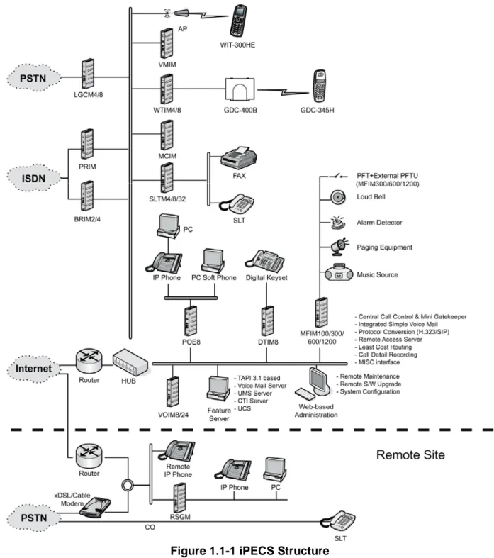
iPECS is LG-Nortel’s Internet Protocol (IP) Enterprise Communications Solution designed to meet the telecommunication needs of the small to medium sized business. iPECS uses advanced packet voice and IP switching technology, which is combined with a rich feature content, to set a new standard in Voice over IP (VoIP) systems.
iPECS consists of a family of intelligent modules, which are interconnected over a 10/100 Base-T Ethernet LAN, easing the installation process and eliminating the need for an expensive back plane. A variety of modules are available including analog and digital network access gateways, which connect to the Public Switched Telephone Network (PSTN), ISDN or public and private VoIP networks. The Ethernet switch (POE8), which provides connection to individual LIP Phones, incorporates circuitry for “power-feed” supporting Power over Ethernet LANs (PoE). LIP Phones provide the user simple access to the many features and functions of the iPECS.
The modules, which make up the iPECS, can be installed in a Main Cabinet. The cabinet can be desk, 19” rack, or wall mounted, as best fits the user needs and equipment room. Each of the system’s modules is powered from a PSU, which converts 100-240 VAC to 48 VDC. In lieu of the cabinet installation, the modules can be shelf (book-end) mounted, in which case, each module is separately powered from an AC/DC adapter, which converts 100-240 VAC to 48 VDC for use by the module.
iPECS supports a variety of LIP Phones; legacy digital terminals (LKD and LDP models), standard VoIP phones (SIP and H.323 V3) and analogue single line devices. With the LIP Phones, commonly used features are activated by selection of a single button. Additionally, most functions can be accessed from any telephone by dialing specific codes. For LIP and digital Phone users, these “dial codes” may be assigned to Flexible buttons for easy access. In addition to the LIP Phones, optional LIP DSS Consoles are available to expand the number of Flexible buttons available to the user.
iPECS provides an environment rich in features beyond today’s traditional circuit switched telephone systems. In addition to a fully featured voice intercom, the iPECS incorporates enhanced messaging, basic Auto Attendant/Voice Mail, Least Cost Routing, and Automatic Call Distribution, as well as Web based Admin, and VoIP network interface. iPECS incorporates an interface to the iPECS Applications Service Provider, a TAPI 3.1 TSP/MSP. The Application Service Provider links the iPECS to advanced Computer-Telephony applications of the iPECS Feature Server. In addition to the iPECS Auto Attendant/Voice Mail and iPECS Unified Messaging applications developed by LG-Nortel, third party TAPI 3.1 application support is provided. Unified Communications Services (UCS) are supported through optional application software providing enhanced communications and presence. An optional Network Management Server (NMS)
infrastructure and ability to easily install or relocate modules and telephones results in significant savings at installation and over the life of the system.
The reliability, extensive feature content, the ability to support present and future applications with the iPECS Feature Server and the capability to use an array of modules and instruments, permit the iPECS to be tailored to meet the short and long term needs of the most demanding customer requirements.
Figure 1.1-1 below is a diagram of the various modules, terminals and applications available with iPECS.
1.2 Hardware Components Chart
Table 1.2-1 provides a description of the hardware components that make-up iPECS. All of the iPECS Modules and terminals are connected over a 10/100 Base-T Ethernet LAN.
Table 1.2-1 iPECS Modules and Terminals
ITEM DESCRIPTION
MFIM100 Multi-Function Interface gateway Module, 100 ports w/VSF ~ 210 min MFIM300 Multi-Function Interface gateway Module, 300 ports w/VSF ~ 210 min MFIM600 Multi-Function Interface gateway Module, 600 ports
1
MFIM1200 Multi-Function Interface gateway Module, 1200 ports 2 PSU Power Supply Unit for Enhanced Main Cabinet, 250W 3 VOIM8 Voice over IP Module, 8-Ch
4 VOIM24 Voice over IP Module, 24-Ch
5 LGCM4 Loop Start CO gateway Module, 4 ports 6 LGCM8 Loop Start CO gateway Module, 8 ports 7 DIDM8 DID gateway Module, 8 ports
8 DTIM8 Digital Terminal Interface gateway Module, 8 ports 9 SLTM4 Single Line Telephone gateway Module, 4 ports 10 SLTM8 Single Line Telephone gateway Module, 8 ports 11 SLTM32 Single Line Telephone gateway Module, 32 ports 12 BRIM2 BRI gateway Module, 2 port ISDN “T” Interface (2B+D) 13 BRIM4 BRI gateway Module, 4 port ISDN “T” Interface (2B+D) 14 PRIM PRI gateway Module, 1 port, 30 channels
15 VMIM Voice Mail Interface Module, 8-ch, 9 hour AA/VM module 16 MCIM Multi-Media Conference Module (up to 32-party voice) 17 WTIM4 Wireless Terminal Interface gateway Module, 4 ports
18 WTIM8 Wireless Terminal Interface gateway Module, 8 ports
19 RSGM Remote Services Gateway Module
20 POE8 Power over Ethernet Switching Hub, 8 ports with Uplink port 21 AC/DC Adapter –G- AC/DC Adapter for modules, (48VDC, 0.83A)
22 AC/DC Adapter –K- AC/DC Adapter for LIP Phones and DSS Console, (48VDC, 0.3A) 23 DHLD Desk mount Holder for module
24 DHE Desk mount Holder Extender, one (1) required for each Module 25 WHLD Wall mount Holder for module
26 MCKTE Main Cabinet Kit Enhanced
28 WBRKE Wall mount Bracket Kit for Enhanced Main Cabinet 29 1U-RMB 1U Rack mount Bracket for gateway Modules 29 LIP-7004N LIP Phone, Basic 4 button no display
38 LIP-8040L LIP Phone, 10 button, 9-line display w/Menu, Soft & Nav. buttons 39 LIP-8048DSS LIP DSS Console with 48 buttons
40 LIP-8012DSS LIP DSS Console with 12 buttons
41 LIP-8012LSS LIP DSS Console with 12 buttons, w/12-line LCD button label 42 LIP-7004WMK Wall Mount Kit for LIP-7004N
43 LIP-7008WMK Wall Mount Kit for 7008D
44 LIP-7024WMK Wall Mount Kit for LIP-7016D, 7024D & 7024LD 45 WIT-300HE iPECS WLAN Phone
46 GDC-400B DECT Base Station 47 GDC-400H DECT Handset
2 Hardware
Description
2.1 iPECS
Modules
2.1.1 MFIMs
(Multi-Function
Interface gateway Module)
The Multi-Function Interface gateway Modules (MFIM100, MFIM300, MFIM600 and MFIM1200), which are the main controller for iPECS and employ the iPECS protocol, extend telephony resources and call processing to the iPECS modules and terminals. Multi-Function Interface gateway Modules incorporate miscellaneous interfaces for Music-On-Hold (MOH), Background Music (BGM), contact monitors for Alarm and Doorbell inputs, Loud Bell Contacts, and Power Fail Transfer (PFT) relays. Also, Multi-Function Interface gateway Modules include battery back-up circuitry using a long-life Lithium battery to maintain the real-time clock and prevent loss of system database during power fail, refer to section 4.5.2.
There are several types of MFIMs as shown in Table 2.1.1-1.
Table 2.1.1-1 MFIMs Comparison Chart
ITEM MFIM100 MFIM300 MFIM600 MFIM1200
System Capacity 100 300 600 1200
CO/IP Lines 42 200 600 1200
Stations 70 300 600 1200
Relay Contacts 2 4 4 4
VSF 210 min 210 min n/a n/a External PFTU No Yes Yes Yes
VoIP Channels 6 6 n/a n/a
USB Host port 1 port 1 port 1 port 1 port
Not all capacities can be simultaneously achieved, for detailed capacity specifications refer to section 3.1.
With the exception of the MFIM600 and MFIM1200, MFIMs incorporate an IP Gateway for access to standards based (SIP and H.323 v3) and iPECS protocol Voice over IP (VoIP) communications networks and a voice storage medium, the VSF. The IP gateway supports up to 6 simultaneous full duplex packet voice channels. Transcoding for major codecs (g.711, g.729a, g.723.1) is provided by on-board DSP circuitry. The VSF is used for the integrated Automated Attendant and Voice Mail services available in the iPECS software. The MFIM100 and MFIM300 have a voice storage capacity of approximately 210 minutes.
MFIMs have a 10/100 Base-T Ethernet interface, the “LAN1” RJ-45 type connector, which is the interface to the iPECS call server features and functions. Each MFIM has a second 10/100 Base-T Ethernet interface “LAN2” RJ-45 type connector. The “LAN2” port is employed for redundant
• RCA jack for one music (audio) source -BGM1-,
• One (1) “LAN1” RJ-45 Female LAN connector with Speed and Link/Activity LEDs,
• One (1) “LAN2” RJ-45 Female LAN connector with Speed and Link/Activity LEDs,
• Four (4)-position DIP-switch for mode selections,
• Ten (10) LEDs,
• Five (5) red LEDs display the operating status of the main processor,
• Five (5) green LEDs display the operating status of MISC functions,
• One (1) DB-9 RS-232 connector and one (1) USB host port,
• Reset Switch.
On the rear panel, each MFIM has:
• Eight (8) RJ-45 female connectors; for Alarm, BGM/MOH and Control Relay inputs, External Page outputs and Power Fail Transfer circuits,
• Ground Lug,
• Fifty (50)-pin back plane connector.
2.1.2 VOIM8 & 24 (Voice Over IP gateway Modules)
The eight (8) and twenty-four (24) channel Voice over IP gateway Module (VOIM8 and VOIM24) perform packet translation between standard H.323 or SIP protocol and the iPECS proprietary protocol. The VOIM8 contains a single processor to support eight (8) VoIP calls. The VOIM24 contains 2 processors to support maximum twenty-four (24) VoIP calls. The main processor manages packet switching and signaling for all VoIP calls. DSPs are employed to support in-band DTMF detection and transcoding between various codec types for each IP channel. The transcoding feature enables users to communicate with each other, when the codec between iPECS and other terminal is different.
The VOIM8 and VOIM24 include a 10/100 Base-T Ethernet interface using an RJ-45 type connector. A second “LAN2” RJ-45 type connector is provided for future use. Both Ethernet ports incorporate auto MDI and MDIX switching feature allowing use of either straight cable and cross cable.
As shown in Figure 2.1.2-1, the front panels of the VOIM8 and 24 have:
• Power jack for the AC/DC adapter; see section 2.1.15 AD/DC adapter –G-,
• Power status LED,
• Normal/Service switch,
• One (1) RJ-45 Female LAN connector for master processor with Speed and Link/Act LEDs,
• One (1) RJ-45 Female LAN connector with Speed and Link/Act LEDs
• Five (5) status LEDs,
• One (1) DB-9 RS-232
connector,
• Reset Switch.
On the rear panel, the VOIM8 and 24 have:
• Ground Lug,
• Fifty (50)-pin back plane connector.
2.1.3 LGCMs (Loop Start CO gateway Module)
2.1.3.1
LGCM4
The four (4)-port Loop Start CO gateway Module (LGCM4) provides four (4) CO/PBX Loop Start Line interfaces. These interfaces support pulse or DTMF dial signals. Each Interface contains ring and loop current detection circuits, speech codec and compression functions and loop signaling circuits. The circuitry and software support tone detection. A Call Metering Unit (CMU4) optional module is needed to use the call metering function. Each CMU4 supports 4 ports and there are three versions, based on protocol CMU4-12PR, CMU4-16, CMU4-50PR. Each version is for different regions as shown below.
• 12PR – Australia, Denmark, Italy, Spain, Sweden
• 16 – Belgium, India, Israel, Norway, South Africa
• 50PR – Australia, India, South Africa, South Korea, United Kingdom
The LGCM4 includes a 10/100 Base-T Ethernet interface as well as packet voice processing functions. The Ethernet port incorporates auto MDI, MDIX switching, therefore, both straight and cross cables can be used.
As shown in Figure 2.1.3.1-1, the front panel of the LGCM4 has:
• Power jack for the AC/DC adapter; see section 2.1.15 AD/DC adapter –G-,
• Power status LED,
• Normal/Service switch – In Service mode, circuits in use are busied as they return to idle,
• RJ-45 Female LAN connector with Speed and Link/Activity LEDs,
• Four (4) LEDs, one for status of each CO line,
• One (1) LED to indicate if a CMU is installed,
• DB-9 RS-232 connector,
• Reset Switch.
On the rear panel, the LGCM4 has:
• Four (4) RJ-45 female connectors
• Ground Lug,
• Fifty (50)-pin back plane connector.
2.1.3.2
LGCM8
The eight (8)-port Loop Start CO gateway Module (LGCM8) provides eight (8) CO/PBX Loop Start Line interfaces. These interfaces support pulse or DTMF dial signals. Each Interface contains ring and loop current detection circuits, speech codec and compression functions, and loop signaling circuits. The circuitry and software support tone detection. Two Call Metering Unit (CMU4) optional modules are needed to use the call metering function. Each CMU4 supports four (4) ports and there are three versions based on protocol 12PR, 16, CMU4-50PR. Each version is for different regions as shown below.
• 12PR – Australia, Denmark, Italy, Spain, Sweden
• 16 – Belgium, India, Israel, Norway, South Africa
• 50PR – Australia, India, South Africa, South Korea, United Kingdom
The LGCM8 includes a 10/100 Base-T Ethernet interface as well as packet voice processing functions. The Ethernet port incorporates auto MDI, MDIX switching, therefore, both straight and cross cables can be used.
As shown in Figure 2.1.3.2-1, the front panel of the LGCM8 has:
• Power jack for the AC/DC adapter; see section 2.1.15 AD/DC adapter –G-,
• Power status LED,
• Normal/Service switch – In Service mode, circuits in use are busied as they return to idle,
• RJ-45 Female LAN connector with Speed and Link/Activity LEDs,
• Eight (8) LEDs, one for status of each CO line,
• Two (2) LEDs, one to indicate installation of each CMU4,
• DB-9 RS-232 connector,
• Reset Switch.
On the rear panel, the LGCM8 has:
• Eight (8) RJ-45 female connectors,
• Ground Lug,
• Fifty (50)-pin back plane connector.
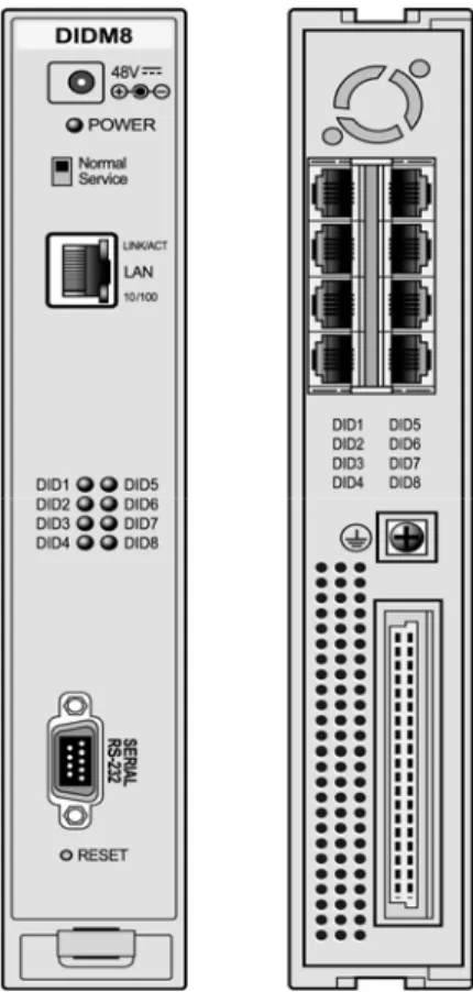
2.1.4 DIDM8 (DID gateway Module)
The eight (8)-port Direct-In-Dial gateway Module (DIDM8) provides interfaces to Direct-In-Dial Lines, supporting wink or immediate start signaling. These special PSTN lines are incoming only and send the last few digits of the dialed number to the DIDM8 identifying a particular extension/user in the system.
The DIDM8 provides interface circuitry for eight (8) DID Lines. Each interface is equipped with appropriate speech codec and compression functions, pulse and DTMF dial signal detection. The DIDM8 includes a 10/100 Base-T Ethernet interface as well as packet voice processing functions. The Ethernet port incorporates auto MDI, MDIX switching, therefore, both straight and cross cables can be used.
As shown in Figure 2.1.4-1, the front panel of the DIDM8 has:
• Power jack for the AC/DC adapter ;see section 2.1.15 AD/DC adapter –G-,
• Power status LED,
• Normal/Service switch – In Service mode, circuits in use are busied as they return to idle -,
• RJ-45 Female LAN connector with Speed and Link/Activity LEDs,
• Eight (8) DID LEDs, one for status of each DID Line,
• DB-9 RS-232 connector,
• Reset Switch.
On the rear panel, the DIDM8 has:
• Eight (8) RJ-45 female connectors,
• Ground Lug,
• Fifty (50)-pin back plane connector.
2.1.5 DTIM8 (Digital Terminal Interface gateway Module)
The eight (8)-channel Digital Terminal Interface gateway Module supports 8 digital keysets (LKD and LDP models). Keysets have access to all the resources of the iPECS as well as keyset functionality and simple one-button feature access. The DTIM8 contains a processor for IP to TDM and signaling conversion as well as DSP circuitry to provide transcoding for each channel.
Digital keysets can be connected up to 300 meters from the DTIM8 gateway using 24 AWG twisted pair cabling.
The DTIM8 includes a 10/100 Base-T Ethernet interface as well as packet voice processing functions. The Ethernet port incorporates auto MDI, MDIX switching, therefore, both straight and cross cables can be used.
As shown in Figure 2.1.5-1, the front panel of the DTIM8 has:
• Power jack for the AC/DC adapter; see section 2.1.15 AD/DC adapter –G-,
• Power status LED,
• Normal/Service switch – In Service mode, circuits in use are busied as they return to idle,
• RJ-45 Female LAN connector with Speed and Link/Activity LEDs,
• Eight (8) DKTU status LEDs, one for status of each DTIM channel,
• DB-9 RS-232 connector,
• Reset Switch.
On the rear panel, the DTIM8 has:
• Eight (8) RJ-45 female connectors,
• Ground Lug,
• Fifty (50)-pin back plane connector.
2.1.6 SLTMs (Single Line Telephone gateway Module)
2.1.6.1
SLTM4
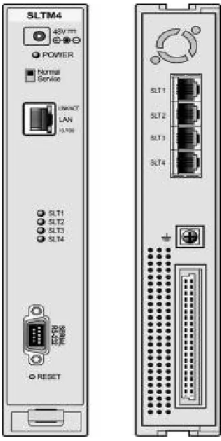
The four (4)-port Single Line Telephone Module (SLTM4) allows standard analog Single Line Telephone (SLT) devices access to CO Lines, other stations, and most features of the system through the use of “dial codes”. The SLTM4 provides interface circuitry for four (4) SLTs. Each interface is equipped with appropriate speech codec and compression functions, 48 volt DC feed circuit, pulse and DTMF dial signal detection. A ring generator and message wait source are integrated in the SLTM4. The SLTM4 supports T.38 protocol for Fax over IP.
The SLTM4 allows Single Line Telephones to be connected up to 4 Kilometers (13,000 feet) from the gateway using 24 AWG wire.
The SLTM4 includes a 10/100 Base-T Ethernet interface as well as packet voice processing functions. The Ethernet port incorporates auto MDI, MDIX switching, therefore, both straight and cross cables can be used.
As shown in Figure 2.1.6.1-1, the front panel of the SLTM4 has:
• Power jack for the AC/DC adapter; see section 2.1.15 AD/DC adapter –G-,
• Power status LED,
• Normal/Service switch – In Service mode, circuits in use are busied as they return to idle,
• RJ-45 Female LAN connector with Speed and Link/Activity LEDs,
• Four (4) SLT LEDs, one for status of each SLT,
• DB-9 RS-232 connector,
• Reset Switch.
On the rear panel, the SLTM4 has:
• Four (4) RJ-45 female connectors,
• Ground Lug,
• Fifty (50)-pin back plane connector.
2.1.6.2
SLTM8
The eight (8)-port Single Line Telephone Module (SLTM8) allows standard analog Single Line Telephone (SLT) devices access to CO Lines, other stations, and most features of the system through the use of “dial codes”. The SLTM8 provides interface circuitry for eight (8) SLTs. Each interface is equipped with appropriate speech codec and compression functions, 48 volt DC feed circuit, pulse and DTMF dial signal detection. A ring generator and message wait source are integrated in the SLTM8. The SLTM8 supports T.38 protocol for Fax over IP.
The SLTM8 allows Single Line Telephones to be connected up to 4 Kilometers (13,000 feet) from the gateway using 24 AWG wire.
The SLTM8 includes a 10/100 Base-T Ethernet interface as well as packet voice processing functions. The Ethernet port incorporates auto MDI, MDIX switching, therefore, both straight and cross cables can be used.
As shown in Figure 2.1.6.2-1, the front panel of the SLTM8 has:
• Power jack for the AC/DC adapter; see section 2.1.15 AD/DC adapter –G-,
• Power status LED,
• Normal/Service switch – In Service mode, circuits in use are busied as they return to idle,
• RJ-45 Female LAN connector with Speed and Link/Activity LEDs,
• Eight (8) SLT LEDs, one for status of each SLT,
• DB-9 RS-232 connector,
• Reset Switch.
On the rear panel, the SLTM8 has:
• Eight (8) RJ-45 female connectors,
• Ground Lug,
• Fifty (50)-pin back plane connector.
2.1.6.3
SLTM32
The thirty-two (32)-port Single Line Telephone Module (SLTM32) allows standard analog Single Line Telephone (SLT) devices access to CO Lines, other stations, and most features of the system through the use of “dial codes”. The SLTM32 provides interface circuitry for thirty-two (32) SLTs. Each interface supports appropriate speech codec and compression functions, 36 volt DC feed circuit; pulse and DTMF dial signal detection. A ring generator and message wait circuitry are integrated in the SLTM32. The SLTM32 supports T.38 protocol for Fax over IP.
The SLTM32 allows Single Line Telephones to be connected up to 3 Kilometers (9,800 feet) from the gateway using 24 AWG wire.
The SLTM32 includes a 10/100 Base-T Ethernet interface as well as packet voice processing functions. The Ethernet port incorporates auto MDI, MDIX switching, therefore, both straight and cross cables can be used.
As shown in Figure 2.1.6.3-1, the front panel of the SLTM32 has:
• Power status LED,
• Fan status LED,
• Normal/Service switch – In Service mode, circuits in use are busied as they return to idle,
• RJ-45 Female LAN connector with Speed and Link/Activity LEDs,
• Thirty-two (32) SLT LEDs, one for status of each SLT,
• DB-9 RS-232 connector,
• Reset Switch.
On the rear panel, the SLTM32 has:
• Two (2) 25-pair RJ-21x connectors,
• Ground Lug,
• AC input connector.
2.1.7 BRIMs (BRI gateway Module)
2.1.7.1
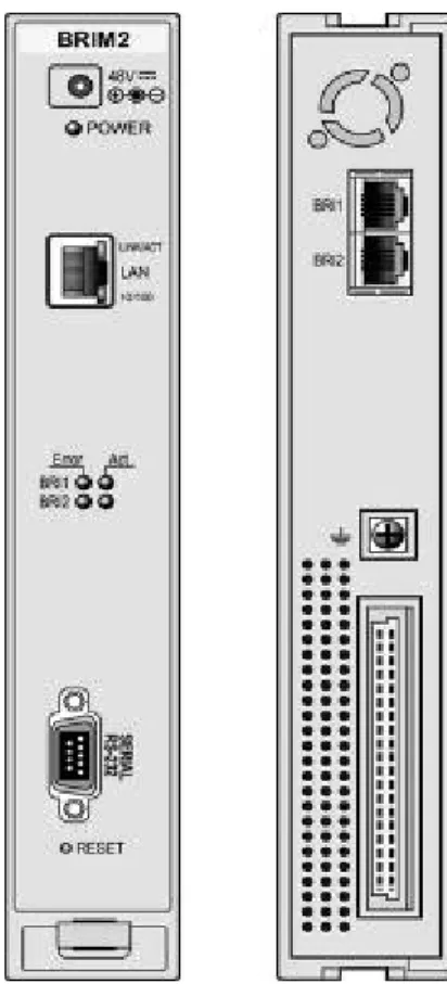
BRIM2
The Basic Rate Interface gateway Module (BRIM2) has two (2) ISDN Basic Rate Interface ports (2B+D). This Module supports the ‘T’ interface as described by ETSI 300.012 based on the ITU-T Recommendations I.430, and can be installed in the ITU-TE (Terminal Equipment) mode.
The BRIM2 includes a 10/100 Base-T Ethernet interface as well as packet voice processing functions. The Ethernet port incorporates auto MDI, MDIX switching, therefore, both straight and cross cables can be used.
As shown in Figure 2.1.7.1-1, the front panel of the BRIM2 has:
• Power jack for the AC/DC adapter; see section 2.1.15 AD/DC adapter –G-,
• Power status LED,
• Normal/Service switch – In Service mode, circuits in use are busied as they return to idle,
• RJ-45 Female LAN connector with Speed and Link/Activity LEDs,
• Four (4) status LEDs -two (2) for each BRI Line,
• DB-9 RS-232 connector,
• Reset Switch.
On the rear panel, the BRIM2 has:
• Two (2) RJ-45 female connectors, one for each BRI Line,
• Ground Lug,
• Fifty (50) pin-back plane connector.
2.1.7.2
BRIM4
The Basic Rate Interface gateway Module (BRIM4) has four (4) ISDN Basic Rate Interface ports (2B+D). The BRIM4 supports the ‘T interface’ as described by ETSI 300.012 based on the ITU-T Recommendations I.430, and can be installed in the TE (Terminal Equipment) mode. The BRIM4 includes DSP circuitry for transcoding between various audio codecs.
The BRIM4 includes a 10/100 Base-T Ethernet interface as well as packet voice processing functions. The Ethernet port incorporates auto MDI, MDIX switching, therefore, both straight and cross cables can be used.
As shown in Figure 2.1.7.2-1, the front panel of the BRIM4 has:
• Power jack for the AC/DC adapter; see section 2.1.15 AD/DC adapter –G-,
• Power status LED,
• Normal/Service switch – In Service mode, circuits in use are busied as they return to idle,
• One (1) RJ-45 Female LAN connector with Speed and Link/Activity LEDs,
• Eight (8) LEDs, two (2) for each BRI Line,
• DB-9 RS-232 connector,
• Reset Switch.
On the rear panel, the BRIM4 has:
• Four (4) RJ-45 female connectors,
• Ground Lug,
• Fifty (50)-pin back plane connector.
2.1.8 PRIM (PRI gateway Module)
The PRIM module provides one (1) PRI interface. This interface supports 30 PCM bearer and 2 signaling channels for ISDN PRI.
The PRIM includes a 10/100 Base-T Ethernet interface as well as packet voice processing functions. The Ethernet port incorporates auto MDI, MDIX switching, therefore, both straight and cross cables can be used.
As shown in Figure 2.1.8-1, the front panel of the PRIM has:
• Power jack for the AC/DC adapter; see section 2.1.15 AD/DC adapter –G-,
• Power status LED,
• Normal/Service switch – In Service mode, circuits in use are busy as they return to idle,
• RJ-45 Female LAN connector with Speed and Link/Activity LEDs,
• Five (5) LEDs,
• DB-9 RS-232 connector,
• Reset Switch.
On the rear panel, the PRIM has:
• One (1) RJ-45 female connector,
• Ground Lug,
• Fifty (50)-pin back plane connector.
2.1.9 VMIM
(Voice
Mail Interface Module)
The VMIM (Voice Mail Interface Module) provides mid-range Auto Attendant/Voice Mail services for the iPECS, primarily intended to support the MFIM600 but can be employed with any MFIM. The VMIM contains a processor and DSP circuitry to support 8 simultaneous channels and memory to support 9 hours of voice storage capacity. To provide additional channels and/or storage capacity, up to three (3) VMIMs may be installed in systems with an MFIM600 for a maximum capacity of 24 channels and 27 hours of storage. For other systems a maximum of two (2) VMIMs can be supported for a maximum capacity of 16 channels and 18 hours of storage. In addition to Auto Attendant and Voice Mail functions, the VMIM also provides ACD announcements as well as Pre-defined and Custom Message Voice announcements. The VMIM can support various codecs including g.711, g.729a, and g.723.1.
The VMIM includes a 10/100 Base-T Ethernet interface as well as packet voice processing functions. The Ethernet port incorporates auto MDI, MDIX switching, therefore, both straight and cross cables can be used.
As shown in Figure 2.1.9-1, the front panel of the VMIM has:
• Power jack for the AC/DC adapter; see section 2.1.15 AD/DC adapter –G-,
• Power status LED,
• Normal/Service switch – In Service mode, circuits in use are busy as they return to idle,
• RJ-45 Female LAN connector with Speed and Link/Activity LEDs,
• Four (4) Status LEDs,
• One (1) USB Host port connector,
• DB-9 RS-232 connector,
• Reset Switch.
On the rear panel, the VMIM has:
• Ground Lug,
• Fifty (50)-pin back plane connector.
2.1.10 MCIM (Multi-Media Conference Interface gateway Module)
The Multi-Media Conference Interface gateway Module (MCIM) permits users to establish multi-party voice conferences with up to 32 simultaneous parties using the g.711 or g.729 codec and 24 parties with the g.723 codec. The MCIM contains a control processor as well as DSP circuitry to support conferences.
The MCIM includes a 10/100 Base-T Ethernet interface as well as packet voice processing functions. The Ethernet port incorporates auto MDI, MDIX switching, therefore, both straight and cross cables can be used.
As shown in Figure 2.1.10-1, the front panel of the MCIM has:
• Power jack for the AC/DC adapter; see section 2.1.15 AD/DC adapter –G-,
• Power status LED,
• Normal/Service switch – In Service mode, circuits in use are busy as they return to idle,
• RJ-45 Female LAN connector with Speed and Link/Activity LEDs,
• Four (4) Status LEDs,
• DB-9 RS-232 connector,
• Reset Switch.
On the rear panel, the MCIM has:
• Ground Lug,
• Fifty (50)-pin back plane connector.
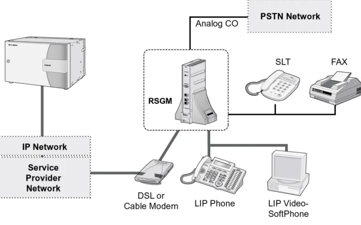
2.1.11 RSGM (Remote Services Gateway Module)
The Remote Services Gateway Module (RSGM) transparently extends iPECS services to users and interfaces over broadband IP networks. Remote Services are implemented with the iPECS Remote Services Application Server employing the system’s VoIP channels to communicate with remote LIP Phones and RSGMs. Typical remote configurations are shown in Figure 2.1.11-1. Note that the Remote Application can service multiple LIP Phones and RSGMs separately and simultaneously.
Figure 2.1.11-1 RSGM Connection
The RSGM provides following resources.
• One (1) WAN connection port (RJ-45: 10/100 Ethernet port) – Auto MDI, MDIX switching feature,
• One (1) PC port (RJ-45: 10/100 Ethernet port),
• One (1) LIP Phone port (RJ-45: 10/100 Ethernet port) w/PoE support,
• One (1) analog CO port (RJ-11),
• One (1) analog SLT port (RJ-11),
• One (1) BGM port,
• One (1) Alarm/Doorbell contact monitor,
• Two (2) dry relay contacts.
The RSGM includes 10/100 Base-T Ethernet interfaces as well as packet voice processing functions. The WAN connection Ethernet port has auto MDI, MDIX switching, therefore, both straight and cross cables can be used.
As shown in Figure 2.1.11-2, the front panel of the RSGM has:
• Power status LED,
• RCA jack for external music (audio) source -BGM-,
• Eight (8) LEDs,
• RJ-45 Female LAN connector with Speed and Link/Activity LEDs for WAN connection,
• RJ-45 Female LAN connector with Speed and Link/Activity LEDs for PC connection,
• RJ-45 Female LAN connector with Speed and Link/Activity LEDs for IP phone connection,
• LED indicator to display IP phone power feeding status. On the rear panel, the RSGM has:
• One (1) RJ-11 female connector for analog CO Line,
• One (1) RJ-11 female connector for analog SLT,
• One (1) RJ-11 female connector for alarm/door bell input and dry relay contact #2,
• One (1) RJ-11 female connector for external BGM and dry relay contact #1,
• Four (4)-position DIP-switch for mode selections,
• One (1) position DIP-switch for IP phone power feeding selection,
• DB-9 RS-232 connector,
• Reset Switch,
• Power jack for the AC/DC adapter supplied; see section 2.1.15 AD/DC adapter –G-,
• Ground Lug.
2.1.12 POE8 (Power Over Ethernet switching hub)
The Power over Ethernet Switching Module (POE8) has eight (8) LAN ports and an UPLINK LAN port, all of which employ Ethernet switching. All ports support Auto-sense 10/100Mbps, half/full duplex mode and auto MDI/MDIX function. Therefore a straight or cross RJ-45 cable can be used for connection between two Ethernet ports. The POE8 is a standard nine (9) port Ethernet switch, which switches packets between two specified ports. Unlike a repeater that repeats each packet to all ports, using the POE8 minimizes traffic over each port as well as the overall LAN environment. The eight (8) LAN ports of the POE8 are equipped with circuitry to provide power (48 VDC) to the LIP Phone or LIP-7000 series console through the LAN cable. The POE8 supplies power automatically to terminals in accordance with the IEEE 802.3af PD (Powered Device) specification. LEDs are provided on the front panel to display the power feed status of each port. Note the UPLINK LAN port is not equipped with the power feed circuitry.
As shown in Figure 2.1.12-1, the front panel of the POE8 has:
• Power jack for the AC/DC adapter; see section 2.1.15 AD/DC adapter –G-,
• Power status LED,
• Eight (8)-port “PORT PWR STATUS” LEDs,
• One (1) RJ-45 Female “UPLINK” LAN connector with Speed and Link/Activity LEDs,
• Eight (8) RJ-45 Female LAN connectors with Speed and Link/Activity LEDs, one per port.
On the rear panel, the POE8 has:
• DB-9 RS-232 Serial port connector,
• Ground Lug,
• Fifty (50)-pin back plane connector.
2.1.13 WTIM (Wireless Telephone Interface Module)
2.1.13.1
WTIM4
The four (4)-channel Wireless Terminal Interface gateway Module (WTIM4) provides four (4) interfaces for GDC-400B, which is a DECT base station classified as the Remote Fixed Part (RFP) in the DECT specification. DECT handsets can be used if the GDC-400B is connected to a WTIM4 and the proper attendant programming is completed. The WTIM4 contains a processor for IP to TDM voice and signaling conversion and DSP circuitry to provide transcoding for each channel. The GDC-400B can be connected to the WTIM4 up to 600 meters from the gateway using 24 AWG twisted pair cabling.
The WTIM4 includes a 10/100 Base-T Ethernet interface as well as packet voice processing functions. The Ethernet port incorporates auto MDI, MDIX switching, therefore, both straight and cross cables can be used.
As shown in Figure 2.1.13.1-1, the front panel of the WTIM4 has:
• Power jack for the AC/DC adapter; see section 2.1.15 AD/DC adapter –G-,
• Power status LED,
• Normal/Service switch – In Service mode, circuits in use are busied as they return to idle,
• RJ-45 Female LAN connector with Speed and Link/Activity LEDs,
• Four position Mode switch,
• Eight (8) WTIM4 status LEDs,
• Two RJ-45 Sync connectors to link WTIMs
• DB-9 RS-232 connector,
• Reset Switch.
On the rear panel, the WTIM4 has:
• Eight (4) RJ-45 female connectors,
• Ground Lug,
• Fifty (50)-pin back plane connector,
2.1.13.2
WTIM8
The eight (8)-channel Wireless Terminal Interface gateway Module (WTIM8) provides eight (8) interfaces for the GDC-400B, which is a DECT base station classified as the Remote Fixed Part (RFP) in the DECT specification. DECT handsets can be used if the GDC-400B is connected to the WTIM8 and the proper attendant programming is completed. The WTIM8 contains a processor for IP to TDM and signaling conversion and DSP circuitry to provide trans-coding for each channel. The GDC-400B can be connected to the WTIM8 up to 600 meters from the gateway using 24 AWG twisted pair cabling.
The WTIM8 includes a 10/100 Base-T Ethernet interface as well as packet voice processing functions. The Ethernet port incorporates auto MDI, MDIX switching, therefore, both straight and cross cables can be used.
As shown in Figure 2.1.13.2-1, the front panel of the WTIM8 has:
• Power jack for the AC/DC adapter; see section 2.1.15 AD/DC adapter –G-,
• Power status LED,
• Normal/Service switch – In Service mode, circuits in use are busied as they return to idle,
• RJ-45 Female LAN connector with Speed and Link/Activity LEDs,
• Four position Mode switch,
• Eight (8) WTIM8 status LEDs,
• Two RJ-45 Sync connectors to link WTIMs
• DB-9 RS-232 connector,
• Reset Switch.
On the rear panel, the WTIM8 has:
• Eight (8) RJ-45 female connectors,
• Ground Lug,
• Fifty (50)-pin back plane connector,
2.1.14 PSU (Power Supply Unit)
The Power Supply Unit (PSU) converts 100-240 VAC @ 50/60 Hz to -48V and 5V DC. The DC voltages are connected to the back plane for distribution to modules installed in the Enhanced Main Cabinet. Power is connected via the back plane connector on the PSU and individual modules.
In most configurations, the PSU is capable of supplying power to a full cabinet of nine (9) modules. However, current draw for the different modules varies greatly; PSTN, ISDN and some other modules require about 5 watts each while a POE8 driving power to 8 phones requires 40 watts. Designing a power source to deliver the maximum power to nine POE8 modules would create cost penalty for most configurations. A simple rule of thumb is to limit the number the number of WTIM8, WTIM8 and POE8 modules to 5 per cabinet. To calculate the precise current draw of any cabinet configuration, use the Power draw chart in section 3.1.3.2. The total current required must be less than the PSU capacity, 5.3 amps. If more than the PSU capacity, reconfigure the cabinet modules or install some of the modules in a second cabinet with a separate PSU.
The PSU includes a DB9 connector for RS-232 communication with gateway modules for alarm notifications.
As shown in Figure 2.1.14-1, the front panel of the PSU has:
• Six (6) Status LEDs,
• Alarm Switch – to activate local audio alarm via the buzzer,
• Buzzer for local audio indication of alarm condition,
• DB-9 RS-232 connector,
• Power Switch,
• AC Power Input,
• Fuse.
On the rear panel, the PSU has:
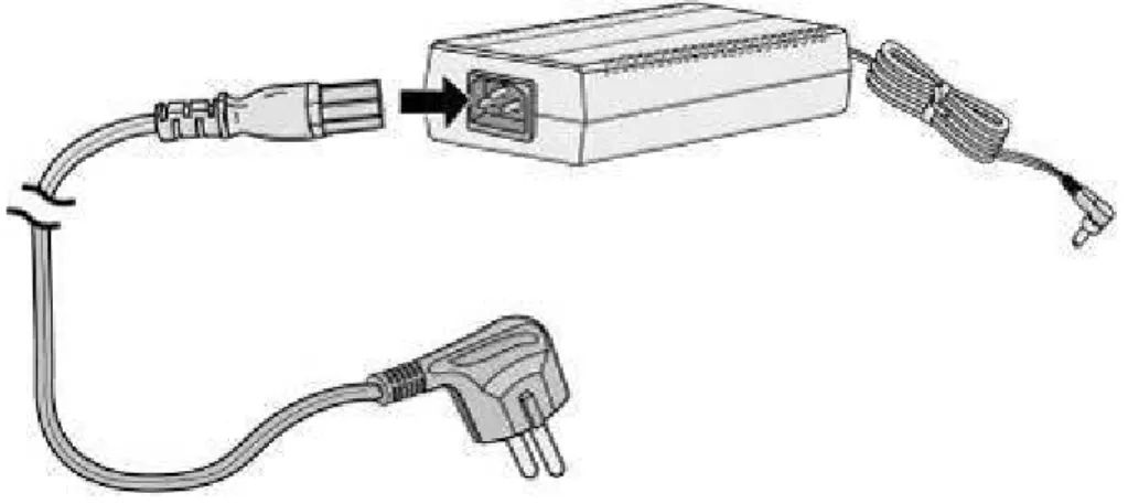
2.1.15 AD/DC adapter –G-
An optional AC/DC adapter is available to power a module when the PSU is not employed. The adapter is supplied with a two (2) meter, six (6) foot, AC cord terminated with the nationally relevant AC blade type. The adapter supports AC input power systems with rated voltage range of 100-240 VAC @ 50/60 Hz. The adapter provides 48 VDC, 0.8 amps. The DC output connector is cabled to the adapter with a two (2) meter, six (6) foot, cable.
Figure 2.1.15-1 shows the AC/DC Adapter for the iPECS Modules.
2.2 LIP Phones & Terminals
iPECS will work with a number of telephone types including standard SLTs, VoIP phones (SIP or H.323 v3), the LIP Phones. The LIP Phones are available in several configurations as shown in the Table 2.2-1.
Table 2.2-1 LIP Phones
MODEL DESCRIPTION
LIP-7004N Basic LIP Phone, 4 Flex buttons, no display LIP-7008D LIP Phone w/8 Flex buttons and 2 line display
LIP-7016D LIP Phone w/16 Flex buttons, 3-line display, Navigation and soft-keys LIP-7024D LIP Phone w/24 Flex buttons, 3-line display, Navigation and soft-keys
LIP-7024LD LIP Phone w/24 Flex buttons, Multi-line large display, Navigation and soft-keys LIP-7048DSS LIP DSS Console with 48 Flex buttons,
WIT300HE iPECS WLAN Wireless Phone
LIP-8004D LIP Phone, 4 button and 1-line display, LAN 1 port
LIP-8012D LIP Phone, 12 button, 3-line display w/Menu, Soft & Nav. buttons LIP-8024D LIP Phone, 24 button, 4-line display w/Menu, Soft & Nav. buttons LIP-8040L LIP Phone, 10 button, 9-line display w/Menu, Soft & Nav. buttons LIP-8048DSS LIP DSS Console with 48 buttons
LIP-8012DSS LIP DSS Console with 12 buttons
LIP-8012LSS LIP DSS Console with 12 buttons, 12-line display z Note: All LIP Phones are compliant to IEEE 802.3af standards.
2.2.1 LIP-8000 Series Phones
The LIP-8000 series phones are available in four models as well as three models of matching DSS/BLF Consoles. The models include:
• LIP-8004D, 4-button 1 line display
• LIP-8012D, 12-button 3 line display
• LIP-8024D, 24-button 4 line display
• LIP-8040L, 10-button large display
• LIP-8048DSS, 48-button DSS/BLF Console
• LIP-8012DSS, 12-button DSS/BLF Console
• LIP-8012LSS, 12-button 12 line LCD DSS/BLF Console
Each of the above models is shown in Figure 2.2.1-1 to Figure 2.2.1-7. The LIP-8004D has a single LAN port for connection to the external 10/100 Base-T LAN. The other phones in the LIP-8000 series have two (2) LAN ports and thus two (2) RJ-45 connectors. One port is for connection to the LAN, the other can be connected to the desktop data device (PC) or other LAN interface
associated LIP-8000 phone. Up to three (3) 48 button consoles may be connected in a daisy chain to one LIP-8000 phone. The LIP8048DSS is powered from an AC/DC adapter only.
Each LIP-8000 series IP phone has a standard 12-button dial-pad, color coordinated handset, an array of 4 (four) to twenty-four (24) “Flexible buttons”, and fixed feature access buttons. All of the Flexible and most Fixed buttons, incorporate a long-life, super-bright LED to indicate the circuit or feature status.
The fixed feature buttons for each model include the following: LIP-8004D DND Speed Volume Control Trans/PGM Hold/Save Call Back
OHD (On-Hook Dial)
LIP-8012D, LIP-8024D & LIP-8040L
Navigation Menu DND Headset Volume Control Message Trans/PGM Hold/Save Mute Speaker
In addition, the LIP-8012D, 8024D and 8040L include 3 soft buttons. The function of these buttons is interactive and shown in the lower line of the LCD. These models also incorporate a full duplex speakerphone.
The LIP-8000 series phones include a Liquid Crystal Display (LCD). The LIP-8004 has a single line 24-character display; the LIP-8012 and LIP8024D have graphic displays that show three (3) lines with up to 24-characters per line. The lower line is used to display the interactive function of the three soft buttons. The LIP-8040L has a large graphic display that displays the function of the ten flexible buttons and a line to display the function of the three interactive soft buttons.
The LIP-8000 series phone circuitry includes Digital Signal Processing to implement packet voice encoding and decoding, and echo cancellation as well as tone generation and speakerphone operation. Note the LIP-8804D does not include speakerphone operation. The Volume controls, which consist of separate volume up/down buttons, adjusts the level of the handset receiver and speaker as well as the headset receiver, when used.
2.2.3, or powered over the LAN with the POE8 or other 802.3af compliant Ethernet switch. If both the AC/DC Adapter and powered LAN port are connected to the LIP-8000 terminal, the Adapter will provide the required power.
The LIP-8000 series phones incorporate wall mounting in the base of the phone, no additional hardware is required. Note; the matching DSS Console is also wall-mountable.
The DSS Consoles are provided in three models. The LIP-8048DSS has 48 flexible buttons with LED status indicators. The LIP-8012DSS has 12 flexible buttons with LED status indicators. The LIP-8012LSS has 12 flexible buttons and an LCD. The LCD displays the designation and status for each button with up to 20 characters.
Figure 2.2.1-3 LIP-8024D
Figure 2.2.1-5 LIP-8012DSS
2.2.2 LIP-7000 Series Phones
The LIP-7000 series IP phones are available in 5 models as well as a matching DSS/BLF Console. Models available include:
• LIP-7004N, 4-button non-display
• LIP-7008D, 8-button 2-line display
• LIP-7016D, 16-button 3-line display
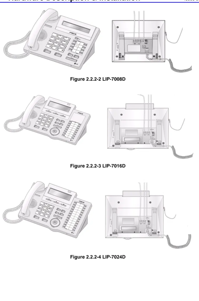
• LIP-7024D, 24-button 3-line display
• LIP-7024LD, 24-button large display
• LIP-7048DSS, 48-button DSS/BLF Console.
Each of the above models and Wall Mount kits are shown in Figure 2.2.2-1 to Figure 2.2.2-8. The LIP-7004N and 7008D have a single LAN port for connection to the external 10/100 Base-T LAN. The LIP-7016D, 7024D and 7024LD models have two (2) LAN ports and thus two (2) RJ-45 connectors. One port is for connection to the LAN, the other can be connected to the desktop data device (PC) or other LAN interface terminal. The ports are connected to an intelligent 10/100Base-T switch, which gives LAN access to the data device while giving priority to voice packets.
The LIP-7048DSS Console, which is used to expand the number of Flexible buttons available to a user by 48 buttons, has two (2) LAN ports. When the console is locally powered with the AC/DC Adapter, the LIP-7048DSS Console can be connected to the PC LAN port of the LIP-7016D, 7024D or 7024LD.
Each LIP-7000 series phone has a standard 12-button dial-pad, color coordinated handset, an array of 4 (four) to twenty-four (24) “Flexible buttons”, and fixed feature access buttons. All of the Flexible and most Fixed buttons, incorporate a long-life, super-bright LED to indicate the circuit or feature status.
The fixed feature buttons for each model include the following: LIP-7004N
OHD (Off-Hook Dial) Hold/Save
Volume Control
Speed (preprogrammed Flex button) Trans/gm (preprogrammed Flex button)
LIP-7008D Speaker (Speakerphone) Hold/Save Volume Control Speed Trans/Pgm
Dnd (preprogrammed Flex button) Call Back (preprogrammed Flex button)
LIP-7016D, 7024D, & 7024LD
Hold/Save Volume Control
Speed Trans/Pgm Dnd Call Back
Navigation buttons
In addition, the LIP-7016, 7024D and 7024LD include 3 Soft buttons. The function of these buttons is interactive and shown in the lower line of the LCD.
The LIP-7008D includes a 2-line, 48-character (24 characters per line) Liquid Crystal Display (LCD). The LCD provides an alphanumeric display to assist the user in operation of features. In the idle mode, the display will show the station name or number on the top line and the time and date on the 2nd line. The LCD is employed to support features such as Dial-By-Name (Directory Dial) using the Volume control to scroll through name displays to find a telephone number in the directory.
The LIP-7000 series IP phone circuitry includes Digital Signal Processing to implement packet voice encoding and decoding, and echo cancellation as well as tone generation and speakerphone operation. The Volume control, which consists of a single volume up/down rocker button, adjusts the level of the handset receiver, speaker as well as the headset receiver, when used.
The LIP-7000 series IP phone may be powered locally with the AC/DC Adapter, reference section 2.2.3, or powered over the LAN with the POE8 or other 802.3af compliant Ethernet switch. If both the AC/DC Adapter and powered LAN port are connected to the LIP-7000 terminal, the Adapter will provide the required power.
Using the appropriate Wall Mount Kit, the LIP-7000 terminal can be mounted on a wall. Two handset hooks, which are used to keep the handset in-place, are molded as part of the Wall Mount bracket. One hook must be removed from the bracket and inserted in the slot just below the hook-switch to hold the handset when wall mounted. Note; the matching Console is not wall-mountable.
Figure 2.2.2-2 LIP-7008D
Figure 2.2.2-3 LIP-7016D
Figure 2.2.2-5 LIP-7024LD
Figure 2.2.2-6 LIP 7004WMB, Wall Mount Bracket
2.2.3 AC/DC Adapter –K- for LIP-Phones & Console
When an LIP-7000 or LIP-8000 series terminal is to be powered from local AC (not provided power over the LAN), a separate AC/DC adapter must be used for power. The adapter is supplied with a two (2) meter, six (6) foot, AC cord terminated with the nationally relevant AC blade type. The adapter supports AC input power systems with rated voltage range of 100-240 VAC @ 50/60 Hz. The adapter provides 48 VDC at 0.3 amps. The DC output connector is cabled to the adapter with a two (2) meter, six (6) foot, cable.
Figure 2.2.3-1 shows the AC/DC Adapter-K.
Figure 2.2.3-1 AC/DC Adapter –K-
2.3 Module Mounting Hardware
Most iPECS modules except for the SLTM32 and PSU can be installed in several different manners:
• Desk mounted using the Desk Mount Holder,
• Wall mounted individually using the Wall Mount Holder,
• 19” rack mounted individually using the 1U-Rack Mount Bracket, or
• Cabinet installed using the Enhanced Main Cabinet, which can be 19” rack, Desk or Wall mounted.
The SLTM32 is intended for 19’ rack mount only and the PSU is intended for cabinet installation only.
The following paragraphs describe the mounting hardware for each of the modules and cabinet mounting options.
2.3.1 DHLD (Desk Mount Holder) / DHE (Desk Mount Holder Extender)
The DHLD (Module Desk Mount Holder) consists of a pair of “book-ends” and DHE (Desk Mount Holder Extender). One Extender is installed between the bookends for each module, and the modules mounted between the bookends. The DHLD and DHE are shown in Figure 2.3.1-1.
Figure 2.3.1-1 DHLD & DHE
2.3.2 WHLD (Wall Mount Holder)
iPECS modules can be individually wall mounted in the WHLD (module Wall Mount Holder), shown in Figure 2.3.2-1. The WHLD provides wall mounting for a single module.
2.3.3 1U-RMB (1U Rack Mount Bracket)
iPECS modules can be individually 19” rack mounted in the 1U-RMB (Rack Mount Bracket), shown in Figure 2.3.3-1. The 1U-RMB provides 19” rack mounting for a single module.
Figure 2.3.3-1 1U RMB
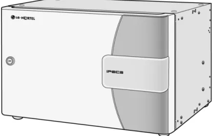
2.3.4 MCKTE (Main Cabinet Kit Enhanced)
The Enhanced Main Cabinet Kit has 10 slots for iPECS modules and PSU. Slot 10 is only for the PSU; slot 9 is for iPECS modules or a PSU when redundant power is required. The remaining slots may be used for any combination of iPECS modules. On the left side, the front cover of the cabinet has a push button for installing and removing the cover and incorporates a key lock, which can be locked to minimize unauthorized access. The cabinet is shown in Figure 2.3.4-1.
Figure 2.3.4-1 Main Cabinet
Available mounting hardware allows the cabinet to be 19” rack mounted, desk mounted, or wall mounted. In the Wall mount installation, the cabinet is connected to the Wall Mount using a hinge wall bracket allowing access to the back plane connectors.
For information on previous versions of the Main Cabinet, please refer to the appropriate previous issue of this manual.
The 19” Rack, Desk and Wall Mount hardware are shown in Figure 2.3.4-2, Figure 2.3.4-3, and Figure 2.3.4-4 below respectively.
2.4 Software Components
iPECS software comes pre-loaded in the various system modules. In addition, application and services software have been developed to expand and enhance iPECS functionality. Applications and Services offered include:
• iPECS Phontage PC SoftPhone • iPECS Phontage PDA SoftPhone • iPECS TSP/MSP - TAPI 3.1
• iPECS Auto Attendant, Voice Mail • iPECS Unified Messaging Services • iPECS ez-Attendant
• iPECS Networking
• iPECS UCS (Unified Communications Services) • iPECS NMS (Network Management Services) • iPECS AIM (Advanced Integration Messaging)
These software packages are documented in other manuals. Contact your local LG-Nortel representative for a list of other documents available for iPECS.
3 SYSTEM
SPECIFICATIONS
3.1 System
Capacity
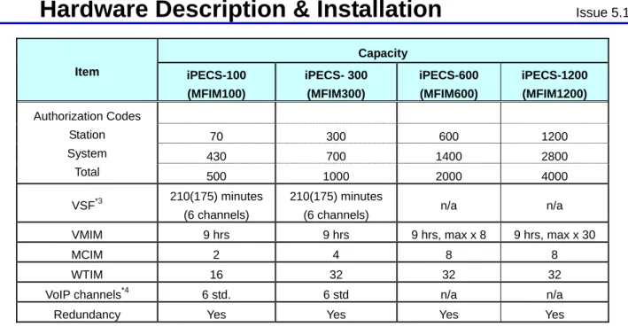
Table 3.1-1 System Capacities
Capacity Item iPECS-100 (MFIM100) iPECS- 300 (MFIM300) iPECS-600 (MFIM600) iPECS-1200 (MFIM1200)
Main Cabinet 10 slots 10 slots 10 slots 10 slot
System Ports 100 ports 300 ports 600 ports 1200 ports
Stations*1 70 300 600 1200 PSTN circuits*1 42 200 400 600 Max. RSGMs*2 35 150 300 600 Attendants 4 5 5 5 Serial Port (RS-232C) 1 1 1 1
USB Host port 1 1 1 port 1
Alarm/Door bell input 2 2 2 2
External Control
Relays 2 4 4 4
Music Source Inputs 2 2 2 2
Power Fail Circuit 4 4 + Ext. PFTU
(6 optional)
4 + Ext. PFTU (6 optional)
4 + Ext. PFTU (6 optional)
External Page zones 2 2 2 2
Internal Page Zones 10 35 35 100
System Speed Dial 800 (48 digits) 3000 (48 digits) 6000 (48 digits) 12000 (48 digits) System Speed Dial
Zones (Groups) 10 10 20 50
Station Speed Dial 20 (48 digits) 100 (48 digits) 100 (48 digits) 100 (48 digits) Last Number Redial 10 (48 digits) 10 (48 digits) 10 (48 digits) 10 (48 digits) Save Number Redial 1 (48 digits) 1 (48 digits) 1 (48 digits) 1 (48 digits)
DSS Consoles/Station 3 9 9 9
SMDR buffer 5000 10000 15000 30000
CO Line Groups 20 72 72 200
Station & Hunt Groups 40 48 48 100
Station & Hunt Group
Members 70 70 70 200 20 40 80 160 Conf. Grps - System Station 35 150 300 600 Executive/Secretary pairs 10 36 36 100
Capacity Item iPECS-100 (MFIM100) iPECS- 300 (MFIM300) iPECS-600 (MFIM600) iPECS-1200 (MFIM1200) 70 300 600 1200 430 700 1400 2800 Authorization Codes Station System Total 500 1000 2000 4000 VSF*3 210(175) minutes (6 channels) 210(175) minutes
(6 channels) n/a n/a
VMIM 9 hrs 9 hrs 9 hrs, max x 8 9 hrs, max x 30
MCIM 2 4 8 8
WTIM 16 32 32 32
VoIP channels*4 6 std. 6 std n/a n/a
Redundancy Yes Yes Yes Yes
Note 1 The station and CO Line maximums are not simultaneously; total ports cannot exceed the specified System Port capacity. Note 2 For maximum RSGM connection ports, calculation formula is ports = available system station ports)/2, there must be
sufficient VoIP channels to support packet relay for RSGM rtp packets.
Note 3 Approximately 35 minutes (16 Mbytes) of the VSF memory are used to provide basic system prompts, the remaining memory can be used for announcements and voice message storage. Values in parenthesis are the announcement and storage time available.
Note 4 Using G.711 codecs, 8 VoIP channels are available. Due to additional processing needs, complex codecs reduce the available channels; four (4) channels are available using G.723 or G.729.
3.1.1 Dimension and Weight
Table 3.1.1-1 Dimensions and Weight
ITEM HEIGHT (mm/in) WIDTH (mm/in) DEPTH (mm/in) WEIGHT (kg/lbs) Gateway Module 230/9.1. 38.8/1.5. 194.5/7.7 1.5/3.3 Main Cabinet, Enhanced 265.6/10.5 440/17.3 318.2/12.5 7.78/17.2
PSU 230/9.1 38.3/1.5 179.4/7.1 1.4/3.1
1U RMB 38.3/1.5 482.6/19 183.27.2 2/4.4
DHLD *1 146/5.7 111.5/4.4*1 128/5 0.4/0.9
WHLD 280/11.0 60/2.4 188.3/7.4 0.2/0.4
Note 1 The width of the Desk mount does not include approximately 40mm/3.2 inches for each installed module.