R
Aurora 8B/10B
Protocol Specification
Xilinx is disclosing to you this Specification (hereinafter "the Specification") for use in the development of designs in connection with semiconductor devices. Xilinx expressly disclaims any liability arising out of your use of the Specification. Xilinx does not convey any license under its patents, copyrights, or any rights of others in connection with the Specification. You are responsible for obtaining any rights you may require for your use or implementation of the Specification. Xilinx reserves the right to make changes, at any time, to the Specification without notice and at the sole discretion of Xilinx. Xilinx assumes no obligation to correct any errors contained in the Specification or to advise you of any corrections or updates. Xilinx expressly disclaims any liability in connection with technical support or assistance that may be provided to you in connection with the Specification.
THE SPECIFICATION IS DISCLOSED TO YOU "AS-IS" WITH NO WARRANTY OF ANY KIND. YOU BEAR THE ENTIRE RISK AS TO ITS IMPLEMENTATION AND USE. YOU ACKNOWLEDGE AND AGREE THAT YOU HAVE NOT RELIED ON ANY ORAL OR WRITTEN INFORMATION OR ADVICE, WHETHER GIVEN BY XILINX, ITS EMPLOYEES OR CONTRACTORS. XILINX MAKES NO OTHER WARRANTIES, WHETHER EXPRESS, IMPLIED, OR STATUTORY, REGARDING THE SPECIFICATION, INCLUDING ANY WARRANTIES OF MERCHANTABILITY, FITNESS FOR A PARTICULAR PURPOSE, OR NONINFRINGEMENT OF THIRD-PARTY RIGHTS.
IN NO EVENT WILL XILINX BE LIABLE FOR ANY CONSEQUENTIAL, INDIRECT, EXEMPLARY, SPECIAL, OR INCIDENTAL DAMAGES, INCLUDING ANY LOSS OF DATA OR LOST PROFITS, ARISING FROM OR RELATING TO YOUR USE OF THE SPECIFICATION, EVEN IF YOU HAVE BEEN ADVISED OF THE POSSIBILITY OF SUCH DAMAGES.
© 2002-2004, 2007, 2009-2010 Xilinx, Inc. XILINX, the Xilinx logo, Virtex, Spartan, ISE, and other designated brands included herein are trademarks of Xilinx in the United States and other countries. All other trademarks are the property of their respective owners.
Revision History
The following table shows the revision history for this document.
Date Version Revision
10/01/2014 2.3
Added Table 2-2, page 14 and flow control transmission priorities description. Revised Section 3.1.3 “Native Flow Control PDU Format,” page 21.
Corrected /SCP/ lane placement in Figure 5-8, page 41. Updated Table A-1, page 51.
04/19/2010 2.2 Clarified how electrical characteristics are defined in Section 6.1 “Overview.” 06/24/2009 2.1 Replaced instances of Aurora with Aurora 8B/10B. Corrected Figure 4-2, page 25. 09/19/2007 2.0
Removed 64B/66B feature. Clarified Section 4.2.1 “8B/10B Lane Initialization” and Figure B-3, page 65 and the Notes section in Figure 5-6, page 39 and Figure 5-8, page 41.
06/21/2004 1.3 Added 64B/66B feature.
10/17/2003 1.2
Miscellaneous edits to text and figures throughout.
Clarifications to State Machine Conventions in the preface, and Section 1 Introduction and Overview.
Added Overview to Section 2 Data Transmission and Reception.
Added sections 3.1.2 Native Flow Control Latency, and 3.1.4 User Flow Control Operation, and added Table 3-2 user flow control SIZE Encoding table to Section 3 Flow Control.
Corrected Lane Initialization procedure, and Channel Verification in Section 4 Initialization and Error Handling.
Additions to section 5.4.8 Idle Sequence, and section 5.4.11 Multi-Lane Striping and Transmission Rules in Section 5 PCS and PMA Layers.
Corrections to Section 6 Electrical Specification.
02/14/2003 1.1 Added Flow Control section. Edited text and figures for clarification. 10/16/2002 1.0 Initial Xilinx Release.
Revision History
. . . 3Preface: About This Specification
Open Standard Specification Contents
. . . 7Conventions
. . . 7Typographical . . . 7
Online Document . . . 8
Numerical . . . 8
Values of Literals . . . 8
State Diagram Conventions . . . 9
Section 1: Introduction and Overview
1.1:Introduction
. . . 111.2:
Scope
. . . 111.3:
Overview
. . . 12Section 2: Data Transmission and Reception
2.1:Overview
. . . 132.2:
8B/10B Data Transmission and Reception
. . . 132.2.1: Symbol-Pairs . . . 13
2.2.2: Data Ordering . . . 13
2.2.3: Transmission Scheduling . . . 13
2.2.4: User PDU Transmission Procedures . . . 15
2.2.5: User PDU Reception Procedures . . . 16
Section 3: Flow Control
3.1:Overview
. . . 193.1.1: Native Flow Control Operation . . . 20
3.1.2: Native Flow Control Latency . . . 21
3.1.3: Native Flow Control PDU Format . . . 21
3.1.4: User Flow Control Operation . . . 22
3.1.5: User Flow Control PDU Format . . . 22
Section 4: Initialization and Error Handling
4.1:Overview
. . . 234.2:
8B/10B Initialization and Error Handling
. . . 244.2.1: 8B/10B Lane Initialization . . . 24
4.2.2: 8B/10B Channel Bonding . . . 26
4.2.3: 8B/10B Channel Verification. . . 26
4.2.4: 8B/10B Error Handling . . . 27
R
Section 5: PCS and PMA Layers
5.1:
Overview
. . . 295.2:
PCS Layer Functions
. . . 295.3:
PMA Layer Functions
. . . 305.4:
8B/10B Transmission Code
. . . 315.4.1: Character and Code Group Notation . . . 32
5.4.2: Running Disparity . . . 33
5.4.3: Running Disparity Rules . . . 33
5.4.4: 8B/10B Encoding . . . 34 5.4.5: Transmission Order . . . 34 5.4.6: 8B/10B Decoding . . . 35 5.4.7: Ordered Sets . . . 35 5.4.8: Idle Sequence . . . 36 5.4.9: Clock Compensation . . . 38
5.4.10: Single-Lane Transmission Rules . . . 38
5.4.11: Multi-Lane Striping and Transmission Rules . . . 40
Section 6: Electrical Specifications
6.1:Overview
. . . 436.2:
Signal Definition
. . . 436.3:
Equalization
. . . 446.4:
Transmitter Specifications
. . . 446.5:
Receiver Specifications
. . . 466.6:
Receiver Eye Diagrams
. . . 48Appendix A: 8B/10B Coding Reference
A.1:8B/10B Encoding
. . . 51Appendix B: Aurora 8B/10B Serial Simplex Operation
B.1:Overview
. . . 61B.2:
Data Transmission and Reception
. . . 62B.3:
Flow Control
. . . 62B.4:
Initialization and Error Handling
. . . 62B.5:
Serial Simplex vs. Full-Duplex Operation
. . . 63B.5.1: Transmit Interface Lane initialization . . . 63
B.5.2: Receive Interface Lane Initialization . . . 65
B.5.3: Transmit Interface Channel Bonding Procedure . . . 66
B.5.4: Receive Interface Channel Bonding Procedure . . . 66
B.5.5: Transmit Interface Channel Verification Procedure . . . 66
B.5.6: Receive Interface Channel Verification Procedure . . . 67
B.5.7: Receive Interface Hard Error Procedure . . . 67
B.5.8: Use Models for Aurora 8B/10B Serial Simplex . . . 68
R
Preface
About This Specification
The Aurora 8B/10B protocol is a scalable, lightweight, link-layer protocol that can be used to move data point-to-point across one or more high-speed serial lanes. The Aurora 8B/10B protocol is an open standard and is available for implementation by anyone without restriction.
Open Standard Specification Contents
This Specification contains the following sections:
• Section 1, “Introduction and Overview”
• Section 2, “Data Transmission and Reception”
• Section 3, “Flow Control”
• Section 4, “Initialization and Error Handling”
• Section 5, “PCS and PMA Layers”
• Section 6, “Electrical Specifications”
• Appendix A, “8B/10B Coding Reference”
• Appendix B, “Aurora 8B/10B Serial Simplex Operation”
Conventions
This document uses the following conventions.
Typographical
The following typographical conventions are used in this document:
Convention Meaning or Use Example
Italic font
References to other manuals
See the Development System Reference Guide for more information.
Emphasis in text
If a wire is drawn so that it overlaps the pin of a symbol, the two nets are not connected. To emphasize a term the first time
it is used
The state machine uses one-hot
Preface: About This Specification R
Online Document
The following conventions are used in this document:
Numerical
Values of Literals
Literals are represented by specifying three of their properties as listed and shown in Figure P-1 and in Table P-1 and Table P-2, page 9:
1. Width in bits 2. Radix (Base) 3. Value
Table P-1 shows the Radix specifics: REG[FIELD]
Abbreviations or acronyms for registers are shown in uppercase text. Specific bits, fields, or ranges appear in brackets
REG[11:14]
Convention Meaning or Use Example
Convention Meaning or Use Example
Blue text Cross-reference link to a location in the current document
See the section “Additional Resources” for details. Refer to “Title Formats” in Section 1 for details.
Red text Cross-reference link to a location
in another document
See Figure 2-5 in the Virtex-5 FPGA User Guide.
Blue, underlined text Hyperlink to a website (URL) Go to http://www.xilinx.com for the latest speed files.
Convention Meaning or Use Example
n A decimal value
[n:m] Used to express a numerical range from n to m
x Unknown value
z High impedance
X-Ref Target - Figure P-1
Figure P-1: Properties of Literals
SP002_PF_01_031408
Conventions
R
All values are extended with zero except those with x or z in the most significant place; they extend with x or z respectively. A list of examples is shown in Table P-2:
State Diagram Conventions
This section describes the conventions used in the state diagrams for this document. The numbered sections correspond to the call-outs shown in the state machine diagram in Figure P-2.
Table P-1: Radix Specifics of Literals Radix Specifier Radix
b Binary d Decimal h Hexadecimal
o Octal
Table P-2: Examples of Extended Values
Number Value Comment
8’b0 00000000 An 8-bit binary number with value of zero.
(Zero extended to get 8 bits.)
8’bx xxxxxxxx An 8-bit binary number with value unknown.
(x extended to get 8 bits.)
8’b1x 0000001x An 8-bit binary number with value of 2 or 3, depending
on the value of x.
8’b0x 0000000x An 8-bit binary number with value of 0 or 1, depending
on the value of x.
8’hx xxxxxxxx An 8-bit hexadecimal number with value unknown.
(x extended to get 8 bits.)
8’hzx zzzzxxxx An 8-bit hexadecimal number with the upper four bits
not driven and the lower four bits unknown.
8’b1 00000001 An 8-bit binary number with value of one.
8’hz1 zzzz0001 An 8-bit hexadecimal number with the upper four bits
not driven and the lower four bits having value of one.
8’bx1 xxxxxxx1 An 8-bit binary number that is odd.
8’bx0 xxxxxxx0 An 8-bit binary number that is even.
8’hz zzzzzzzz An 8-bit hexadecimal number with value not driven.
(z extended to get 8 bits.)
8’h0z 0000zzzz An 8-bit hexadecimal number with upper nibble
specified and the lower not driven.
11’dn n An 11-bit decimal number with value n.
6’hn n A 6-bit hexadecimal number with value n.
Preface: About This Specification R
States
1. A state is represented by a rectangle. 2. The name of the state is indicated in bold.
State Transitions
3. State transition is indicated by an arrow annotated in italics.
State Machine Outputs
Outputs are shown in plain text. Outputs can be shown inside of state rectangles or can be part of the annotation associated with a transition arrow. If a signal is not listed in a state rectangle or on a transition arrow, its value at that time is 0 (not asserted). If a registered output does not appear in the state rectangle or transition arrow annotation, then its value is unchanged from the previous value.
Output Types
Outputs are divided into three classes as shown in the examples below. 4. Asserting control signals:
♦ go = 1
♦ link reset = 1 5. Register initialization:
♦ New Counter = 0
♦ xmit = /SP/ (an ordered set)
6. Incrementing or decrementing a register:
♦ New Counter = New Counter – 6
X-Ref Target - Figure P-2
Figure P-2: State Machine Diagram Conventions
SP002_PF_02_031408
- xmit = /SP/ - New Counter = 0
State ABC 0
go = 1 - New Counter = New Counter + 1
State ABC 1 New Counter = 3 New Counter = 3 2 5 3 1 4 reset 6 - Link Reset = 1
R
Section 1
Introduction and Overview
1.1 Introduction
The Aurora 8B/10B protocol is a scalable, lightweight, link-layer protocol that can be used to move data point-to-point across one or more high-speed serial lanes.
The Aurora 8B/10B is protocol independent and can be used to transport industry standard protocols, such as Ethernet and TCP/IP, or proprietary protocols. This allows designers of next-generation communication and computing systems to achieve higher connectivity performance while preserving software infrastructure investment.
While primarily targeted at chip-to-chip and board-to-board applications, the Aurora 8B/10B protocol can be used for box-to-box applications with the addition of standard optical interface components.
The Aurora 8B/10B protocol is an open standard and is available for implementation by anyone without restriction.
1.2 Scope
This section outlines what this specification does and does not define. The Aurora 8B/10B Protocol Specification defines the following:
• Physical layer interface: This includes the electrical levels, the clock encoding, and symbol coding.
• Initialization and error handling: This defines the steps required to prepare channel partners for communication across single lane and multi-lane channels. It also describes how the channel partners should behave in the presence of bit errors in the channel.
• Data striping: This describes how data is mapped across a channel of multiple serial lanes.
• Link layer: This describes how the beginning and end of user protocol data units (user PDUs) are marked during transmission. This also describes how data pauses may be inserted in data during transmission and how differences in clock rates between the transmitter and receiver are managed.
• Flow control: the Aurora 8B/10B protocol defines a link layer flow control mechanism and an expedited mechanism for forwarding higher layer user flow control messages.
Section 1: Introduction and Overview R
The Aurora 8B/10B protocol does not define the following; it is assumed that these features will be handled by higher-level protocols:
• Error detection and recovery: the Aurora 8B/10B protocol does not define a mechanism for detecting errors in user PDUs, or mechanisms for recovering from them beyond that provided by the 8B/10B encoding.
• Data switching: the Aurora 8B/10B protocol does not define an addressing scheme, therefore cannot support link layer multiplexing or switching.
1.3 Overview
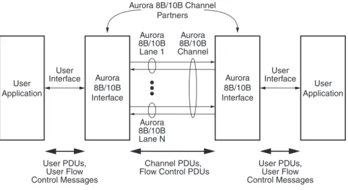
The Aurora 8B/10B protocol describes the transfer of user data across an Aurora 8B/10B channel. An Aurora 8B/10B channel consists of one or more Aurora 8B/10Blanes. Each Aurora 8B/10B lane is a full-duplex serial data connection. The devices that communicate across the channel are called channel partners. Figure 1-1 illustrates this relationship
The Aurora 8B/10B protocol interfaces transfer data and control to and from user applications by way of the user interface. The user interface is not defined in this specification.
Data flow consists of the transfer of user PDUs and user flow control messages between the user application and the Aurora 8B/10B interface, and the transfer of channel PDUs, and flow control PDUs across the Aurora 8B/10B channel. User PDUs can be of any length, but their format is not defined in this document. The format of the two types of flow control PDUs are defined in this document.
X-Ref Target - Figure 1-1
Figure 1-1: Aurora 8B/10B Channel Overview Aurora 8B/10B Lane 1 Aurora 8B/10B Interface Aurora 8B/10B Channel Aurora 8B/10B Lane N Aurora 8B/10B Channel Partners User Application User Application User Interface User Interface User PDUs, User Flow Control Messages User PDUs, User Flow Control Messages Channel PDUs,
Flow Control PDUs
Aurora 8B/10B Interface
R
Section 2
Data Transmission and Reception
2.1 Overview
This section describes the procedures for transmitting and receiving data across an Aurora 8B/10B channel. The Aurora 8B/10B protocol uses a symbol-based method.
2.2 8B/10B Data Transmission and Reception
2.2.1 Symbol-Pairs
The minimum unit of information that is transferred across an Aurora 8B/10B channel is two symbols, called a symbol-pair. The information on an Aurora 8B/10B channel (or lane) always comprises multiple symbol-pairs.
2.2.2 Data Ordering
Implementations of the Aurora 8B/10B protocol accept a stream of octets from user applications and transfer them across the Aurora 8B/10B channel as one or more streams of symbol-pairs. In all cases, the ordering of octet streams is preserved. For
implementations that have user interfaces that are more than one octet wide, the definition of octet ordering on that interface is implementation specific.
2.2.3 Transmission Scheduling
The following symbol six types of data are transmitted over an Aurora 8B/10B channel:
• Clock Compensation Sequences:
Sequences of control symbols used to prevent overrun of the receiver due to differences in clock rate between channel partners. Clock compensation sequences are described in Section 5.4.9 “Clock Compensation,” page 38.
• Initialization Sequences:
Four ordered sets that are used with the idle sequence to prepare an Aurora 8B/10B channel for data transmission during initialization. These ordered sets and their use are described in Section “Initialization and Error Handling,” page 23.
• Native Flow Control PDUs:
Link layer flow control PDUs generated by and interpreted by Aurora 8B/10B interfaces. These PDUs are described in Section 3.1.3 “Native Flow Control PDU Format,” page 21.
Section 2: Data Transmission and Reception R
In the event that several of the processes that generate these data types are prepared to transmit data at the same time, they are prioritized as shown in Table 2-1.
The data type priority should shift when the transmitter is processing a flow control request. During native flow control countdown or user flow control countdown, idle sequences have higher priority over channel PDUs. Since idles are always transmitted when no higher priority data type is available, this shift in priority effectively prevents frame transmission until the flow control countdown is complete (see “Flow Control” in Chapter 3 for details). Table 2-2 shows the relative data type priority while a flow control countdown is in progress.
• User Flow Control PDUs:
Flow control messages generated by, and interpreted by user applications, and encapsulated for transmission into user flow control PDUs. These are described in Section 3.1.5 “User Flow Control PDU Format,” page 22.
• Channel PDUs: User PDUs encapsulated for transmission over the Aurora 8B/10B channel. These are described in Section 2.2.4 “User PDU Transmission Procedures,” page 15.
• Idle Sequences: Sequences of control symbols that are transmitted whenever there is no data to send. Idle sequences are described in Section 5.4.8 “Idle Sequence,” page 36.
Table 2-1: Transmission Priorities
Data Type Priority
Clock Compensation Sequences Highest Initialization Sequences
Native Flow Control PDUs User Flow Control PDUs Channel PDUs
Idle Sequences Lowest
Table 2-2: Transmission Priorities During Flow Control Countdown
Data Type Priority
Clock Compensation Sequences Highest Initialization Sequences
Native Flow Control PDUs User Flow Control PDUs Idle Sequences
8B/10B Data Transmission and Reception
R
2.2.4 User PDU Transmission Procedures
Transmission of user PDUs requires the following procedures:
• Padding
• Encapsulation with channel PDU delimiters
• 8B/10B encoding of channel PDU payload
• Serialization and clock encoding
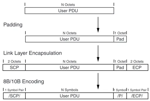
Figure 2-1 illustrates how user PDUs are mapped to channel PDUs by these procedures. Note that this figure illustrates the case where a pad octet is required. The remainder of this section describes these procedures in more detail.
2.2.4.1 Padding
The Aurora 8B/10B channel requires that all transmissions consist of an even number of symbols. To meet this requirement, all user PDUs that contain an odd number of octets must be padded with a single octet. This pad octet has a value of 0x9C and immediately follows the user PDU.
2.2.4.2 Link Layer Encapsulation
The user PDU is encapsulated with control symbol sequences, called ordered sets, to produce the complete channel PDU. These ordered sets demarcate the beginning and end of channel PDUs within the serial data stream. The Aurora 8B/10B protocol uses an /SCP/ (/K28.2/K27.7/) ordered set to mark the start of channel PDUs, and an /ECP/
(/K29.7/K30.7/) ordered set to mark the end of channel PDUs. The details of these ordered sequences can be found in Section 5.4.7 “Ordered Sets,” page 35.
X-Ref Target - Figure 2-1
Figure 2-1: Transmission Procedures
/SCP/ User PDU /P/
User PDU User PDU
Pad
/ECP/
1 Symbol Pair N Symbols 1 Symbol1 Symbol Pair
1 Octet N Octets
N Octets
Link Layer Encapsulation
8B/10B Encoding
Padding
SP002_02_01_101703
SCP User PDU Pad ECP
Section 2: Data Transmission and Reception R
2.2.4.3 8B/10B Encoding
After padding, the resulting data structure is referred to as the link layer payload. Prior to transmission the link layer payload is 8B/10B encoded by the physical coding sublayer
(PCS). All characters, with the exception of the pad octet, are encoded as data symbols. The pad octet is encoded as a /P/ (/K28.4/) control symbol to facilitate stripping at the receiving end. The details of the encoding process are described in Section 5.4.4 “8B/10B Encoding,” page 34.
2.2.4.4 Serialization and Clock Encoding
After the complete channel PDU has been assembled and encoded, it is serialized for transmission. The details of this process are described in Section 5.4.5 “Transmission Order,” page 34. The serialized data stream is transmitted in differential non return to zero
(NRZ) format.
2.2.5 User PDU Reception Procedures
Reception of user PDUs involves the following procedures:
• Deserialization
• 8B/10B decoding of channel PDU payload
• Link layer stripping
• Pad stripping
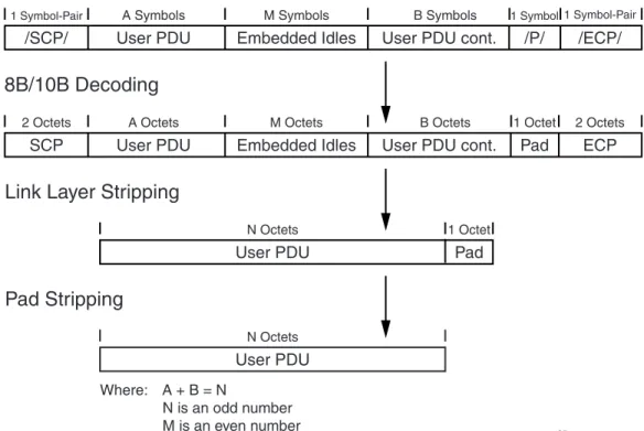
Figure 2-2 illustrates how user PDUs are mapped to channel PDUs by these procedures. Note that this figure illustrates the case where a pad octet was added to the user PDU data. The remainder of this section describes these procedures in more detail.
X-Ref Target - Figure 2-2
/SCP/ User PDU Embedded Idles User PDU cont. /P/
User PDU
User PDU
Pad
/ECP/
1 Symbol-Pair A Symbols M Symbols B Symbols 1 Symbol1 Symbol-Pair
1 Octet N Octets
N Octets
Link Layer Stripping
8B/10B Decoding
Pad Stripping
SCP User PDU Embedded Idles User PDU cont. Pad ECP
2 Octets A Octets M Octets B Octets 1 Octet 2 Octets
Where: A + B = N
N is an odd number M is an even number
8B/10B Data Transmission and Reception
R
2.2.5.1 Deserialization
The serial data stream is received in differential NRZ format. The receive logic deserializes this data into 10-bit data and control symbols. The details of this process are described in Section 5.4.5 “Transmission Order,” page 34.
Symbol alignment within the stream is established during the lane initialization procedure described in Section 4.2.1 “8B/10B Lane Initialization,” page 24 and is not performed again during normal channel operation.
2.2.5.2 8B/10B Decoding
After deserialization, the link layer payload is decoded into a stream of octets. The details of the 8B/10B decoding process are described in Section 5.4.6 “8B/10B Decoding,” page 35. During the decode process, the presence of a /P/ (/K28.4/) control symbol followed by an/ECP/ (/K29.7/K30.7/) in the data stream must be flagged so that the pad octet can be stripped during the pad stripping procedure.
2.2.5.3 Link Layer Stripping
The link layer stripping procedure removes channel PDU encapsulation and any embedded idle ordered sets that may have been inserted during transmission.
Removal of channel PDU encapsulation includes the /SCP/ (/K28.2/K27.7/) ordered set to mark the start of channel PDUs, and an /ECP/ (/K29.7/K30.7/) ordered set to mark the end of channel PDUs. The details of these ordered sequences can be found in
Section 5.4.7 “Ordered Sets,” page 35.
Removal of idle ordered sets involves the removal of /K/ (/K28.5/), /R/ (/K28.0/), and /A/ (/K28.3/) symbols. Any number of these symbols can appear at any point in the channel PDU with the following restrictions:
• An even number of idle symbols must have been inserted
• The start of the idle sequence must begin after an even number of symbols in the channel PDU
2.2.5.4 Pad Stripping
If a /P/ (/K28.4/) control symbol followed by /ECP/ (/K29.7/K30.7/) was detected during the 8B/10B decoding process, a pad octet was post-pended to the user PDU by the transmission process in order to meet channel alignment requirements. This octet, which has a value 0x9C after decoding, shall be stripped from the end of the data stream before passing it to the user application.
R
Section 3
Flow Control
3.1 Overview
This chapter describes the optional flow control mechanisms supported by the Aurora 8B/10B protocol. These mechanisms provide low-latency flow control to prevent data loss due to differences between the rate at which data is sourced and sunk between channel partners. Latency is minimized because flow control PDUs can be embedded within channel
PDUs (see Section 2.2.3 “Transmission Scheduling,” page 13).
The Aurora 8B/10B protocol supports the following two flow control mechanisms:
Figure 3-1, page 20 illustrates how these flow control schemes interrelate.
Native flow control PDUs are typically generated when elasticity storage at the receiver side is being depleted. Note that these PDUs must be generated early enough that the latency between the time that they are issued and when traffic stops does not result in an overflow of elasticity storage.
User flow control messages are forwarded from one user application to the other through the Aurora 8B/10B channel and are not interpreted by either Aurora 8B/10B interface. Some things to note about the flow control mechanisms:
• Assertion of native flow control does not block the forwarding of user flow control PDUs
• User flow control PDUs, once their transmission has started, cannot be interrupted by any other sequence
• Native Flow Control: This is a link-layer flow control mechanism. Native flow control PDUs are generated by, and interpreted by the Aurora 8B/10B interface.
• User Flow Control: This mechanism can be used to implement user-defined flow control schemes at any layer. User flow control messages are generated by, and interpreted by the user application. The Aurora 8B/10B interface encapsulates these messages into user flow control PDUs, and provides a low latency mechanism for their transport across the channel.
Section 3: Flow Control R
3.1.1 Native Flow Control Operation
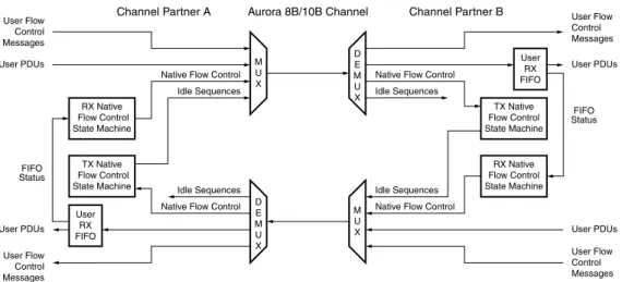
Operation of native flow control is governed by the two state machines shown in Figure 3-1.
The RX native flow control state machine monitors the state of the RX FIFO, and generates native flow control PDUs when there is a risk of RX FIFO overflow. These PDUs request that the channel partner pause the transmission of user PDUs for a specified number of
symbol times. The format of these native flow control PDUs is described in
Section 3.1.3 Native Flow Control PDU Format. The algorithm used to map the state of the FIFO to a specific native flow control PDU is implementation dependent, and is not defined in this specification.
The TX native flow control state machine responds to native flow control PDUs from the channel partner by pausing the transmission of user PDUs for the requested interval. Note that in addition to idle sequences, a pause can include the transmission of native flow control PDUs or user flow control PDUs since neither of these PDUs are stored in the RX FIFO. If the Aurora 8B/10B interface is in the process of transmitting a user PDU, the TX native flow control state machine can respond in one of two ways to native flow control PDUs.
All Aurora 8B/10B protocol implementations must be capable of supporting either behavior if they support flow control. The operating mode must be programmable, but this specification does not define how the operating mode is chosen.
X-Ref Target - Figure 3-1
Figure 3-1: Flow Control Overview User RX FIFO RX Native Flow Control State Machine TX Native Flow Control State Machine
Native Flow Control M U X D E M U X FIFO Status
Channel Partner A Aurora 8B/10B Channel User Flow Control Messages User Flow Control Messages User PDUs User PDUs
Native Flow Control Idle Sequences TX Native Flow Control State Machine RX Native Flow Control State Machine Native Flow Control
M U X D E M U X FIFO Status Channel Partner B User Flow Control Messages User Flow Control Messages User PDUs User PDUs Native Flow Control
Idle Sequences
Idle Sequences Idle Sequences
SP002_06_01_050609
User RX FIFO
• Completion Mode: The user PDU is completed before transmission is paused.
Overview
R
3.1.2 Native Flow Control Latency
When operating in immediate mode, the maximum round trip delay contribution from the channel partners is defined, in order to bound the depth of the User RX FIFO. The contribution to latency introduced by the channel is not included in this definition, but must also be taken into account when designing the User RX FIFO for a particular channel. The round trip delay through the Aurora 8B/10B interfaces between the native flow control PDU request and the first pause arriving at the originating channel partner must not exceed 256 symbol times.
3.1.3 Native Flow Control PDU Format
Native flow control PDUs are two octets in length. The first octet is an SNF (start of native flow control) character and the second octet is a data character called the command octet. The command octet contains the PAUSE field, which specifies the number of clock cycles the idle characters must send in response to the PDU by the channel partner. Figure 3-2 shows the command octet format, and Table 3-1 shows the encoding of the PAUSE field.
All native flow control PDUs transmitted on the same cycle must carry the same PAUSE code and XOFF bit setting. When multiple native flow control PDUs arrive on the same clock cycle, the receiver must process only one PDU, choosing any of the PDUs for processing.
X-Ref Target - Figure 3-2
Figure 3-2: Native Flow Control Command Octet Format Table 3-1: Native Flow Control PAUSE Field Encoding
PAUSE Field Contents PAUSE Interval (Symbols)
0000 0 (XON) 0001 2 0010 4 0011 8 0100 16 0101 32 0110 64 0111 128 1000 256 1001 to 1110 Reserved 1111 Infinite (XOFF) 0000 4 bits 4 bits 8 bits PAUSE SNF Reserved UG002_06_02_020603
Section 3: Flow Control R
3.1.4 User Flow Control Operation
User flow control PDUs are not interruptible by clock compensation sequences, native flow control PDUs, or idle sequences once their transmission has begun. The Aurora 8B/10B protocol implementations may need to buffer user flow control PDUs to ensure that they are not interrupted, and that the clock compensation rules are met. Any buffering scheme is implementation dependent and is not defined in this specification.
3.1.5 User Flow Control PDU Format
User flow control PDUs are 4 to 18 octets in length. The first octet is an SUF (start of user flow control) character, which is followed by a data character called the command octet. This command octet is immediately followed by 2 to 16 octets of the flow control message from the user application.
Note: The /K28.4/ symbol is used for both an SUF character and a pad character for channel PDUs. However the pad character can only be followed by a control character, and can never be followed by a data character. This discriminates between a /K28.4/ used as a pad character and a /K28.4/ used to mark the start of a user flow control PDU.
Figure 3-3 shows the format of the user flow control PDU. The length of the user flow control message is specified in the SIZE field. The user flow control message size can be any even number of octets from 2 to 16 as shown in Table 3-2.
X-Ref Target - Figure 3-3
Figure 3-3: User Flow Control PDU Format
Table 3-2: SIZE Encoding SIZE Field
Contents
User Flow Control Message Size 000 2 octets 001 4 octets 010 6 octets 011 8 octets 100 10 octets 101 12 octets 110 14 octets 111 16 octets 00000 3 bits 8 bits 5 bits 2 to 16 octets of User Flow Control
Message SIZE
SUF
Reserved UG002_06_03_101403
R
Section 4
Initialization and Error Handling
4.1 Overview
This chapter describes the initialization procedures needed to prepare an Aurora 8B/10B channel for data transmission and reception. Initialization of an Aurora 8B/10B channel is a three-stage process. These stages are:
Figure 4-1 illustrates how these procedures interrelate. During channel verification, all lanes
must become ready to receive data across the channel. When an Aurora 8B/10B interface completes channel verification, it can immediately start to transmit data.
• Lane Initialization: This procedure is performed individually on each lane to activate the link and align the received data to the proper boundaries.
• Channel Bonding: This procedure bonds the individual lanes into a single data channel. If the function implemented only uses a single link, channel bonding is not required and will be bypassed. Channel bonding eliminates skew introduced from various sources including the trace lengths, connectors and IC variations.
• Channel Verification: This procedure performs any alignment needed to map received data to the user interface and verifies the ability of the channel to transfer valid data.
X-Ref Target - Figure 4-1
Figure 4-1: Initialization Overview
SP006_04_01_060607
Power-Up, Reset, Channel Failure
Lane Initialization Channel Bonding Channel Verification Multi-Lane Channel Single-Lane Channel Channel Ready Initialize Lane Hardware
and Symbol Alignment
Bond Lanes
Check Channel Integrity and Data Alignment
Verification Complete Verification
Timeout
Channel Bonding Timeout
Section 4: Initialization and Error Handling R
4.2 8B/10B Initialization and Error Handling
4.2.1 8B/10B Lane Initialization
The individual lane initialization procedure synchronizes each lane transceiver with its lane partner upon reset or channel failure. A channel failure is defined as any one of the following conditions:
• Excessive channel data errors, as defined in Section 4.2.4 “8B/10B Error Handling”
• Excessive protocol violations, implementation defined
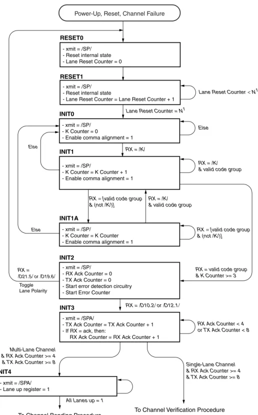
A state diagram of the lane initialization procedure is shown in Figure 4-2, page 25. See Table 5-1, page 35 for the definition of /SP/, /K/, and /SPA/.
8B/10B Initialization and Error Handling
R
Note: See “State Diagram Conventions,” page 9 for conventions used in this diagram.
X-Ref Target - Figure 4-2
Figure 4-2: Lane Initialization Procedure - xmit = /SPA/
- TX Ack Counter = TX Ack Counter + 1 - If RX = ack, then:
RX Ack Counter = RX Ack Counter + 1 RX = /K/
RX = /K/ & valid code group - xmit = /SP/
- Reset internal state - Lane Reset Counter = 0 RESET0
- xmit = /SP/
- K Counter = K Counter + 1 - Enable comma alignment = 1 INIT1 INIT2 INIT4 - xmit = /SPA/ - Lane up register = 1 - xmit = /SP/ - RX Ack Counter = 0 - TX Ack Counter = 0 - Start error detection circuitry - Start Error Counter
RX = valid code group & K Counter >= 3
To Channel Bonding Procedure RX = /D21.5/ or /D19.6/ Else Else INIT3 RX = /D10.2/ or /D12.1/ RX Ack Counter < 4 or TX Ack Counter < 8 Toggle Lane Polarity - xmit = /SP/ - Reset internal state
- Lane Reset Counter = Lane Reset Counter + 1 RESET1
Lane Reset Counter = N1
Lane Reset Counter<N1
Else
Multi-Lane Channel & RX Ack Counter >= 4 & TX Ack Counter >= 8
- xmit = /SP/ - K Counter = 0
- Enable comma alignment = 1 INIT0
RX = [valid code group & (not /K/)]
RX = [valid code group & (not /K/)]
RX = /K/ & valid code group
- xmit = /SP/
- K Counter = K Counter - Enable comma alignment = 1 INIT1A
Power-Up, Reset, Channel Failure
To Channel Verification Procedure Single-Lane Channel & RX Ack Counter >= 4 & TX Ack Counter >= 8
SP002_04_02_052009
Section 4: Initialization and Error Handling R
4.2.2 8B/10B Channel Bonding
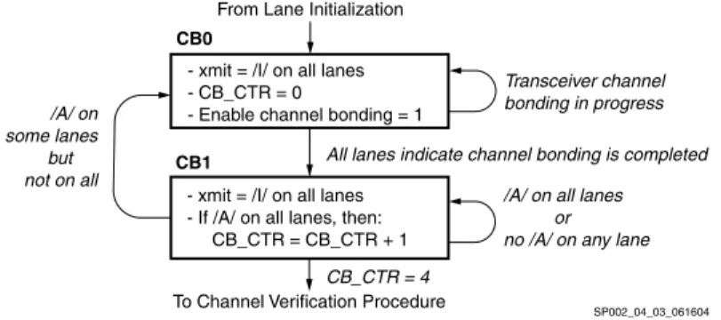
The channel bonding procedure aligns all data being received by each lane. Channel bonding cannot begin until each lane has completed the lane initialization procedure. Figure 4-3 shows a state diagram of the channel bonding procedure. See Table 5-1, page 35 for the definition of /I/ and /A/.
Note: See “State Diagram Conventions,” page 9 for conventions used in this diagram.
Channel bonding occurs in two phases. This first phase, which corresponds to State CB0 in Figure 4-3, consists of transceiver specific data alignment. The second phase, which corresponds to State CB1, verifies that the transceivers have aligned correctly and are delivering the /A/ ordered sets within the /I/ ordered set at the same time.
4.2.3 8B/10B Channel Verification
The channel verification procedure is used to align data across the user interface, and verify channel integrity. It essentially consists of sending the channel verification sequence across all lanes in each direction. Using this known data pattern, the receiving channel partners can correctly align data across the user interface, and verify channel integrity. A diagram of the procedure is shown in Figure 4-4. See Table 5-1, page 35 for the definition of /V/.
X-Ref Target - Figure 4-3
Figure 4-3: Channel Bonding Procedure - xmit = /I/ on all lanes
- If /A/ on all lanes, then: CB_CTR = CB_CTR + 1
From Lane Initialization
To Channel Verification Procedure
All lanes indicate channel bonding is completed
/A/ on all lanes or no /A/ on any lane - xmit = /I/ on all lanes
- CB_CTR = 0
- Enable channel bonding = 1
CB_CTR = 4 /A/ on some lanes but not on all CB0 CB1 Transceiver channel bonding in progress SP002_04_03_061604
X-Ref Target - Figure 4-4
Figure 4-4: Channel Verification Procedure - xmit = verification sequence1 across channel
- RX CV Counter = 0 - TX CV Counter = 0
CV0
- xmit = verification sequence1 across channel
- If TX = /V/ then: TX CV Counter = TX CV Counter + 1 - If RX = /V/ then: RX CV Counter = RX CV Counter + 12 Bad /V/ Go to Lane Initialization Procedure
State RESET0
Else
RX CV Counter = at least 4 & TX CV Counter = at least 8
CV1
From Channel Bonding Procedure If Multi-Lane Channel From Lane Initialization Procedure
If Single-Lane Channel
Initialization Complete, Channel Ready
Note: 1) The verification sequence consists of the following pattern: 60 /I/ symbols followed by the four-symbol /V/ ordered set 2) When all of the lane receivers have received the third /V/ ordered set from their lane partners, the channel receiver portion of the receiver, if not already enabled, must be enabled to prevent loss of data.
8B/10B Initialization and Error Handling
R
4.2.4 8B/10B Error Handling
During the normal transmission of data, it is possible for the channel to fail. All lanes must be individually monitored for errors. Before the serial transceiver properly byte aligns the data, many errors will be seen on the outputs. Because of this, it is important that none of the error detection circuits is activated until the lane is stable. This stable point is achieved when the K counter reaches 3, as shown in Figure 4-2, page 25. Once the K counter has reached 3, all error detection circuits should be activated.
There are two types of errors: hard and soft. A hard error occurs when:
• There is an overflow/underflow in either the transmit or receive elastic buffers
• There are too many soft errors, refer to Figure 4-5, page 28
• The channel partner undergoes a reset, indicated by receipt of initialization sequences
• The physical connection between channel partners is broken
Hard errors are considered catastrophic errors, after which the channel should immediately be re-initialized. Any data unit being received when a hard error occurs is corrupt and should be discarded.
Soft errors are typically due to transient bit errors on the lane. Soft errors do not necessarily require the channel to be reset. The Aurora 8B/10B protocol does no explicit data error checking; data errors induced by soft errors should be detected and corrected by the user's error handling capability. Examples of soft errors include:
• Disparity errors
• Symbol errors
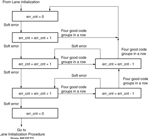
In multi-Gbps systems, a bit error can occur in a range between minutes, for a system with poor channel integrity, to days or years for a system with good channel integrity. As a result, Aurora 8B/10B interfaces must implement soft error monitoring logic to verify ongoing channel integrity. This logic consists of a soft error counter and associated control logic for each lane. Figure 4-5, page 28 illustrates the required behavior of the soft error monitoring logic.
Section 4: Initialization and Error Handling R
X-Ref Target - Figure 4-5
Figure 4-5: Soft Error Handling
err_cnt = 0 From Lane initialization
Soft error
err_cnt = err_cnt + 1 Soft error
err_cnt = err_cnt + 1 Soft error
err_cnt = err_cnt + 1 err_cnt = err_cnt - 1
Soft error
Soft error
err_cnt = err_cnt - 1 Soft error
Four good code groups in a row
Four good code groups in a row Four good code
groups in a row
Four good code groups in a row
Four good code groups in a row
Go to
Lane Initialization Procedure State RESET0
err_cnt = 0
R
Section 5
PCS and PMA Layers
5.1 Overview
This chapter specifies the functions provided by the physical coding sublayer (PCS) and
physical medium attachment (PMA) sublayer (the PCS and PMA terminology is adopted from IEEE Std 802.3 [Ref 1]). While the Aurora 8B/10B protocol does not explicitly implement these sublayers, the physical layer functions that are part of the Aurora 8B/10B protocol are described using this conceptual model.
The topics include:
• 8B/10B coding
• Character representation
• Data stream serialization
• Code groups
• Columns
• Channel transmission rules
• Idle sequences
• Channel initialization
This section also describes how data is striped across lanes when the channel is made up of more than one lane. An Aurora 8B/10B channel is made up of one or more Aurora 8B/10B lanes, each of which is a full-duplex serial connection (see Section 1.3 “Overview,” page 12 for details).
5.2 PCS Layer Functions
The physical coding sublayer (PCS) function is responsible for idle sequence generation, lane striping, and encoding for transmission. Upon reception, the PCS is responsible for decoding, lane alignment, and destriping. The PCS in a standard implementation uses an 8B/10B encoding for transmission over the channel. See BYTE ORIENTED DC BALANCED (0,4) 8B/10B PARTITIONED BLOCK TRANSMISSION CODE [Ref 2], for the source of the 8B/10B encoding scheme.
The PCS layer also provides mechanisms to detect lane states. It provides for clock difference tolerance between the sender and receiver without requiring flow control. The The Aurora 8B/10B protocol does not include mechanisms for determining the number of lanes that make up the channel. Each channel partner must be configured for operation over the same number of lanes.
Section 5: PCS and PMA Layers R
• Dequeues channel PDUs, native flow control PDUs, user flow control PDUs and delimited control symbols awaiting transmission as a character stream
• Stripes the transmit character stream across the available lanes
• Generates the idle sequence and inserts it into the transmit character stream for each lane when no PDUs or delimited control symbols are available for transmission
• Encodes the character stream of each lane independently into 10-bit parallel code groups
• Passes the resulting 10-bit parallel code groups to the PMA The PCS layer performs the following receive functions:
• Decodes the received stream of 10-bit parallel code groups for each lane independently into characters
• Marks characters decoded from invalid code groups as invalid
• Aligns the character streams to eliminate the skew between the lanes and reassembles (destripes) the character stream from each lane into a single character stream, if the channel is using more than one lane
• Delivers the decoded character stream of PDUs and delimited control symbols to the higher layers
5.3 PMA Layer Functions
The physical medium attachment (PMA) function is responsible for serializing 10-bit parallel code groups to/from a serial bitstream on a lane-by-lane basis. Upon receiving data, the PMA function aligns the received bitstream into 10-bit code group boundaries, independently on a lane-by-lane basis. It then provides a continuous stream of 10-bit code groups to the PCS, one stream for each lane. The 10-bit code groups are not observable by layers higher than the PCS.
8B/10B Transmission Code
R
5.4 8B/10B Transmission Code
The 8B/10B transmission code used by the PCS encodes 9-bit characters (eight bits of information and one control bit) into 10-bit code groups for transmission, and reverses the process on reception. Encodings are defined for 256 data characters and 12 special (control) characters.
The code groups used by the transmission code are either balanced or unbalanced. A balanced code group has an equal number of ones and zeros and an unbalanced code group has an unequal number of zeros. This selection of code groups guarantees a minimum of three transitions, 0 to 1 or 1 to 0, within each code group, while maintaining DC balance.
The 8B/10B code uses disparity to keep track of the number of ones and zeros it has sent and received. A code group that has two more ones than zeros is assigned a positive disparity. A code group that has two more zeros than ones is assigned a negative disparity. A code group that has an equal number of ones and zeros is assigned a zero disparity. The encoder maintains DC balance by never transmitting a second code group of the same disparity without first transmitting a code group of the opposite disparity. This rule does not apply to code groups with zero disparity. The complete definition is in
Section 5.4.3 “Running Disparity Rules,” page 33. The 8B/10B code has the following properties:
• Sufficient bit transition density (three to eight transitions per code group) to allow clock recovery by the receiver
• Special code groups that are used for establishing the receiver synchronization to the 10-bit code group boundaries, delimiting control symbols, and maintaining receiver bit and code group boundary synchronization
• DCbalanced
Section 5: PCS and PMA Layers R
5.4.1 Character and Code Group Notation
This section describes the notation for characters, code groups, and their bits used in 8B/10B encoding and decoding.
The information bits [0-7] of an unencoded character are denoted with the letters A
through H where the letter H denotes the most significant information bit (bit 0) and the letter A denotes the least significant information bit (bit 7). This is shown in Figure 5-1. Each data character has a representation of the form Dx.y where x is the decimal value of the least significant five information bits EDCBA, and y is the decimal value of the most significant three information bits HGF, as shown in Figure 5-1. Each control character has a similar representation using the form Kx.y.
The output of the 8B/10B encoding process is a 10-bit code group. The bits of a code group are denoted with the letters a through j. The bits of a code group are all of equal
significance, there is no most significant or least significant bit. The ordering of the code group bits is shown in Figure 5-2.
The code groups corresponding to the data character Dx.y is denoted by /Dx.y/. The code groups corresponding to the special character Kx.y are denoted by /Kx.y/
X-Ref Target - Figure 5-1
Figure 5-1: Character Notation Example (D25.3)
X-Ref Target - Figure 5-2
Figure 5-2: Code Group Notation Example (/D25.3/)
D25.3 HGF 011 EDCBA 11001 y = 3 x = 25 sp002_03_01_081302 /D25.3/ abcdei 100110 fghj 1100 from x term sp002_03_02_082102 from y term
8B/10B Transmission Code
R
5.4.2 Running Disparity
The 8B/10B encoding and decoding functions use a binary variable called running disparity. The variable can have a value of either positive (RD+) or negative (RD-). The encoder and decoder each have a running disparity variable for each lane, which are all independent of each other.
The primary use of running disparity in the encoding process is to keep track of whether the encoder has output either more ones or more zeros. The current running disparity value is used to select which unbalanced code group will be used when the encoding for a character requires a choice between two unbalanced code groups.
The primary use of running disparity in the decoding process is to detect errors. Bit error(s) will transform a 10-bit code group into either an invalid code group or a different valid code group. For those code groups that were transformed into another valid code group, running disparity will catch all instances caused by a single bit error and some instances caused by multiple bit errors. When a running disparity error is flagged, the error can be either in that code group or in an earlier code group.
5.4.3 Running Disparity Rules
After power-up and before the channel is operational, both the transmitter (encoder) and receiver (decoder) must establish current values of running disparity. The transmitter shall use a negative value as the initial value for the running disparity for each lane.
The receiver may use either a negative or positive initial value of running disparity for each lane.
The following algorithm shall be used for calculating the running disparity for each lane. In the encoder, the algorithm operates on the code group that has just been generated by the encoder. In the receiver, the algorithm operates on the received code group that has just been decoded by the decoder.
Each code group is divided to two sub-blocks as shown in Figure 5-2, page 32, where the first six bits abcdei form one 6-bit sub-block and the second four bits fghj form a second 4-bit sub-block. The running disparity value at the beginning of the 6-bit sub-block is the value determined at the end of the previous code group. Running disparity at the beginning of the 4-bit sub-block is the running disparity at the end of the 6-bit sub-block. The running disparity value at the end of the code group is the value determined at the end of the 4-bit sub-block.
The sub-block running disparity shall be calculated as follows:
1. The running disparity is positive if at the end of any sub-block the sub-block contains more ones than zeros. It is also positive if at the end of a 4-bit sub-block the sub-block has the value 4’b0011, and if at the end of a 6-bit sub-block the sub-block has the value 6’b000111.
2. The running disparity is negative if at the end of any sub-block, the sub-block contains more zeros than ones. It is also negative if at the end of a 4-bit sub-block, the sub-block has the value 4’b1100, and if at the end of a 6-bit sub-block, the sub-block has the value 6’b111000.
3. In all other cases, the value of the running disparity at the end of the sub-block is the same as the value at the beginning of the sub-block (the running disparity is
Section 5: PCS and PMA Layers R
5.4.4 8B/10B Encoding
The 8B/10B encoding function encodes 9-bit characters into 10-bit code groups. The encodings for the 256 data characters (Dx.y) are specified in Table A-1, page 51. The encodings or the 12 control characters (Kx.y) are specified in Table A-2, page 59. Both tables have two columns of encodings, one marked RD- and one marked RD+. When encoding a character, the code group in the RD- column is selected if the current value of encoder running disparity is negative. The code group in the RD+ column is selected if the current value of encoder running disparity is positive.
Data characters (Dx.y) shall be encoded according to Table A-1, page 51 and the current value of encoder running disparity. Special characters (Kx.y) shall be encoded according to Table A-1, page 51 and the current value of encoder running disparity. After each character is encoded, the resulting code group shall be used by the encoder to update the running disparity according to Section 5.4.3 “Running Disparity Rules,” page 33.
5.4.5 Transmission Order
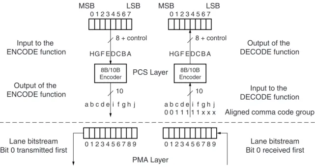
The 10-bit parallel output of the encoder shall be serialized and transmitted with bit a
transmitted first and a bit ordering of abcdei fghj as shown in Figure 5-3.
Figure 5-3 gives an overview of a character passing through the encoding, serializing, transmission, deserializing, and decoding processes. The left side of the figure shows the transmit process of encoding a character stream using 8B/10B encoding and the 10-bit serialization. The right side shows the reverse process of the receiver deserializing and using 8B/10B decoding on the received code groups.
The dashed line shows the functional separation between the PCS layer, that provides 10-bit code groups, and the PMA layer.
The drawing also shows, on the receive side, the bits of a special character containing the comma pattern that is used by the receiver to establish 10-bit code-boundary
synchronization.
X-Ref Target - Figure 5-3
0 1 2 3 4 5 6 7 7 8 9 0 1 2 3 4 5 6 0 1 2 3 4 5 67 8 9 HG F E DC B A HG F E DC B A LSB MSB 8B/10B Encoder a b c d e i f g h j 0 1 2 3 4 5 6 7 LSB MSB 8B/10B Encoder a b c d e i f g h j 0 0 1 1 1 1 1 x x x 10 10 8 + control 8 + control PCS Layer PMA Layer Input to the ENCODE function Output of the ENCODE function Lane bitstream Bit 0 transmitted first
Lane bitstream Bit 0 received first
Output of the DECODE function
Input to the DECODE function Aligned comma code group
8B/10B Transmission Code
R
5.4.6 8B/10B Decoding
The 8B/10B decoding function decodes received 10-bit code groups into 9-bit characters. It also detects received code groups that have no defined decoding and marks the resulting characters in the output stream invalid.
The decoding function uses Table A-1, page 51, Table A-2, page 59, and the current value of the decoder running disparity. To decode a received code group, the decoder shall select the RD- column of Table A-1, page 51 and Table A-2, page 59 if the current value of the decoder running disparity is negative or the RD+ column if the value is positive. The decoder shall then compare the received code group with the code groups in the selected column of both tables. If a match is found, the code group is decoded to the associated character. If no match is found, the code group is decoded to a character that is flagged as invalid. After each code group is decoded, it shall be used by the decoder to update the decoder running disparity according to the rules in Section 5.4.3 “Running Disparity Rules.”
5.4.7 Ordered Sets
Table 5-1 defines the ordered sets of special characters used by Aurora 8B/10B channel partners. These ordered sets are used for the following functions:
• Alignment to code group (10-bit) boundaries on lane-by-lane basis
• Alignment of the receive data stream across a channel
• Synchronization between channel partners
• Polarity checking
• Clock rate compensation between receiver and transmitter
• PDU delineation
Table 5-1: Aurora 8B/10B Ordered Sets
Ordered Set Designator Encoding
Idle /I/ /K/, /R/, /A/ sequence
Sync and Polarity /SP/ /K28.5/D10.2/D10.2/D10.2/ Sync and Polarity Acknowledge /SPA/ /K28.5/D12.1/D12.1/D12.1/ Verification /V/ /K28.5/D8.7 /D8.7/D8.7/ Start of Channel PDU /SCP/ /K28.2/K27.7/
End of Channel PDU /ECP/ /K29.7/K30.7/ Pad or Start of User Flow Control
PDU
/P/ or /SUF/ /K28.4/
Comma /K/ /K28.5/
Skip /R/ /K28.0/
Channel Bonding /A/ /K28.3/ Clock Compensation /CC/ /K23.7/K23.7/ Start of Native Flow Control PDU /SNF/ /K28.6/
Section 5: PCS and PMA Layers R
5.4.8 Idle Sequence
The idleordered set (idle), shown in Table 5-1, page 35, is used to perform word-boundary alignment and channel bonding during initialization. During operation, idles are used to indicate that there is no data. Idle insertion occurs during wait-states and in between channel PDUs. The idleordered set consists of three code groups: /A/, /K/, and /R/. The /K/ and /R/ code groups must be applied in a pseudo-random sequence (between /A/ code groups) to reduce EMI, by not producing a discrete spectrum. The following conditions apply:
• /A/ spacing is randomized with a minimum of 16 code groups but no more than 32 code groups between any two /A/ code groups.
• /K/s and /R/s are placed between the /A/s in a random fashion.
• The minimum transmit pattern is one symbol-pair. Any of the three characters can be sent, as long as the preceding two rules are obeyed. If the /A/ is sent, the spacing rule must still be obeyed.
• For multi-lane channels, the same idle symbol-pair must be transmitted simultaneously on all lanes that require an idle at that time.
• No discrete spectrum is created.
The example in Figure 5-4 shows an /A/ code group having a separation of 31 code groups. It also shows the current running disparity after the character has been applied.
Note: /A/ and /K/ will change the current running disparity. /R/ will keep the disparity the same.
X-Ref Target - Figure 5-4
Figure 5-4: Example of an Idle Sequence
-A +K +R -K -R -R +K -K -R +K +R -K -R -R +K -K -R -R +K +R +R -K -R -R +K +R +R -K +K +R -K +K -A
8B/10B Transmission Code
R
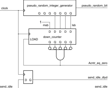
Figure 5-5 shows an example implementation of idle generation logic which meets the requirements.
X-Ref Target - Figure 5-5
Figure 5-5:
Example of a Pseudo-Random Idle Code Group Generator
pseudo_random_integer_generator pseudo_random_bit clock send_idle send_idle send_idle_dlyd Acntr_eq_zero D Q LOAD down_counter Q Q Q Q Q Q Q Q Q Q Q Q D D D D D msb lsb 1
send_K = send_i dl e & (!send_idle_dlyd | send_i dl e_dlyd & ! A cntr_eq_zero & pseudo_random_bit) send_A = send_i dl e & send_idle_dlyd & A cntr_eq_zero
send_R = send_i dl e & send_idle_dlyd & ! A cntr_eq_zero & !pseudo_random_bit
Section 5: PCS and PMA Layers R
5.4.9 Clock Compensation
The Aurora 8B/10B protocol provides a compensating mechanism for clock rate differences between the transmitter and receiver. This mechanism, called clock compensation, can accommodate up to a ± 100 ppm clock rate differential between the transmitter and the receiver. The Aurora 8B/10B protocol implements clock compensation by periodically inserting clock compensation sequences into idle patterns or user data. Clock compensation sequences should not be inserted into user flow control PDUs, see Section 3.1.4 “User Flow Control Operation,” page 22.
The clock compensation sequence consists of six copies of the clock compensation ordered set, /CC/. The clock compensation sequence shall be transmitted at least every 10,000 code groups even when there are PDUs or other code groups available for transmission. For multi-lane channels, the complete clock compensation sequence is transmitted
simultaneously over each lane that makes up the channel.
5.4.10 Single-Lane Transmission Rules
A single-lane channel has a single differential pair in each direction. A single-lane channel shall be encoded and shall transmit the character stream of control ordered sets and PDUs received from the upper layers over the differential pair in the order the characters were received from the upper layers.
When neither control ordered sets nor PDUs are available from the upper layers for transmission, the idle sequence shall be fed to the input of the encoder for encoding and transmission.
On reception, the code group stream is decoded and passed to the upper layers. Figure 5-6, page 39 shows the encoding and transmission order for a channel PDU transmitted over a single-lane channel. The data stream shown in Figure 5-6, page 39 illustrates many of the cases defined in the protocol. The key features to note in the figure are:
• The first example shows how a channel PDU with an odd number of payload octets is padded to maintain alignment of the /ECP/ symbol
• The third example shows a channel PDU interrupted by a clock compensation sequence, and idles
8B/10B Transmission Code
R
X-Ref Target - Figure 5-6
Figure 5-6: Single-Lane Channel Typical Data Flow
/I/ /I/ /I/ /I/ /SCP/1 /SCP/2 /SCP/1 /SCP/2 /SCP/1 /SCP/2 D0 D1 D2 D3 D4 D5 D6 /P/ /ECP/1 /ECP/2 /ECP/1 /ECP/2 /I/ /I/ /I/ /I/ D0 D1 D2 D3 D4 D5 /I/ /I/ D0 D1 D2 D3 /CC/1 /CC/2 /CC/1 /CC/2 /CC/1 /CC/2 /CC/1 /CC/2 /CC/1 /CC/2 /CC/1 /CC/2 D4 D5 D6 D7 /I/ /I/ Time /I/ /I/ D8 D9 D10 D11 D12 /P/ /I/ /I/ /I/ /I/ /I/ /I/ /I/ /I/ /I/ /I/ /I/ /I/ /I/ /I/ /I/ /I/ SP002_03_05_062507 0 1 2 3 4 5 6 7 8 9 10 11 12 13 14 15 16 17 18 19 40 41 42 43 44 45 46 47 48 49 50 51 52 53 54 55 56 57 58 59 60 61 62 63 64 65 66 67 68 69 70 71 72 73 74 75 76 77 78 79 20 21 22 23 24 25 26 27 28 29 30 31 32 33 34 35 36 37 38 39 /SCP/1 = /K28.2/ /SCP/2 = /K27.7/ /CC/1 = /K23.7/ /CC/2 = /K23.7/ /ECP/1 = /K29.7/ /ECP/2 = /K30.7/ Note:
Section 5: PCS and PMA Layers R
5.4.11 Multi-Lane Striping and Transmission Rules
The Aurora 8B/10B protocol defines the striping of user data and control ordered sets across channels consisting of an arbitrary number of lanes. The striping scheme balances lane efficiency and implementation simplicity. Figure 5-7 is an overview of the striping scheme.
Striping allocates symbol-pairs across multiple lanes. Striping is the method used to send data simultaneously across all n lanes of a multi-lane channel. The symbol stream is striped across the lanes on a symbol-pair by symbol-pair basis. Striping may begin in any lane and proceeds lane by lane. For example, the first symbol-pair is striped onto lane 0, the second symbol-pair onto lane 1, and the nth symbol-pair onto lane n-1. The nth+1 symbol-pair is striped onto lane 0.
The only special requirements are as follows:
• The individual symbols in the symbol pairs /SCP/, /ECP/, /SNF/, /SUF/ must not be split between lanes, but can be transmitted and received on any lane
• When /I/ sequences are transmitted, the same data pattern must be transmitted over each lane in the channel that requires an /I/ sequence
Figure 5-8, page 41 shows how the same channel sequence shown in Figure 5-6, page 39 would be transmitted over a channel consisting of three lanes.
X-Ref Target - Figure 5-7
Figure 5-7: Channel Striping Overview
Lane 1 sp002_03_06_110402 D3 D2 /SCP/2 /SCP/1 Lane 0 D1 D0 D3 D2 D5 D4 /SCP/2 /SCP/1 Transmitting Data D1 D0 D3 D2 D5 D4 /SCP/2 /SCP/1 Receiving Data D5 D4 D1 D0
8B/10B Transmission Code
R
X-Ref Target - Figure 5-8
Figure 5-8:
Typical Data Flow for a Triple-Lane Channel
0 1 2 3 4 5 6 7 8 9 10 11 12 13 14 15 16 17 18 19 20 21 22 23 24 25 26 27 28 29 30 31 32 33 34 35 0 1 2 3 4 5 6 7 8 9 10 11 12 13 14 15 16 17 18 19 20 21 22 23 24 25 26 27 28 29 30 31 32 33 34 35 0 1 2 3 4 5 6 7 8 9 10 11 12 13 14 15 16 17 18 19 20 21 22 23 24 25 26 27 28 29 30 31 32 33 34 35 /I/ /I/ /P/ /SCP/1 /CC/1 /CC/2 /CC/1 /CC/2 /CC/1 /CC/2 /CC/1 /CC/2 /CC/1 /CC/2 /ECP/1 /ECP/2 /CC/1 /CC/2 /CC/1 /CC/2 /CC/1 /CC/2 /CC/1 /CC/2 /CC/1 /CC/2 /CC/1 /CC/2 /CC/1 /CC/2 /CC/1 /CC/2 /CC/1 /CC/2 /CC/1 /CC/2 D0 D1 D0 D1 D0 D1 D2 D3 D2 D3 D4 D5 D6 D2 D3 D4 D5 /I/ /I/ /I/ /I/ /I/ /I/ /I/ /I/ /I/ /I/ /I/ /I/ /I/ /I/ /I/ /I/ /I/ /I/ /P/ D4 D5 D6 D7 D8 D9 D10 D11 D12 /SCP/2 /SCP/1 /SCP/2 /ECP/1 /ECP/2 /ECP/1 /ECP/2 Note: SP002_03_07_082614 Time /SCP/1 = /K28.2/ /SCP/2 = /K27.7/ /CC/1 = /K23.7/ /CC/2 = /K23.7/ /ECP/1 = /K29.7/ /ECP/2 = /K30.7/ /CC/1 /CC/2 /CC/1 /CC/2 /I/ /I/ /I/ /I/ /I/ /I/ /I/ /I/ /CC/1 /CC/2 /I/ /I/
Lane 0 Lane 1 Lane 2
/SCP/1 /SCP/2
/I/ /I/