________________________________________________________________________________
The Development and Practical Application
of Close-Fit PE Lining Technologies
Author: Dr John De Rosa, Subterra Systems, United KingdomPaper 2.2
SYNOPSIS
The close-fit lining of mains with polyethylene pipes evolved from conventional PE sliplining as a means of reducing mains leakage and, in the case of water supply mains, ensuring water quality, whilst at the same time maximising the flow capacity of the main after lining. Close-fit PE lining technologies are now available as fully engineered solutions for both structural and interactive applications, and have been used successfully over several decades for water, gas, sewerage and other industrial applications. The paper will present an overview of close-fit PE lining technologies, recent developments, and significant practical applications.
INTRODUCTION
The mature utility pipeline infrastructures in developed countries that were originally constructed from traditional engineering materials such as cast iron, and more recent installations constructed from other materials that have proven unexpectedly prone to corrosion attack, are approaching the ends of their serviceable lives. As they do so, they command an increasing resource, and hence utility budget, for their repair and maintenance in order to deal with the deterioration of pipeline fabric and/or joints, so that the utility provider can keep pace with the demands of its consumers. A point is clearly reached when the utility’s so-called pipeline asset becomes a liability in terms of repair expenditure, and in terms of customer perception of reliability and security of supply. The choice then becomes one between either full replacement, and some form of pipeline rehabilitation. In the urban situation, pipeline replacement can be difficult and expensive, not least due to congestion of existing underground services, which can make it difficult to install a new pipeline at the preferred line and level. It is particularly in this situation where the hole in the ground occupied by an existing pipeline can be the asset of the utility, since it affords a potential underground pathway through which a new pipe or pipe lining can be threaded, with much reduced disturbance to both adjacent utility services, and to the general public.
ORIGINS
The method of inserting a pressure pipe liner into an existing utility pipeline as a means of reducing leakage arising from through-thickness corrosion and/or deteriorated joint seals, is not new. Doubtless many one-off examples could be cited dating back to the dawn of the Industrial Age and beyond, but it has only been with the development and
introduction of polyethylene (PE) as a pipe material in the past 50 years that pipelining has become a widely practiced
and accepted method.
The reason for this is the particular characteristics of PE pipe. PE pipe, certainly in the forms developed for, and used extensively by, the UK gas and water industries over the past 30 years, is flexible, very tough and can be joined by fusion welding methods to form effectively monolithic pipeline strings of almost any desired length.
The simplest form of pipelining using PE pipe is sliplining. In this method, the PE pipe outside diameter is chosen to be significantly less than the minimum internal diameter of the existing pipeline to be lined, to aid insertion. After the host pipe bore has been suitably cleaned and any protruding obstructions have been removed, a prepared string of PE pipe of the appropriate length is simply pulled into place. Since standard sized, fully structural PE liner pipe is used for this application, connections and branches etc to the new PE pipeline can be made using standard PE pipeline fittings at preselected positions where the existing host pipe is broken out locally to expose the PE slipliner pipe.
The key disadvantage of the sliplining process is that the use of an undersized PE liner pipe can significantly reduce the cross sectional area, and hence the flow capacity, of the existing pipeline, which may be a critical parameter for the pipeline owner. It is this limitation of the simple sliplining process that stimulated the development of close-fit PE pipe lining systems for pressure (and indeed non-pressure) pipeline applications.
CLOSE-FIT PE PIPE LINING SYSTEMS FOR PRESSURE PIPES
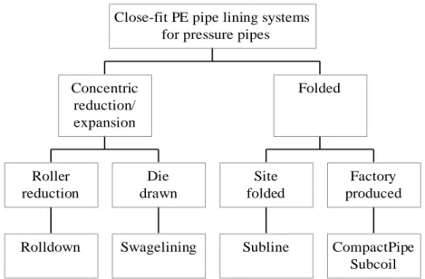
The versatility of PE as a pressure pipe material has spawned the development of a wide range of innovative close-fit pipe lining systems that take advantage of the unique combination of properties of this commodity material. Whilst there is a wide range of proprietary close-fit PE pipe lining systems available on the market for lining pressure pipes, these can all essentially be classified under one or other of two generic system types, i.e.
Concentric reduction/expansion liners Folded liners.
These systems are summarised below in Figure1, and are described in more detail in the following sections. All of these systems are well established, fully engineered technologies that already have a long track record of successful use and service in a range of varied applications, including drinking water, gas sewerage and industrial applications.
CONCENTRIC REDUCTION/EXPANSION PE LINER SYSTEMS
As a family, these close-fit liner installation techniques involve the on-site processing of the PE liner pipe prior to installation. In these methods, the original diameter of the PE liner pipe is chosen to be slightly larger than the bore of the host pipe into which it is to be inserted. The processing technique is then used to reduce the outside diameter of the PE liner pipe to less than the minimum bore diameter of the prepared host pipeline section. The outside diameter of the reduced liner is maintained either with or without the application of longitudinal tension (this requirement depending on the specific processing system being used). The PE liner pipe, in its reduced diameter state, is then inserted into the host pipe, as for sliplining. Once in place, the liner is reverted to a close fit with the host main, either by releasing the longitudinal tension and/or by hydraulic pressurisation. These techniques are normally applied to relatively thick-walled (i.e. structural) PE pipes (e.g. SDR 11 – 26, depending on diameter), owing to the relatively high processing forces they impose on the pipe. The PE liner pipes themselves are manufactured from well-established grades of PE resins that already have in-country approvals for the relevant application (e.g. drinking water supply, gas distribution).
________________________________________________________________________________
Figure 1 – Classification of close-fit PE pipe lining systemsThe concentric reduction/expansion liner group of techniques can be further subdivided into two categories, i.e. the roller reduction systems (e.g. Rolldown) and the die drawn systems (e.g. Swagelining).
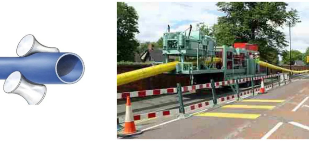
In the Rolldown system (see Figure 2), a prepared string of oversized PE pipe is pushed through a roller box processing unit at ambient temperature to produce the reduced diameter liner pipe. The reduced outside diameter obtained after Rolldown processing is typically about 10% less than that of the original PE pipe. Once processed through the Rolldown machine, the reduced diameter of the PE liner pipe is maintained without the need to apply axial tension to the pipe string. This means that, if there are space constraints around the work site e.g. in busy roads, urban centres etc., it is possible to Rolldown the PE liner pipe string in advance at a convenient site remote from the installation site. The prepared liner pipe can then be towed to the insertion point at a time chosen to cause minimum disruption to traffic and/or commercial activity. Once at the insertion point, the Rolled down liner pipe is inserted into the host main as for a conventional slipliner installation. The liner pipe ends are then sealed and the liner is reverted to form a close fit with the host pipe by hydraulic pressurisation. The Rolldown process is capable of processing PE liner pipes in the size range 100mm to 500mm diameter, with SDRs ranging from 11 to 26, depending on the actual liner pipe diameter. Rolldown Roller reduction Swagelining Die drawn Concentric reduction/ expansion Subline Site folded CompactPipe Subcoil Factory produced Folded
Close-fit PE pipe lining systems for pressure pipes
(a) Rolldown process (schematic) (b) Rolldown of 450 SDR 21 PE-80 pipe
Figure 2 – Rolldown on-site concentric PE liner pipe reduction process
In the die drawn lining systems (see Figure 3), a string of oversized PE liner pipe is pulled through the processing unit under tension at ambient temperature to reduce its diameter, and is then directly winched into the prepared host pipe, with the axial tension having to be maintained until the liner is fully inserted to ensure the reduced diameter is held. The axial tension is then released and the liner is allowed to revert naturally to a close fit with the host pipe. The Swagelining process utilises a simple ring die arrangement, and is available for sizes from 75mm to 1200mm diameter. The Swagelining of larger diameter liner pipes requires the application of particularly high axial tension forces to the liner pipe, which can pose safety issues when using cable winches in busy urban areas. The use of pipe bursting machines as pipe pullers can reduce this risk. However, it is also necessary to consider the magnitude of the pulling forces required to process the liner pipe through the machine, which in turn may necessitate the construction of thrust walls at the face of the insertion trench to dissipate the loads involved.
(a) Die drawing (schematic) (b) Static ring die reduction (Swagelining)
Figure 3 - Die drawn concentric reduction process
The PE pipes used for concentric reduction close-fit installation processes typically have to be thick-walled in order to withstand the stresses during processing. Consequently, such liners are normally fully structural, i.e. are capable of withstanding the pipeline operating pressures without additional external hoop support from the host pipe. This in
________________________________________________________________________________
turn means that liner pipe end terminations and customer service connections can generally be made using existing PE pipeline fittings, albeit with some minor adjustments where necessary to resize the liner pipe ends to fit standard size products (see below).FOLDED PE LINER SYSTEMS
The underlying principle of folded liner pipe systems is to start with a liner pipe that has a diameter (strictly, a circumference) slightly less than the minimum bore diameter of the host pipeline to be lined. This is to ensure that the liner opens fully on reversion, so as to avoid the formation of longitudinal folds of surplus material that would otherwise be obtained. The liner pipe is folded into the characteristic “U” or “C” shape to reduce both its overall width and cross sectional area, in order to aid insertion. This folding process may be done either hot (exclusively for factory-produced folded liners) or cold (either in the factory or on site), depending on the specific technique. The shape of hot-folded liners is maintained without any additional constraint, whilst the shape of cold-folded liners normally has to be restrained using temporary strapping or sheathing.
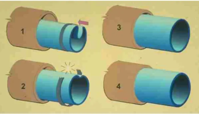
The folded liner is then sliplined into the prepared host pipe, the ends are locally re-rounded, and the liner is reverted to a round section and close fit with the host pipe. Cold-folded liners (both site- and factory-folded) are generally reverted by hydraulic pressurisation using cold water. Hot-folded liners are reverted using a combination of heat (typically steam) and air pressure.
In Subterra’s site-folding process, Subline, strings of PE liner pipe are pushed through a trough-and plough forming unit at ambient temperature to produce the characteristic heart shaped cross section (see Figure 4). This shape is then maintained by securing the folded liner at specified intervals with suitable temporary strapping. The processed liner pipe is fully inserted into the prepared host pipe, the ends are locally re-rounded, and end termination fittings with closure (blanking) plates are fitted. The liner is then gradually pressurised with cold water (typically to 1-2 bar) to break the temporary strapping, and is then further pressurised to revert the liner to a round profile and a close fit with the host pipe.
(a) Cold forming of liner pipe (b) Lining process (schematic)
Figure 4 – Subline on-site PE liner pipe cold-folding process
Cold folding generally limits the use of Subline to relatively thin-walled PE liner pipes (i.e. SDR 26 and greater (thinner)), which are therefore typically designed as interactive liners. As is the case for Rolldown, the PE liner pipes used in the Subline process are themselves manufactured from well-established grades of PE resins that already have in-country approvals for the relevant application (e.g. drinking water supply, gas distribution). Subline has been used to process PE liner pipe ranging in diameter from 75mm up to 1500mm. Fully-engineered specialist liner end
terminations that ensure the thin-walled PE liner pipe is fully supported against the internal pipeline pressure over its entire length are commercially available to complete the lining system (see below).
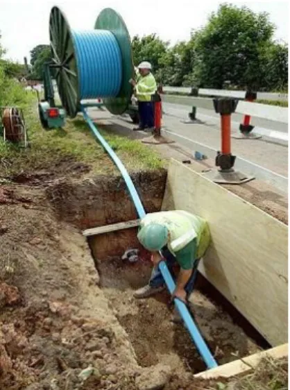
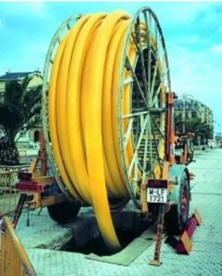
This on-site cold-folding/cold reversion technology has subsequently been adapted by Subterra to develop its factory-folded liner system, Subcoil (see Figure 5). The PE liner pipe is extruded and cooled to ambient temperature in its circular shape prior to cold folding in an in-line processing unit. The folded liner shape is then restrained either by co-extruded sheathing or taping, prior to coiling on drums. The product is then taken to site and installed essentially in the same way as for the site-folded liner systems described above. Subcoil is available in sizes from 3”(75mm) to 9” (225mm) nominal and in SDRs from 26 to 41, depending on application. For water applications, the 3”, 4” and 6” Subcoil product is available as a structural, stand-alone SDR 26 PE liner pipe, having a design pressure rating of 6 bar. A fully-developed and proven range of liner end terminations and service pipe connections is available to complement the Subcoil system for both structural (i.e. stand-alone) and interactive lining applications (see below).
(a) Subcoil – factory-folded PE liner pipe with retaining sheath
(b) Subcoil installation
Figure 5 – Subcoil factory cold-folded PE liner pipe
Hot-folded PE liner pipes are produced exclusively in a factory environment. The product is extruded as round pipe and then immediately folded to the desired cross section, after which it is wound onto drums for transport to site. At the works site, the product is taken directly from the drum and inserted into the prepared host pipeline. The protruding pipeline ends are locally rerounded to permit the fitting of end closures. Steam is then passed along the length of the liner to warm it to the correct temperature for reversion, which is carried out by controlled pressurisation with air. This opens the liner to a circular profile and presses it against the host pipe wall. The steam injection is then discontinued and the liner allowed to cool under pressure in order to maintain the close fit. Such liners are available in sizes from 100mm to 500mm diameter, with SDRs from 17 to 32 depending on size (see Figure 6).
________________________________________________________________________________
(a) Factory hot-folded PE liner pipeafter insertion (top) and reversion (bottom)
(b) Factory hot-folded PE liner pipe - insertion on site
Figure 6 – CompactPipe - factory hot-folded PE liner pipe
CLOSE-FIT PE LINER PIPE END TERMINATIONS AND CONNECTIONS
In order to be able to turn a method of installing a close-fit PE liner pipe into a practically-viable close-fit pipe lining system, it is necessary to be able to connect the liner pipe to other parts of the pipeline system, including adjacent sections of main (lined or unlined) and customer service pipe connections. In particular, it is not only necessary to be able to do this at the time of the liner installation (sometimes referred to, for convenience, as “prefit” connections), but also, with equal facility, after the lined main has been commissioned and is service (“retrofit” connections). One of the key issues associated with close-fit liners in this respect, is that, by definition, they will normally be a non-standard size after installation. This is because the actual host pipe bore of a pipeline of any given nominal size, material and pressure class will have a manufacturing tolerance. This pipe bore variability is further exacerbated when considering different pipe materials of the same notional size and class, e.g. vertically (pit) cast iron, centrifugally (spun) cast iron and ductile iron. The finished external diameter of an installed close-fit liner is therefore governed by the actual size of the existing host pipe, and cannot even be relied upon to be a standard size in those host pipe cut-out sections where structural liners emerge from the confines of the existing pipeline.
One significant advantage of polyethylene as a pipeline material is that it can be expanded mechanically by up to 10% without impairing its long-term serviceability in terms of pressure capability.
Turning first to the case of independent (i.e. fully-structural) close-fit PE liners, this feature of PE means that such liners can be terminated beyond the end of the host pipe and the ends expanded to suit the next available standard size of conventional fittings (where this is within the 10% PE pipe expansion limit). This locally-expanded liner outside diameter is invariably maintained by then fitting an insert stiffener of an appropriate material, both to ensure dimensional stability and tolerance for jointing and, in the case of elastomerically-sealed mechanical joints, to resist collapse under the seal compression pressures. This insert may be part of a conventional mechanical fitting (e.g. the spigotted flange of a Viking Johnson Aquagrip fitting or similar), or it may be a bespoke fabrication, e.g. stainless steel insert ring for use in conjunction with standard size electrofusion couplers.
(a) EF coupler with insert stiffener (b) Aquagrip fitting
Figure 7 – Independent close-fit liner end termination solutions
Customer service connections to independent (structural) close-fit PE liner pipes are made by exposing a section of the liner pipe, as for conventional sliplining. As noted previously, the outside diameter of the liner pipe at such points cannot be determined accurately in advance. Fortunately, various PE electrofusion saddle options are now available that have been developed specifically as diameter “range-rated” products, and have been fully type approved for use on a range of different conventional PE pipe nominal sizes. By interpolation, such fittings are available for use on independent close-fit PE liners. Where the outside diameter of the installed liner pipe is fixed (e.g. structural Subcoil), bespoke service connection solutions are commercially available.
(a) Range-rated EF service connection tees on concentrically-reduced PE pipe
(b) Structural Subcoil EF connection tee
Figure 8 – EF service tees for independent close-fit PE liners
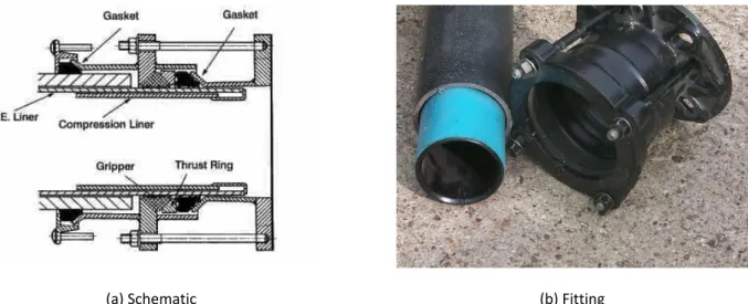
Additional considerations apply for interactive close-fit PE liner pipes. Since these, by definition, are unable to sustain the internal mains operating pressure without the long-term hoop support of the existing host pipeline, they must be supported fully over their entire length, including where they emerge from the constraints of the host pipe, where this is applicable. In the Viking Johnson LinerGrip fitting, the PE liner pipe is terminated beyond the end of the host pipe, and an insert stiffener is used to support the thin-walled liner at the correct external diameter. The LinerGrip fitting is then installed onto the exposed liner end and compressed onto it, forming both a pressure-tight seal and a grip capable of withstanding any axial contraction forces of the PE liner pipe in service. Other methods involve terminating the liner inside the host pipe (or a surrogate extension) and forming a compression seal, either by compressing the liner into a series of grooves on the bore of the pipe-end fitting (QA Weld Tech in-line compression fitting for PE lined pipe), or by bridging between the liner end and the host pipe bore immediately adjacent with an internal
________________________________________________________________________________
(compression) seal (e.g. AMEX-10). Adjoining sections of lined pipe terminated using these methods can then be connected together using a variety of conventional methods, including slip couplings (e.g. for cast iron host pipelines) and welding (for steel host pipelines).(a) Schematic (b) Fitting
Figure 9 – LinerGrip end termination for structural and interactive PE liner applications
Customer service connections to interactive close-fit, thin-walled PE liners have to be made using specialist fittings. These typically involve clamping and compressing the PE liner wall between two faces of a fitting that is secured in the host pipe wall (see Figure 10).
Finally, some, but not all, of the end connection and customer service connection technologies outlined above clearly lend themselves equally well to retrofit installation onto live mains. This is most particularly the case for independent (structural) solid-wall PE liners, since these are in essence stand-alone pressure pipes once installed, and therefore can be worked on as such, subject to the previous caveats. With some notable exceptions, retrofit installation of end terminations (e.g. for cutting in new pipeline branches) and customer service connections onto interactive PE liner pipe systems requires the lined pipeline to be decommissioned.
(a) Schematic (b) Fitting details
PRACTICAL EXPERIENCE
Close-fit PE lining technologies are now well-established, mature and technically proven methods for pipeline rehabilitation. They have been used extensively, both in the UK and overseas, for applications ranging from drinking water, gas, sewerage and industrial pipelines. In this respect, Subterra’s various close-fit PE lining technologies have been used to install some 750km of liner pipes, including 400km Rolldown, 225km Subline and 120km Subcoil. The following paragraphs highlight a selection of key projects for ach of these technologies.
Rolldown
Twin 12” cast iron sludge pumping main upgrade – A4 Bath Road, Heathrow, London
As part of the development of Terminal 5 at London’s busy Heathrow Airport, Thames Water had to close down its Perry Oaks sewage sludge dewatering plant which occupied part of the proposed site. The Perry Oaks works, the largest of its type in Britain at that time, handled some 20,000m3 of sewage sludge per week. This was delivered to Perry Oaks from the Mogden sewage treatment works near Twickenham via a twin 12” cast iron pipeline. The plan was to re-route the flows to Thames Water’s Iver South facility, which in turn required the upgrading of the Mogden pumping plant and the sludge transport mains. The main contractor for these works was Costain. Part of the sludge mains upgrade works involved the refurbishment of some 4km of twin 12” cast iron pipeline that was laid approximately 3 metres beneath the nearside lane of the westbound A4 trunk road between Cranford Bridge and the BAA Compass Centre on the northern perimeter of the airport. This road is a Red Route into London, and one of the main feeders to Heathrow Airport from the West via the M25 Motorway. The mains also crossed the road in several locations to compensate for the curvature of the road.
It was immediately obvious that open-cut replacement of the mains would be unacceptable, other than as a method of last resort, owing to the huge impact such works would have had on traffic flows to and from, and around, the airport. Both pipebursting and horizontal directional drilling for the installation of new pipes were ruled out on the basis of the density of other services in the area and the risks these methods would pose to them. Conventional sliplining was considered, but rejected because of the loss of flow cross section, and the impact this would have had on sludge pumping costs. Close-fit lining with a structural PE liner pipe was identified as a suitable solution, given the constraints, and Subterra’s Rolldown technique was chosen as the preferred method.
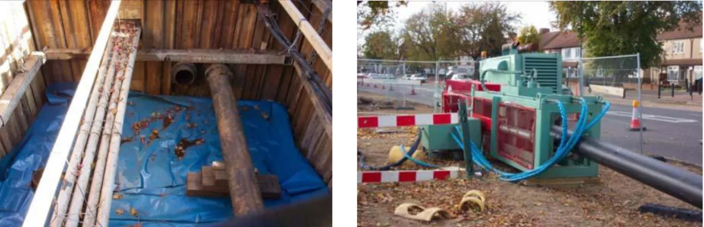
Following the initial site investigation, a programme plan was drawn up to line each main in 12 section lengths ranging from100 to 690 metres. There were a number of crossover and air valve chambers along the length of the sludge mains that provided access to the buried pipelines. These chambers were located at approximately 1 km intervals along the mains. Access pits were therefore planned at positions approximately halfway between these chambers along the route such that the Rolldown liners could be inserted via the temporary excavated pits and winched into place from the existing crossover and air-valve chambers. The insertion pits were constructed with sufficient width to permit work to be carried out on both mains (see Figure 11). Using both the existing and new crossovers it was possible to follow a sequence of lining that involved replacing parallel sections of main one after the other from the enlarged access pits, whilst maintaining the flow of sludge at all times. The planned duration for the works was 37 weeks, with a stand down period of 7 weeks in the summer of 2004. This was to allow the sludge to flow down both mains to accommodate for the increased capacity during the peak season. A comprehensive traffic management plan was also developed and agreed in consultation with the Highways Agency, Traffic for London, Heathrow Airport Authority, Local Councils and other interested parties to minimize any disruption caused by proposed Rolldown works.
________________________________________________________________________________
(a) Rolldown insertion pit (b) Rolldown machine
Figure 11 - Mogden-Perry Oaks 12” sludge pumping main upgrade
Pipe delivery was programmed to occur during off-peak traffic hours, and a lay down area was designated adjacent to each of the insertion pits. The pipes were then butt fusion welded within a secured easement to form a pipe string equivalent in length to the replacement section. The section of main to be lined was decommissioned and cleaned by drag scraping, followed by a CCTV survey to ensure that no protrusions or obstructions were present prior to the liner being inserted. The Rolldown machine was positioned adjacent to the insertion pit, and the pipe string was pushed through the machine, reducing the liner diameter by approximately 10%. The liner was then simply inserted into the host main using a hydraulic winch. On completion, the liner ends were mechanically re-rounded to enable the fitting of end couplings. Blank flange plates were fitted and the liner reverted towards its original diameter by pressurizing with water. After the liner as fully reverted, the lined main was put into commission and the parallel main was decommissioned and lined. This sequence of installation was repeated throughout the length of the contract. The Rolldown lining works were completed in November 2004 within budget and in accordance with the programme included in the pre construction plan.
The Perry Oaks Rolldown project subsequently received the 2005 UKSTT Award for Renovation in the Large Project category.
12” cast iron gas main – Grosvenor Bridge, Chester
National Grid was engaged in the replacement and upsizing of the entire medium pressure gas mains network in Chester with new PE pipe, for which the main contractor was May Gurney. As part of this programme, it was necessary connect a new PE main running north along the A483 to the city centre, which involved traversing the steep-sided River Dee valley on the south side of the city. The existing gas supply main, a 12” cast iron pipeline, had been laid in the deck of the historic Grosvenor Bridge across the River Dee (see Figure 12), which is the main traffic artery from the southern orbital bypass into the centre of Chester. The main span of the bridge, some 70 metres long, and its unusual height (approx 20 metres), plus the proximity of a high pressure gas main crossing under the river in the vicinity and the adjacent elevations, all meant that directional drilling a new pipeline across the valley was not a practical option, owing to the long approach lengths that would have been required to accommodate the angles needed for pipeline insertion. Pipebursting was rejected due to the relatively shallow cover and, more importantly, fears of disturbing the fabric of the historic bridge. Open cut replacement was considered inappropriate due to the highly adverse effect this would have had on traffic flows to and from the city centre. It too was ruled out effectively due to concerns over the effect of such disruptive works on the bridge structure.
(a) Grosvenor Bridge (b) Rolldown in progress Figure 12 - Rolldown PE close-fit lining of 12” gas main in Grosvenor Bridge, Chester
After having considered the available options, May Gurney decided that the best option would be to make use of the existing cast 12” iron main in the bridge deck, and to install a close-fitting PE liner pipe using Subterra’s patented Rolldown process. This would provide sufficient supply capacity whilst at the same time both minimising the risks of structural damage to the historic bridge structure and limiting disruption to traffic on the main approach into Chester from the South.
To execute the works, launch pits some 200 metres apart were dug either side of the bridge to expose the decommissioned pipeline. These were located so that obstruction to the traffic was kept to a minimum (see Figure 12). The main was then cleaned and inspected prior to the Subline processing and insertion of the 315mm OD SDR 26 PE-80 liner pipe. The lining was carried out in two sections of 75m and 125m respectively, the cleaning, inspection and liner insertion operations being achieved in a single day. The whole works, from the first cut to the road surface to its final reinstatement, was completed in 7 consecutive days, which had been scheduled to cause the minimum possible traffic disruption. The whole process was much quicker than conventional open cut installation. This use of trenchless technology also resulted in a solution that was cheaper than the other alternatives of either submerging a pipeline under the river, or installation by directional drilling, owing to the technical constraints and topographical challenges of the particular location.
May Gurney’s project, including the Rolldown close-fit PE lining of the 12” gas main in the historic Grosvenor Bridge, subsequently received the UKSTT’s 2007 Award for Renovation in the Small Projects category.
SUBLINE
Eccup 42” diameter ferroconcrete raw water main refurbishment
As part of the programme of works associated with the construction of a new water treatment plant at their Headingly works, Yorkshire Water needed to resolve an ongoing problem of joint leakage on an 820 metre section of 42” ferroconcrete pipeline that feeds raw water to the works from the Eccup reservoir.
The pipeline route started adjacent to an access road to a major local cricket ground and training pitch for Yorkshire Cricket Club. From there, it crosses the busy northern section of the Leeds A6120 ring road via a series of 11¼o and 22½o bends. The 42” line is then joined by two large aqueducts laid parallel in close proximity to one another, and together, the three pipelines follow a route, up to 4.5 metres deep in places, below a narrow track which weaves its way through a major public park comprising mature woodland supporting a wide variety of wildlife. Vehicular access
________________________________________________________________________________
to the park was via an ornate stone gateway that put severe restrictions on vehicle height and width. In addition to these features, there was a washout branch located directly under the ring road that had to remain connected, and a number of other pipeline fittings, the removal of which posed a threat to the stability of the three parallel pipelines. This, the need to minimise the impact of the pipeline refurbishment works on the local environment and on traffic flows on a major road, and the fact that time was of the essence, meant that new construction was not an attractive option.The main contractor, Earth Tech Morrison, therefore consulted Subterra on the feasibility of lining the main using the Subline process. A conventional approach to Subline liner installation was quickly ruled out, particularly on the basis of the difficulties of vehicular access into the public park. Also, it would not have been possible to have inserted the whole 827m of liner pipe in a single pull, owing to the friction associated with the weight of the liner, and the additional resistance that would be expected in negotiating the 10 bends and numerous pulled joints along the length of the pipeline in question.
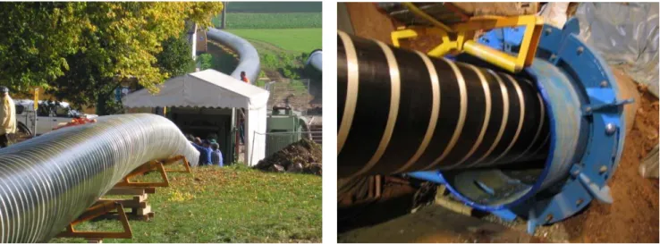
(a) Subline processing of PE liner pipe string (b) Subline insertion Figure 13 – Subline PE lining of 42” diameter ferroconcrete raw water main, Eccup
An innovative approach was finally adopted in which a single liner insertion pit was excavated in the lane outside the cricket ground, together with three small winch/reception pits, these being located at the end of the section to be lined in the park and at two other strategic points along the pipeline route. The pipeline was then decommissioned and broken open. Tree root masses intruding at the pipeline joints were removed manually, and the main was subsequently cleaned using brush pigs. The liner pipe, 1050mmOD SDR 58 MDPE, was butt fused into strings in a field 200m remote from the insertion point and brought to the Subline machine, which was positioned next to the insertion pit. Here the liner pipe was formed and inserted into the main. The first section, some 147 metres long and weighing 9 tonnes, was then pulled from the insertion pit, past the two intermediate pits, until it arrived in the winch pit in the park. The second and third liner lengths, respectively 327m (20 tonnes) and 351m (22 tonnes) were similarly fused into strings, formed and inserted from the same insertion pit to the successively nearer winch pits. Once in place, the liner ends were locally re-rounded, the three liner sections were pieced together, and the entire 827 metre length was reverted to a close fit by hydraulic pressurisation in a single operation
Finally, the washout branch located under the Leeds ring road was reinstated by manually cutting the liner back either side of the connection, securing the liner ends to the host pipe each side of the branch, and then fitting AMEX-10 seals to bridge from the inside of the liner pipe to the bore of the exposed main. The lined main was successfully re-commissioned on time and within budget, having caused the smallest possible environmental impact and zero disruption to traffic on the busy main road. This project was the recipient of the UKSTT’s 2003 award in the Large Renovation Project category.
Halzhausen 1500mm diameter prestressed concrete bulk water supply pipeline
Zweckverband Landeswasserversorgung (LW) is one of the largest bulk water suppliers in Germany. They provide potable water to over 3 million inhabitants in 250 towns and cities in Baden-Württemberg and Bavaria. Over many years they have battled with a major leakage problem on one of their main trunk supply pipelines south east of Stuttgart. The pipeline was constructed from 1500mm diameter prestressed concrete with joints at every 5 metres sealed using rubber gaskets. Two sections of this pipeline, with a total length of 6.7 kilometres, were experiencing leakage of up to 35 litres per second (3 Megalitres per day). An investigation had revealed that, whilst the pipeline fabric was generally in a structurally sound condition, the leakage was a result of degradation of the rubber sealing gaskets in many of the joints.
The pipeline forms a strategically vital link in the LW network and, based on available storage capacity, could only be taken out of service for a maximum of three days. As consequence of this, previous repairs had been limited to installing internal seals on individual joints by man entry during routine maintenance shutdowns. However, this had proved both time consuming and costly as only a small number of these seals could be installed within the short service outage time permitted. A feasibility study of other potential pipeline rehabilitation options undertaken by LW engineers identified Subline as a potential solution for this problem, which would solve the ongoing joint failure and leakage for good. It was decided that a trial of the Subline system would be undertaken by Subterra’s German licensee, Pfeiffer, on a 538 metre section of the pipeline located in rural countryside close to the town of Halzhausen. The section of pipeline chosen for the trial was particularly challenging in that it formed a long sweeping curve that turned through approximately 90o within its 538 metres length (R ~ 230 D), and had to be lined in a single length. The very short time window available in which to install the liner pipe required a pre-project possession and shutdown of the main, in order to prepare the section of main for liner insertion. Some four weeks in advance of the planned liner pipe installation, pits were dug at the selected liner insertion and reception points along the main, some 530 metres apart. The main was then drained down and sections approximately 15 metres long were cut from the pipeline in each pit. Specially designed and fabricated steel flange adaptors were fitted to each of the cut ends. The cut sections of main were then reconnected using steel spool pieces, and the pipeline was recharged and returned to service.
(a) Subline processing of PE liner pipe string (b) Subline insertion
Figure 14 – Subline PE lining of 1500mm diameter prestressed concrete drinking water main, Halzhausen, Germany The liner pipe selected for this project was a 1480mm OD SDR 61 PE-100 pipe. Owing to the space available at the site, it was possible to butt fuse almost the length required as a single string, weighing some 54 tonnes, in advance of the
________________________________________________________________________________
works (see Figure 14). This was then pressure tested and prechlorinated before being processed through the Subline machine ready for insertion. Once the liner was ready, the main was shut down and drained, and the steel spool pieces were removed. The existing internal seals were removed and then Subline liner was towed into the main using a rod pipe bursting machine to supply the tractive force, instead of a conventional wire rope winch. Liner insertion took 6½ hours, after which the liner ends were rerounded and the liner end terminations were fitted. After fitting end plate closures, the liner was filled with water and pressurised to revert it to its original round profile. Once complete, the lined section was pieced back into the existing pipeline and successfully recommissioned well within the permitted 72 hours.The client was delighted with the outcome of the project, which met all key expectations. The timely installation of the liner ensured that the bulk supply reserves to the receiving communities did not fall below the critical level that would have triggered rationing and other emergency measures. In addition, ongoing leakage losses from this section have been eliminated, and with it, the requirement for repetitive leakage detection and local repair involving mains shutdown and local internal sealing. At the time, this was the largest diameter close-fit PE liner pipe installed in the World. Pfeiffer have since installed two further liners of this size, one in Dresden (250m) and a further section on the Halzhausen pipeline (800m)
SUBCOIL
Venford Reservoir to Paignton 9”cast iron main rehabilitation
The 9” cast iron pipeline that supplies water from the Venford Reservoir to Paignton in Devon is a strategic link in South West Water’s mains network. Laid over 70 years ago, the unlined cast iron pipe had suffered heavy internal corrosion due to the soft water it conveys. This in turn had led to the formation of voluminous internal corrosion deposits (tuberculation) in the pipe bore which had significantly reduced the carrying capacity of the pipeline. In addition, the original lead-run joints had also begun to fail resulting in significant leakage from the main, this further impacting on the reduced delivery capacity of the pipeline and increasing maintenance costs.
The Venford pipeline is located predominantly in a rural area of Devon. Its 26km route crosses the Dartmoor National Park and other moorland, and its track is associated with narrow lanes and passes through numerous officially-designated Sites of Special Scientific Interest (SSSIs). The remoteness some of the locations in which the pipeline is laid, and the sensitivity of the environment along much of its length, meant that conventional open-cut replacement was discounted on the grounds of both cost and difficulties of access for the heavy plant involved, which in turn would have caused serious disruption to the road network in the area. Epoxy resin spray lining was discounted as an option because this method could not guarantee long-term sealing of any leaking joints. Sliplining was also rejected this would have reduced the capacity of the main unacceptable. Pipe bursting was considered, but was considered problematic owing to the relatively limited reach of the technique at that time.
As part of the options review, South West Water contacted Subterra to determine the suitability of Subcoil for the proposed application. The Subcoil product supplied for lining 9” mains is a 220mm OD SDR 41 MDPE/PE-80 liner pipe. It is supplied on drums having a capacity of 400metres of 9” Subcoil, which meant that the number of excavations required along the pipeline route could be kept to an absolute minimum. For use, the drum of Subcoil is mounted on a dedicated trailer which has a very compact footprint. This would make it easy to transport it to remote worksites, and to manoeuvre it into position to dispense the product in the narrow lanes. The one remaining issue was the operating pressure of the main. This reached a maximum of 23.8 bar, whereas the Subcoil product only had a stand-alone pressure capability of 3.2 bar. Condition assessment of the cast iron pipeline indicated that it was generally in sound condition with sufficient remaining wall thickness to withstand the operating pressure over the expected life of the refurbished main. Using the interactive liner design principles developed by the University of Bradford for the UK Water Industry and used by Subterra for the design of thin-walled PE liner pipes, it was shown that the SDR 41 PE-80 liner pipe would be capable of spanning joint gap widths (and corrosion hole diameters) of up to 25mm for 50 years at the design pressure, which met the requirements for the project.
(a) Internal corrosion of 9” cast iron main (b) Subcoil insertion Figure 15 – Subcoil PE lining of 9” diameter cast iron water main, Venford Reservoir to Paignton
South West Water approved the use of Subcoil for this application and work commenced. Excavations were dug at selected points along the main for liner insertion and reception pits. Prior to lining, the main was cleaned by drag scraping to remove the corrosion tuberculation. The prepared length was then inspected by CCTV to ensure that there were no protrusions into the pipe bore that might damage the liner during insertion. A line was then passed through the prepared main so that the winch wire could be attached to a special towing nose fitted to the leading end of the liner pie. The liner pipe was then carefully inserted and towed into place, all the time monitoring the winch load to ensure that the tensile limit for the liner pipe was not exceeded. The liner ends were then rerounded and LinerGrip end terminations fitted. The liner was then filled with water and pressurised to burst the strapping tapes and to reform the liner into its round shape and a close fit with the host pipe wall.
Jersey Gas 4” steel pipeline refurbishment
Jersey Gas Company manufactures and distributes an LPG/air mixture mains gas through a network comprising 295 km of PE, cast iron, ductile iron and steel mains serving approximately 10,000 gas consumers. In the mid 20th century, the Company substantially extended the gas distribution network to supply the mainly rural eastern Parishes of the island. To minimise cost, the new network was of welded steel and ductile iron construction, using bitumen-coated pipe of predominately 150 mm and 100 mm nominal bore. In recent years, these mains have begun to show signs of through-wall corrosion. Where these are uneconomic or unsafe to repair, they are conventionally replaced with MDPE as part of an ongoing metallic mains replacement policy.
The majority of these steel and ductile iron mains are in rural areas with narrow roads and low housing density. The potential re-liquefaction of LPG limits the maximum system operating pressure, and the year-on-year increase in diurnal demand means that the network cannot sustain a loss of capacity or an increase in pressure differentials. These factors, coupled with the need to achieve cost effective solutions, limited the choice of mains replacement methods and led directly to the consideration of the Subcoil folded thin-walled PE liner system as the preferred method. This technique appeared to offer an ideal ‘all-round’ solution, requiring minimal excavation and with little or no loss of system capacity. This option also had a small site footprint, which was important in the narrow roads and lanes in Jersey, and also allowed access to premises to be maintained at all times.
A 1040 metre section of 100 mm nominal bore steel main was selected for the close fit lining. The section of main chosen had a history of corrosion, leakage and water ingress. It was originally laid in a trench cut through granite rock that acted as a channel for surface water drainage and, as a result of constant exposure to wet conditions, the main had suffered accelerated corrosion. The pipeline itself was laid in a narrow lane on a bus route with moderately busy traffic. Conventional open cut replacement would have been expected to take some 14 weeks, forcing protracted lane closures and traffic disruption.
________________________________________________________________________________
(a) Subcoil gas liner preparation for insertion (b) Subcoil gas EF customer service teesFigure 16 – Subcoil PE lining of 4” diameter steel gas main, Jersey,
The Subcoil liner pipe was shipped to Jersey on a single drum. The liner installation was tackled in two sections of 600 metres and 440 metres length respectively. Including the gas service connections, the refurbishment was completed with only 9 small excavations by pulling the liner pipe through cut-outs at the service locations. Once the liner had been inserted, a pressure tapping was fitted to one of the exposed liner pipe ends, which were then both sealed using conventional squeeze-off tools. The liner was reverted by pressurising it to a maximum of 2 bar with compressed air, which burst the sheathing and re-rounded the liner inside the host pipe. Finally, the liner end connections and customer service connections were completed using the bespoke EF Subcoil gas system fittings. For the period of gas supply interruption, existing gas consumers served by the main were provided with alternative means of cooking and heating.
The entire project was completed within 18 days, including the permanent reinstatement of excavations, at an outturn cost of €54,000 (£38,296). This figure included recovery of all one-off costs such as development, type approvals and training, and was £50,000 less than the forecast cost for conventional open cut replacement.
SUMMARY
1. Close fit PE liner pipe systems are mature, established technologies, and have been extensively used in a wide range of applications, including water and gas supply, sewerage and industrial applications.
2. Close fit PE liner pipe systems fall essentially into one of two categories, namely, Concentric reduced/expanded liners
Folded liners
Each of these technologies has its individual characteristics and ranges of applications, as indicated in the paper.