A Software Tool to Enable Setting up Network
and System Configurations
Jennifer Poole
Computer Science with Mathematics
2006/2007
The candidate confirms that the work submitted is their own and the appropriate credit has been given where reference has been made to the work of others.
I understand that failure to attribute material which is obtained from another source may be considered as plagiarism.
Summary
The purpose of this project is to design and produce a software tool for use by BAE Systems, a widely known defence company. The tool is to be used by the SAINTT team (Systems Analysis and Integration Technology).
The team need to be able to set their computers up to imitate already existing systems that are used on ships, created by BAE Systems. The reason for this is that the SAINTT equipment is used to test how different systems integrate and communicate with each other, as well as testing certain parts of each system themselves. Each system that the team needs to be able to imitate will be referred to as ‘interfaces’ from now on.
The team currently use a configuration file which states the various details that must be set up. This configuration file is run upon start up and sets up any ports or IP addresses specified. At the moment, the team have to manually alter this configuration file in order to get the correct details set up. When carrying out my placement with the team, I experienced first hand how irritating and tedious this could be and when I mentioned I needed a project for my final year, it was agreed that a tool that could be used to set the computers up would be very beneficial to the team.
During the project, it is important to receive constant feedback from the Technical Authority that the system I was producing was as they required. It is a great benefit to me that I have previously worked on the team and know the level of the technical skills of the members of the team.
Acknowledgements
First of all I would like to thank Brandon Bennet, my supervisor, for being patient with me and listening to me moaning and complaining at times. I would also like to thank him for all his help and input to my project and keeping me going when I was down!
I would also like to thank the staff on the SAINTT team at BAE Systems, in particulat the Technical Authoroty Manager. I am very grateful to have been given the project from the company and even more grateful for the Technical Authority’s help with all of my coding problems! I hope the final product is as they expected and will be of use to them.
My housemates for understanding how stressed I have been and not holding me to any arguments or general stroppyness throughout the period. They all helped in reassuring me that I would get the project finished on time and to my best possible standards.
My mum for her help proof reading this report and pointing out spelling mistakes I had failed to notice. Most of all, I’d like to thank Sarah, the project coordinator.
Contents
1 Chapter 1 - Introduction 1 1.1 Company . . . 1 1.2 Problem . . . 2 1.3 Solution . . . 2 1.4 Aim . . . 3 1.5 Objectives . . . 3 1.6 Requirements . . . 4 1.7 Extended Req . . . 5 1.8 Deliverables . . . 5 1.9 Relevance to degree . . . 5 1.10 Project Schedule . . . 6 2 Background Research 7 2.1 Introduction . . . 72.2 The Current System Used . . . 7
2.3 Primary Research . . . 8
2.4 Secondary Research . . . 8
2.4.1 IP Addresses and Formats . . . 8
2.4.1.1 Research . . . 8
2.4.1.2 In relation to the Problem . . . 9
2.4.2 Document Markup Languages . . . 9
2.4.2.1 HTML Research . . . 10
2.4.2.3 In relation to the problem . . . 10
2.4.3 Computer Programming Languages . . . 12
2.4.3.1 Java Research . . . 12
2.4.3.2 C++ Research . . . 12
2.4.3.3 In relation to the Problem . . . 12
2.4.4 GUI Design and programming . . . 12
2.4.4.1 Design Research . . . 14
2.4.4.2 Programming Research . . . 14
2.4.4.3 With relation to the problem . . . 15
2.4.5 Schemas and Grammas . . . 15
2.4.5.1 Research . . . 15
2.4.5.2 In relation to the problem . . . 17
2.5 Previous Solutions . . . 17 2.5.1 PuTTy . . . 17 3 Methodology 18 3.1 Overview . . . 18 3.2 Design . . . 18 3.3 Write up . . . 19
3.4 Testing and Evaluating . . . 20
3.5 Problems . . . 20 3.5.1 Re Designing . . . 20 3.5.2 Enhancing . . . 21 3.5.2.1 User Guide . . . 21 4 Design 22 4.1 Configuration Files . . . 22 4.2 Schema . . . 23 4.2.1 Initial Design . . . 23 4.3 GUI . . . 26 4.3.1 Navigation . . . 26 4.3.2 Graphics . . . 27
4.3.3 Initial Design . . . 28 4.3.4 Comments . . . 28 4.3.5 Final Design . . . 28 5 Implementation 29 5.1 GUI . . . 29 5.1.1 Problem I . . . 29 5.1.2 Solution I . . . 30 5.1.3 Problem II . . . 31 5.1.4 Solution II . . . 31 5.1.5 Final GUI . . . 32 5.2 File I/O . . . 32 5.3 Validation . . . 33 5.3.1 Node Id . . . 33 5.3.2 IP Addresses . . . 34 5.3.3 Network Card . . . 34 5.3.4 Port numbers . . . 35 5.4 Global Data . . . 36 5.5 IP Aliasing . . . 36 6 Testing 38 6.1 Phase I . . . 38
6.2 Problems and Alterations . . . 38
6.3 Phase II . . . 39
6.4 Problems and Alterations II . . . 39
6.5 Phase III . . . 39
6.6 Problems and Alterations III . . . 40
6.7 Phase IV - Final Testing . . . 40
6.8 Problems and Alterations IV . . . 40
7 Evaluation 41 7.1 Evaluation Criteria . . . 41
7.1.1 User Requirements . . . 41
7.1.2 Aim & Objectives . . . 43
7.1.3 Minimum Requirements . . . 43
7.1.4 Additional Functionality . . . 45
7.1.5 Methodology . . . 45
7.1.5.1 Design . . . 45
7.1.5.2 Write Up . . . 46
7.1.5.3 Testing and Evaluating . . . 46
7.1.5.4 Problems . . . 46 7.1.6 Usability . . . 47 7.1.7 Additional Functionality . . . 48 7.1.8 Testing . . . 49 7.1.9 Company Evaluation . . . 49 7.1.10 Improvements . . . 49
7.1.11 Comparison of Other Products . . . 50
Appendix A: User Reflection 51
Appendix B: Tasking Memo 53
Appendix C: Gantt Charts 57
Appendix D: Past Configuration File 60
Appendix E: Tutorial Notes 61
Appendix F: New Configuration File 63
Appendix G: Schema Design 68
Appendix H: GUI Design 76
Appendix I: Final GUI Design 81
Appendix K: GUI Problems 87
Appendix L: Screen Shots of Program 94
Appendix M: Phase I Test Schedule 102
Appendix N: Phase II Test Schedule 105
Appendix O: Phase III Test Schedule 109
Appendix P: GUI Feedback 116
Appendix Q: User Guide 118
Appendix R: GUI Design Research 130
Appendix S: Creating a DTD 141
Appendix S: Company Evaluation 143
Appendix U: Details of Additional Functionality 145
Chapter 1
Chapter 1 - Introduction
1.1
The Company
BAE Systems is the largest European defence company that assists in the development, delivery and support of advanced defence systems. They produce software for systems in the air, on land, at sea as well as in space. The company also design, manufacture and support military aircraft, ships, submarines, radar, guided weapon systems and much more. They provide major operations accross five continents and to customers in over 130 coutries. They have a subsidary in the US which is based in Rockville, Maryland. This company is responsible for developing the transatlantic business, relationships with the US Government and managing its US based Operating Groups which collectively employ over 45,000 employees in the US, UK, Sweden, Isreael and South Africa.
More specifically, the SAINTT (Systems Analysis and Integration Technology) team are a small team within BAE Systems who provide a set of programs to enable the testing of existing systems and aid the production and development of new systems. SAINTT is used to create and run ‘scenarios’ to imitate various real life activities such as firing missiles and detecting foreign vehicles. In order to run these scenarios and test that the existing systems are behaving correctly, the computer must be set up to imitate that system. This is where this project comes into play.
1.2
The Problem
The problem the SAINTT team have is that there is no software to enable the setting up of the computers. This means that currently, when members of other teams wish to use the SAINTT system, a member of the SAINTT team must be called to set the machine up for them. As can be imagined, this is very tedious and time consuming. The main aim of the SAINTT equipment is to imitate other existing systems created by the company. This means that it has to behave exactly like the real system would without the physical actions. For example, if it were imitating a weapons system, it would produce the exact same signals and outputs as the weapons system, but when the ‘fire’ signal is emmited, it won’t actually fire a weapon. But in order to assure accurate testing, everything the weapons system does within the computer needs to be replicated by the SAINTT machine. It was decided that some kind of tool was needed so that all members of BAE Systems could set their computer up to imitate any other system when needed, without the aid of a SAINTT team member.
This involves enabling specific numbers of IP Addresses and Ports to be set up along with various other attributes specific to each interface (system). The tool must produce a configuration file when the user exits which will then be run on reboot to actually set up the physical IP Addresses and Ports specified. It is also required that the tool automatically displays the current configuration to the user on starting the tool and that there is an option to save the configuration to a specified name for future use. This will prevent users having to repeat the set up for long/complex configurations or just commonly used configurations. It will also help when the team have to perform tests to prospective clients so that they can simply load previously saved configurations rather than spend time setting the machines up at the time.
BAE Systems provided a ‘Tasking Memo’ outlining the problem and certain guides towards the solution. This document can be seen in Appendix B.
1.3
Solving the Problem
The SAINTT team agree that the current procedure for setting up the required details of the machines can be greatly improved and efficiency will be increased through the use of a software tool. The above problem will be solved by producing such a tool with a user friendly graphical interface that will be simple to use. The loading and saving of configurations will greatly improve the usability of the SAINTT system and give the system a better overall appearance to prospective clients. It will benefit the whole
company since it will enable any team member to set up their own machine and will prevent mistakes being made which could lead to inaccurate test results. When producing the software to solve this problem, the current structure of configuration files will be taken into account and the views of the current SAINTT team will be used to assist the production of the tool. It should be noted that for each interface, more than one set of IP Addresses can be set up. In order to distinguish between these sets of IP Addresses, they are allocated a ‘node Id’. Each set of IP Addresses and node Id on each interface will be refered to as a ‘node’ from now on. Since the company run on ‘secret’ networks that are not allowed access to the internet, a web-based tool would not be of benefit.
1.4
Aim
The aim of this project is to produce a stand alone tool that can be used to configure computers to imitate existing systems at BAE Systems. The tool should allow the user to set up IP Addresses and Sockets for the various interfaces supported by the SAINTT team. The interfaces refered to here are interfaces (or systems) created by BAE Systems that are specific to the company. The tool will be used to set up computers to imitate one of fifteen different interfaces (although the scope of this project is to get the tool to work for five different interfaces). Each interface implemented has a different specification and various details must be set up. It has been asked that the tool should be able to load previously saved configurations and save the current configuration for future use. This feature is required so that common configurations do not need to be set up again and again since some configurations will have many interfaces set up at one time.
1.5
Objectives
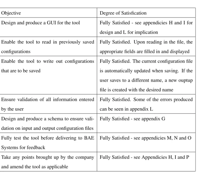
To enable the aim to be completely satisfied, the following objectives must be met: • Design and produce a GUI for the tool
• Enable the tool to read in previously saved configurations
• Enable the tool to write out configurations that are to be saved
• Ensure validation of all information entered by the user
• Fully test the tool before delivering to BAE Systems for feedback
• Take any points brought up by the company and amend the tool as applicable
1.6
Minimum Requirements
In order to achieve the aims of this project, the following minimum requirements must be met:
1. View and Edit configuration Files.
• The tool should be able to view the current configuration and allow the user to edit any details as they may wish. The user should be able to chose whether they want to save over the original configuration or save it to a new name.
2. Manage and Load previously saved conifurations.
• The tool should allow the user to open/load previously saved configuration files and then update the file that is used to produce the physical IP Addresses and Ports so that the current configuration is set up on reboot.
3. Enforce correct syntax of input and output configuration files
• The tool should automatically check that the files being read in and written out comply to a previously written schema. If the input file has incorrect syntax, the tool should alert the user of the error. If this error is produced on start up, default values should be used. If this error occurs on loading another configuration, the current configuration should remain..
4. Validate user input
• The tool should check every field that the user inputs and validate it against a previously agreed set of values for the specified field. If the user enters an invalid piece of information, the tool should alert the user and allow them to re enter the information. Invalid information will never be saved to a configuration file.
Any other features added to the software will be an aditional benefit to the tool, not specifically required by BAE Systems but of benefit to them.
1.7
Possible extension of minimum requirements
If any of the following are met, the overall system will be of greater use to the company:
1. Function to allow easy addition of new interfaces
• An additional function could be added to the tool to allow a SAINTT team user to add new interfaces to the tool. This function must only be allowed to be used by a SAINTT team member and so should be password protected. After adding new interfaces to the tool, the team member will have to deliver the new tool to those who may need it. The additonal feature would produce the required additional menu items and GUI screens and produce the code for the correct configuring of the interface. This feature would be very beneficial to the team but would also be quite complex. The main reason being that it would be very difficult to devise a generic form of interface specification that would be appropriate to any possible interface.
2. Manual
• If there is time, a manual should be provided to the team so that they can forward it to any member of the company who currently use the SAINTT system. It could also be beneficial to the SAINTT team members themselves in case they are ever called out to support a problem with the new tool
1.8
Deliverables
There will be one deliverable for this project, possibly two if extended requirements are carried out. The main deliverable will be the software tool itself which should be delivered on CD. The possible addi-tional deliverable would be a user manual, which should be in website format for use on the company’s intranet.
1.9
Relevance to degree
This project will require many skills learnt thoughout the past four years. The main skills required are programming (SE10, SE20, SE24 and experience from work placement), knowledge management
(DB32) and human computer interaction (GI11). It is clear that many other skills will also be required which will be learnt along the way.
1.10
Project Schedule
In project management, it is very important to have a schedule to follow to ensure the project is com-pleted correctly and on time. There are many ways of producing a schedule, Gantt Charts being a widely known and used way. This way of scheduling enables you to keep track of your plan as well as your actual work load, so that you can make any adaptations needed if it becomes clear you are widely be-hind schedule. An initial Gantt Chart was created for this project but along the way it became clear that some alterations were needed. Certain sections were no longer needed and additional sections had to be added. All versions of the Gantt Chart can be located in Appendix C.
Chapter 2
Background Research
2.1
Introduction
This chapter will look into the current ‘system’ used at BAE Systems. It will also explore many different aspects required to create the new system, looking at advantages and disadvantages where appropriate and explaining how each aspect can be used in the new system.
2.2
The Current System Used
Currently BAE Systems do not use a specific computerised system to set up their computers. Instead, they use a configuration file which is edited when new configurations are required. The file contains all the information required by the computer so that, on start up, the correct IP Addresses and Ports are set up. A sample configuration file currently in use can be seen in Appendix D.
It is quite clear that this approach is very inefficient and quite a ‘hacky’ way to set up the computers. The current system means that it is quite easy, and possible, to incorrectly set up the computer and it also means that setting up is very tedious. The new system will need to take into account the current values stored in the configuration files and use the same approach to set up the actual IP Addresses and Ports (ie on start up).
2.3
Primary Research
Since I carried out a years placement at BAE Systems on the SAINTT team, I have first hand experience of how the current system works and how the configuration files must be altered in order to set up different interfaces (systems). I will take my years experience into account when producing the solution and I will ensure constant feedback from the current team members throught the production of the solution.
2.4
Secondary Research
In order to produce an accurate solution, I first need to do some research
2.4.1 IP Addresses and Formats
The system produced to solve the problem will need to validate information entered by the user to set up configurations for the computers. One of the pieces of information needed from the user will be an IP Address. The following section explores the format of IP Addresses to gain the required knowledge to validate the user input.
2.4.1.1 Research
In researching IP Addresses and their formats, it was realised that there are more than one type of IP Address. In fact there are many different classes of address that can be used for different things. [1] explains the basics of the format of an IP Address, sumarised as follows:
• An IP Address must consist of four numbers
• Each of these numbers must be between 0 and 255
• No IP Address can consist totally of 0s or 255s
• Each number is seperated with a ‘.’
For example, 123.45.67.89
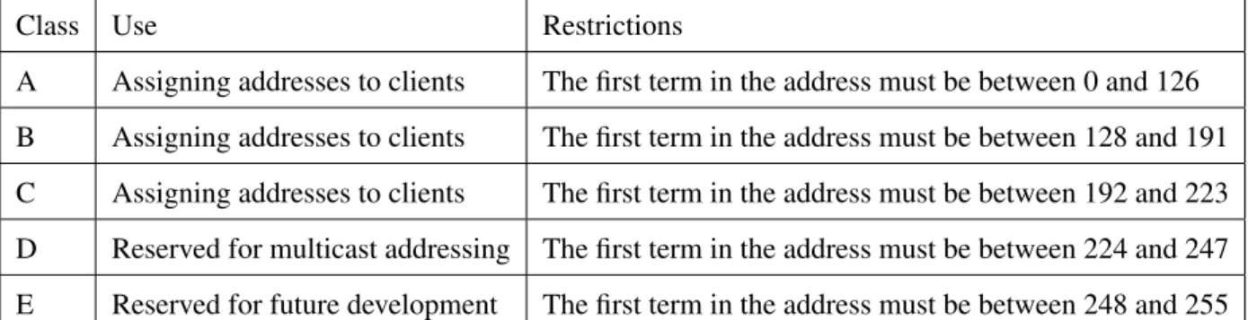
When it came to looking into the various classes of IP Address, it became apparent that there are five different classes in total; Class A, Class B, Class C, Class D and Class E. [2, 3] explain these classes in
Class Use Restrictions
A Assigning addresses to clients The first term in the address must be between 0 and 126 B Assigning addresses to clients The first term in the address must be between 128 and 191 C Assigning addresses to clients The first term in the address must be between 192 and 223 D Reserved for multicast addressing The first term in the address must be between 224 and 247 E Reserved for future development The first term in the address must be between 248 and 255
Table 2.1: Different IP Address Classes
more detail. Table 2.1 was constucted by combining summaries of both books. It was also noted that the networking number 127 is reserved for the ‘local loopback’ which is used for trouble shooting. Each class has a subnet mask assignment which follows the same format as an IP Address but is used to define which parts of the IP Address refer to the network address and which refer to the node address. There are default subnet masks associated to classes A–C which are 255.0.0, 255.255.0.0 and 255.255.255.0 respectively.
2.4.1.2 In relation to the Problem
With regards to the problem in hand and after speaking with the Product Manager, it was agreed that the IP Addresses in the system produced will simply comply to the basic rules stated above along with the rule that the third term of the address must be the node Id (this is a unique number that enables the identification of each node on each interface). Since the final system will be used by BAE Systems, the actual IP Addresses that will be used are secret and so that part of the system will need altering by the company themselves. Due to this, it was decided that no extra time should be put into validating the IP Addresses to comply with any of the four classes and a simple validation should be used.
2.4.2 Document Markup Languages
The input and output files used for the system to load and save configurations will be written in a document markup language. This next section explores the most common markup languages.
2.4.2.1 HTML Research
When looking into which markup language to use for the input and output files, [4] proved to be very useful. After reading over what [4] had to say about HTML, it became clear very quickly that there were more disadvantages to the markup language than advantages. For example, it was learnt that not all computer programming languages are able to read in and write out HTML, making it quite obvious that this markup isn’t best suited for the input and output of files in the system being produced. It was also learnt that HTML is hard to read for a human due to the tags being nested and overlapped and, for the same reason, HTML can be complex to write since the writer needs to know all the tags and what they all mean. The final point that helped in a decision being made was that HTML is hard to debug -the omission of a simple tag can takes ages to resolve.
2.4.2.2 XML Research
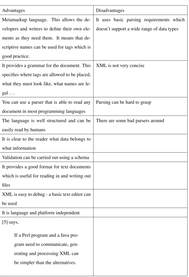
XML is another markup language that was based on HTML. [5] discusses the advantages and disad-vantages of using XML and goes into detail on what XML is. As a summary, we learn that XML is a metamarkuplanguage that is used for text documents. A metamarkup language is one that does not have fixed tags and elements that have to be used - the user can specify the names of both. The data entered is written as a string and is surrounded in tags, a bit like HTML.
Table 2.2 summarises the advantages and disadvantages of using XML, obtained from [5, 6]: As can be seen, there are a lot more advantages than disadvantages.
When it comes to parsing XML using most languages, there are two different API’s that can be used; SAX and DOM. There is also data binding which is used with regards to Java.
2.4.2.3 In relation to the problem
After taking into account the above findings, it is obvious that XML should be used in relation to the problem. Since the system is going to need to read in and write out files as well as validate information, XML seems to be the best option as it can do this all in one. Since it has not been decided what programming language is going to be used, it is probably best to look into using DOM or SAX APIs when parsing XML into the program.
Advantages Disadvantages Metamarkup language. This allows the
de-velopers and writers to define their own ele-ments as they need them. It means that de-scriptive names can be used for tags which is good practice.
It uses basic parsing requirements which doesn’t support a wide range of data types
It provides a grammar for the document. This specifies where tags are allowed to be placed, what they must look like, what names are le-gal . . .
XML is not very concise
You can use a parser that is able to read any document in most programming languages
Parsing can be hard to grasp
The language is well structured and can be easily read by humans
There are some bad parsers around
It is clear to the reader what data belongs to what information
Validation can be carried out using a schema It provides a good format for text documents which is useful for reading in and writing out files
XML is easy to debug - a basic text editor can be used
It is language and platform independent [5] says,
If a Perl program and a Java pro-gram need to communicate, gen-erating and processing XML can be simpler than the alternatives.
2.4.3 Computer Programming Languages
When deciding what programming language to use for the product that is to be created to solve the problem, it seemed a good idea to look into those languages that a basic knowledge of is already known. So, both Java and C++ were researched.
2.4.3.1 Java Research
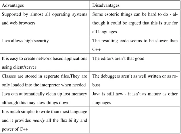
Table 2.3 shows the advantages and disadvantages of using Java which has been collated by summarising information obtained from [7, 8]
2.4.3.2 C++ Research
[8] was also used to look into the advantages and disadvantages of C++ as shown in Table 2.4 [8] also states:
C++ is an object-oriented language, and when you program well in C++, you are think-ing about objects and their responsibilities. Tiny programs in C++ look very much like programs in C, but larger C++ programs are completely different.
2.4.3.3 In relation to the Problem
Looking at the advantages and disadvantages of C++ and Java above, along with the fact that the most recent language I have used is C++, it has been concluded that C++ should be used to code the system to solve the problem. It appears C++ has more resources and help with regards to parsing XML and I have had previous experience parsing with this language. When discussing this conclusion with the Product Manager, it was agreed that this was a good choice, especially since the Software Engineers at BAE Systems only know C++ and not Java and they will be required to keep the system up to date in the future.
2.4.4 GUI Design and programming
Since one of the important factors of the solution is that the system is easy to use and must have a pleas-ant graphical interface, it is importpleas-ant to look into how to design such a system and, more importpleas-antly, how to program it.
Advantages Disadvantages Supported by almost all operating systems
and web browsers
Some esoteric things can be hard to do - al-though it could be argued that this is true for all languages.
Java allows high security The resulting code seems to be slower than C++
It is easy to create network based applications using client/server
The editors aren’t that good
Classes are stored in seperate files.They are only loaded into the interpreter when needed
The debuggers aren’t as well written or as ro-bust
Java can automatically clean up lost memory although this may slow things down
Java is still new - it isn’t as mature as other languages
It is much simpler to write than most language and it provides nearly all the flexibility and power of C++
Table 2.3: Advantages and Disadvantages of Java
Advantages Disadvantages
The resulting program can be run on all plat-forms (although the code must be recompiled on each platform)
A relatively complex language (I already know how to code in C+ + so this doesn’t re-ally relate to me)
It has advanced features - memory can be ex-amined and adjusted directly
Subtle bugs can be implemented very easily which can lead to memory ‘leaks’
Programs run quickly and take up little space in memory
It doesn’t support automatic clean up of lost memory
There are many ways to obtain the same result Memory can be overwritten Programs created are easier to obtain and are
more reliable
2.4.4.1 Design Research
When it comes to designing a GUI, there is a lot to take into consideration. A summary of things to remember and things to avoid can be seen in Appendix R. When creating the GUI for my program, I will ensure I adhere to as many of these rules as possible and try to maximise the usability of the GUI. Some key points I will remember are to ensure the layout of all windows is the same and, if not identical, then very similar, not to over complicate the program by trying to help the user, use icons where appropriate but don’t confuse the user by using icons relating to another function. When designing the GUI, it is important to think about the different types of people who are going to be using the program; their age, their ability, their competance etc. It is important to design a GUI that appeals to all the prospective users. In order to ensure the GUI is appropriate, designs will be discussed with the Technical Authority Manager of SAINTT and amendments will be made where necessary.
2.4.4.2 Programming Research
After researching programming a GUI, it appears that there are a few different ways that it can be done. Firstly, there is a program on linux that can be used to create the GUI. This program is called Glade and works by creating an XML file which contains all the details of the GUI. In this program, you can create every window and dialog needed and using the properties menu you are able to name every ‘widget’ for use in the code later. It is also possible to add all signal handlers to buttons, menu items etc using Glade and name them as required for later use. To use the GUI created with this program, the Glade library must be linked into the makefile when creating the program from the code. Within the code, a call must be made to open the XML file created by Glade followed by a call to automatically connect the signal handlers to the ‘widgets’. However, as far as can be seen, Glade is only compatible with C++, not Java. Since earlier on in my research I decided it would be best to use C++ over Java, Glade is an option I could use.
Another option is to use the GTK library and create the GUI within my code by hand. This could be quite time consuming but is another option. In this case, all signals would be connected to widgets when needed. If this option was to be used, it would be a good idea to have a seperate class that creates a basic window and one that creates a basic dialog. These classes could then be used everytime a new window/dialog was to be created and by providing certain methods, the required changes could be made when necessary.
Finally, there is a library called gtkmm that could be used. This library provides a basic generation of every widget provided by GTK and would be used in my code by inheritance. This option seems to be a better way of creating the GUI than the hard coding using GTK, since a lot of the code is already done for you within the library. It would be a lot quicker and simpler than coding from scratch.
2.4.4.3 With relation to the problem
Many of the design aspects mentioned above are for larger, more complex systems than the one being produced. Those that are relevant to this solution will be taken into account when producing an initial GUI design. More importantly, the design will be presented to the Technical Authority Manager of SAINTT and the feedback will be used to create the final design before any programming is carried out. It appears that Glade works well with C++ and provides a simple and easy way of producing the GUI. This will be the approach used for the solution. [11, 12] will be used to help with using Glade.
2.4.5 Schemas and Grammas
Since I am using XML for my configuration files, it would be a good idea to look into using a schema or grammar with the file to ensure correctness of the file. This would ensure that all files being read in are of the correct format and contain all the right tags in the correct order for the program.
2.4.5.1 Research
After reading a few books on XML Schemas, it appears that there is more than one type of schema to chose from. The following information was obtained by sumarising the content from [13] and [14]. DTD’s
Standing for ‘Document Type Definitions’, DTDs provide a source of tools for defining the element and attribute structures allowed in a document. It can also be used as a way to provide default values for attributes and for defining metadata information. They are widely supported and used although the capabilities provided have quickly been outgrown.
Some disadvantages of DTD’s are: • They don’t support namespaces • They have weak data typing
• You can’t define a root element
This last point means that it could be possible for a file to be ‘valid’ even if it is missing the first 4 elements, say, but has the rest of the elements correct.
On the other hand, DTD’s have the widest support in literature and software and have 10 data types available.
A DTD:
Declares a set of allowed elements - no other element name can be used other than those specified in this set.
Defines a ‘content model’ for each element - the content model is a pattern that specifies which elements or data can go inside an element. It also specifies the order the elements/data must be in, how many of each element/data can be entered and whether the element/data is required or optional.
Declares a set of allowed attributes for each element - the attribute declaration defines the name, datatype, any default values and the behaviour of the attribute. (The behaviour would be something like if the attribute is required or optional)
Provides a variety of mechanisms to make the model easier to manage. e.g, parameter entities and the ability to import pieces of the model from external files.
W3C
W3C Schemas define shared markup vocabularies and allow machines to carry out rules made by peo-ple. They provide a means for defining the structure, content and semantics of XML documents. It is a simpler schema to use since it is expressed in XML and is easy to read. The structures and datatypes are more similar to those of programming languages and a great benefit of this schema is that it has over 40 datatypes and the author can define their own custom types. Another benefit is that it offers object oriented features like polymorphism.
Relax NG
This is a relatively new type of schema and there’s not that much information available. From the little information obtained, it is clear that this schema is simple to use and provides schemas that are simple to read and write. It is possible to convert Relax NG schemas into other schema langages such as those mentioned above.
All schemas should begin with a text declaration. This looks like an XML declaration but it explic-itly excludes the standalone property. In this text declaration, you can specify character sets other than
the default and you can change the XML version number. Schemas must not contain a document type declaration.
It is possible to get software programs that create schemas for you, or at least aid you in the creation of them.
2.4.5.2 In relation to the problem
Having looked around for a program to aid the production of an XML schema, I have decided on using Altova XML Spy 2007 Enterprise. This program helps with the creation of W3C XML Schemas so this is the XML schema I have decided to use. The program provides an online tutorial which I will complete, making notes along the way. The notes created while performing the Altova tutorial can be seen in Appendix E
2.5
Previous Solutions
Although there are no computer systems available specific to this problem, there are other types of systems available that carry out some of the functions required by this solution. These will be looked at with the hope that they provide relevant help towards producing a solution.
2.5.1 PuTTy
PuTTy is a program used to connect to another computer. You can use it to connect to a Linux machine from a windows machine or simply between two machines. You need to know the IP Address of the computer you are connecting to as well as some other information. This program isn’t really very helpful to me since it doesn’t actually set up IP Addresses on the current machine which is what I am wanting to do. Also, to solve the problem in hand, there are many more constraints and certain sections of information that need to be obtained from the user depending on the ‘interface’ (system) being set up. The solution required is far too specific to the company for any pre existing software to be of use.
Other than PuTTy, there don’t appear to be any other programs that may be of any use. It appears that there is no software available to set up IP Addresses on a linux machine, there are only guides explaining how to do it manually.
Chapter 3
Methodology
3.1
Overview
In order to decide on a design methodology for my project, I decided to look up some existing method-ologies and use this information to create my own methodology, specific to my project. The existing methodologies I researched were the Waterfall model, Iterative model and Spiral model, gaining infor-mation from [15]. I decided it was best to split the methodology up into sections for the design, write up, evaluation and what I will do should any problems occur.
3.2
Design
When it comes to deciding on a methodology for the design of my software, it is important to decide on the various stages before deciding on how to apply each stage in a methodological fashion.
The different stages required to complete the software are; design the GUI, design a schema, code GUI, code input and output, code validation of data, code creating physical IP Addresses.
I think the best design methodology for the design is a combination of all three existing methodologies listed above. Through previous experience of coding, it is inevitable that problems/errors will occur where they are least expected and therefore the methodolody used needs to allow for this.
There are two stages in the design that will require feedback from BAE Systems, these are the design of the GUI and schema. Therefore, it is obvious that these two stages will follow a more sequential methodology where an initial design is created, it is passed to the company for feedback and then the design is updated in accordance to these views. This could cycle around many times until both the Technical Authority Manager and I are happy with the final outcome.
Coding the software will also follow quite a sequential approach but will have a lot more ’loops‘ within it to allow for amendments. It is not a reasonable design to say that the whole of the GUI coding will be done and then that section will be complete, it is obvious to me that this section will be reached again throughout the rest of the coding. For example, there may be a new window/dialog that is needed that I hadn’t initially thought of. If this is the case, wherever I am in the coding methodology, I will have to loop back to the GUI coding section before continuing where I was. The rest of the coding should follow the same kind of methodology as the coding of the GUI. Again, there will probably be times when I have to loop back to a previous section before I can continue, but this is what I expect.
To help keep myself on track, I feel it is important to create some milestones along the way. I think the most important ones with the coding are completing the GUI and completing the main coding (ie not the coding of creating the physical IP Addresses). These milestones can be seen in the Gantt Charts in Appendix C.
3.3
Write up
The design of the methodology for writing up my report won’t really follow any specific existing methodology. I think it is best to write up my report as I go along, so to speak. That is to say that I won’t simply complete the software and then begin with the write up. This would be a stupid design since there will be many aspects I will have forgotten about along the way. I feel it is much more effi-cient to keep the report going, a bit like an ongoing diary of events which is filled in as and when certain things happen. This ‘diary’ can then be touched up nearer the completion of the software to ensure it is correct and all the correct sections have been written about. I think this is a good idea as it will ensure I don’t miss any problems or thoughts during the coding while at the same time it won’t take all my time away from producing the software itself.
A milestone for the mid project report will be created as well as a milestone for completing the write up. These can both be seen in the Gantt charts in Appendix C.
3.4
Testing and Evaluating
Once the software is complete, it is necessary to test it. This will be done by following a ’test sheet‘ which I will create. This ensures that I remember to test everything and the results will be monitored. During this testing phase, I will also evaluate the software, commenting on the results of the test. This will be a very sequential process, taking one step of the test at a time and evaluating in the same way. Once I have completed the testing, it may (probably) be necesarry to make amendments to the software. Once this is complete, I will repeat the test sheet and record the results as before. This may be repeated many times before I am satisfied with the software. At this point, I will pass the program over to the Technical Authority Manager at BAE Systems, who will then test the software himself and provide me with some kind of an evaluation. If there are amendments needed here, they will be completed and again, this section will be repeated as many times as required.
Since the last part of the testing and evaluation is down to BAE Systems, I need to ensure there is enough time for them to get back to me before my report is due. Therefore, I will create a milestone to ensure I have enough time. This can be seen on the Gantt Charts in Appendix C.
It is also a good idea to constantly test my software while I am developing it, as it would be unrealistic to think I can code the whole software without making mistakes. After each section of coding is done, I will have to compile it and run it to check the correct events happen. This will all be taken into account when evaluating my project.
3.5
Problems
As stated before, it is inevitable that there will be problems along the way with my project. Therefore, I think it will be beneficial to make some kind of a plan as to what to do when/if the time arises.
3.5.1 Re Designing
It may occur that I need to re design my plan for the project if such a problem arises that can’t be fixed for some reason. In this case, I will take a step back and look at the Gantt Chart to date and re design the schedule for the future, taking the problem into account. When initially creating my schedule for the project, I allowed myself a lot of extra time just incase an unforeseen problem came up and I needed time to fix it.
If this is the case, I will have to discuss my new plan with the Technical Authority of SAINTT and agree on any changes to be made. This will severely delay my project so I am hoping it won’t be the case!
3.5.2 Enhancing
Assuming no problems are found and that the project runs smoothly, I am hoping to add in some en-hancements to the program. Since I don’t know if I am going to be able to include any enen-hancements, I don’t think it is wise to use up my time planning the methodology behind creating the enhancement until I know if I have time or not. This is because I think it is inefficient to use up my time creating the methodology just for it not to be used, minimising the time I have to complete the project anyway. It would depend on which enhancement I chose to include as to how I would create the methodology anyway and the enhancement included would depend on how much time I have. I think the User Guide will be a lot less time consuming so if it looks as though I have a small amount of extra time near the end of the project, I will aim to get this done. On the other hand, if it appears that I have a lot of spare time, I will endeavour to get the ‘new interface’ enhancement completed. In either case, I will decide on the methodology at the time, although I am sure it will closely follow one of those described above.
3.5.2.1 User Guide
In order to create the user guide, I will follow quite a sequential approach. The user guide needs to be in web format so that BAE Systems can put it on their website. I think the best way to produce the guide is to carry out the main actions while at the same time constructing each section of the guide. Once the main sections are completed, I will go back and carry out the smaller, more minor actions and document these as I go along. Once the guide is complete, I will present it to the Technical Authority of the SAINTT team for their comments.
Chapter 4
Design
4.1
Configuration Files
The first thing to design is the layout of the configuration files that are going to be read in and written out. To do this, it is a good idea to look at the existing format of the configuration file (can be seen in Appendix D) and design the new ones around that.
Since the new files are going to be written in XML, it would be a good idea to first think of the different tags that will be needed. The purpose of the file is to contain the information for various ‘interfaces’ (systems) as well as some information specific to the current setup but not specific to the interfaces. Therefore, it is an idea to have an ‘Interface’ tag and an ‘Other information’ tag.
The next stage in the design of the configuration files is to research what tags are needed within each different interface the software is intended to work for. It may be necessary to ask the Technical Au-thority Manager of SAINTT for some guidance here.
The final configuration file template can be seen in Appendix F. Of course, it will depend on the con-figuration that is currently set up as to which interfaces will be in the actual concon-figuration file read in or written out.
4.2
Schema
Now a template has been designed for the configuration files, it makes sense to design a schema to ensure the XML files are in the correct format and contain the correct tags in the correct order (where necessary). I think it is important to send the initial design of the schema to the Technical Authority at the SAINTT team to ensure that no mistakes have been made in my interpretation of the old configuration file. It may be necessary to make amendments to the schema as a result of this.
4.2.1 Initial Design
The initial design will be created using Altova XML Spy 2007. Looking at the configuration file created in Appendix F, it is easy to see the tags that are needed in the schema. What isn’t so clear is the rules that go with the tags. After discussing certain issues with the Technical Authority, it became clear that there were certain constraints on each interface the program should work for. The five interfaces that have been requested to be available in the program are called ‘DTS’, ‘Real Coupler’, ‘SimSaf’, ‘CSH’ and ‘LPD’. The reason these five have been requested is that they are all different and most other interfaces the company will need the program to work for are based on these five or are very similar.
One constraint on these interfaces is that the LPD interface can only appear once per configuration. The other four interfaces can appear as many times as the user wishes in each configuration. This means that in the schema, it would be better to have two different tags for the interface, one which allows any number of occurances between 0 and infinity and one which only allows the number of occurances to be 0 or 1.
I think it would be a good idea to create a ‘complex type’ for each of the five interfaces, these would each specify the format for each interface individually. Each interface follows the same kind of format but there are differences within them:
DTS
The DTS interface needs to contain the following information: Interface Type which will be fixed to ‘DTS’, Node Id which is a single number ranging from 1-255 (this number is a unique identifier for each interface type in the configuration), socket and extra information. Each tag must exist and must be in the order specified
The socket tag needs to contain the following information: Name which again will be fixed to ’DTS‘, Local IP Address, Remote IP Address and Port. Again, each tag must exist and must be in the specified
order.
The Port tag needs to contain the following information: Local Heartbeat, Destination Heartbeat, Man-agement, Reliable, Local Unreliable and Destination Unreliable, all of which should contain integers and must exist in the order specified.
Finally, the extra information tag must contain the information for Card which will hold a single num-ber, either 0 or 1 which informs the program of which network card the interface should be configured on.
The DTS Interface can also have an extra option of a ‘Snoop’ being added to it. This basically means that an interface will be created on both network cards for the given node Id. The specification for this will be detailed in another tag later.
Real Coupler
The Real Coupler interface needs to contain the following information: Interface Type which will be fixed to ‘Real Coupler’, Node Id which is a single number ranging from 1-255 (this number is a unique identifier for each interface type in the configuration), socket and extra information. Each tag must exist and must be in the order specified.
The socket tag needs to contain the following information: Name which again will be fixed to ‘Real Coupler’, Local IP Address, Remote IP Address and Port. Again, each tag must exist and must be in the specified order.
The Port tag needs to contain the following information: Local Heartbeat, Destination Heartbeat, Man-agement, Reliable, Local Unreliable and Destination Unreliable, all of which should contain integers and must exist in the order specified.
Finally, the extra information tag must contain the following information: Card which will hold a single number, either 0 or 1 which informs the program of which network card the interface should be config-ured on, TSM Transmission Method which must hold either ‘DTS Mode’ or ‘VLAN Mode’ and ATE Enabled which is a boolean and is optional. Other than the ATE Enabled tag, the other two must be present and in the order specified.
CSH
The CSH interface needs to contain the following information: Interface Type which will be fixed to ‘CSH’, Node Id which is a single number ranging from 1-255 (this number is a unique identifier for each interface type in the configuration), socket and extra information. Each tag must exist and must be in the order specified.
The socket tag needs to contain the following information: Name which again will be fixed to ‘CSH’ and Local IP Address. Again, each tag must exist and must be in the specified order.
Finally, the extra information tag must contain the information for Card which will hold a single num-ber, either 0 or 1 which informs the program of which network card the interface should be configured on.
SimSAF
The SimSAF interface needs to contain the following information: Interface Type which will be fixed to ‘SimSAF’, Node Id which is a single number ranging from 1-255 (this number is a unique identifier for each interface type in the configuration), socket and extra information. Each tag must exist and must be in the order specified.
The socket tag needs to contain the following information: Name which again will be fixed to ‘Sim-SAF’, Local IP Address, Remote IP Address and Port. Again, each tag must exist and must be in the specified order.
The Port tag needs to contain the following information: Local and Remote, of which both should con-tain integers and must exist in the order specified. Finally, the extra information tag must concon-tain the information for Card which will hold a single number, either 0 or 1 which informs the program of which network card the interface should be configured on.
LPD
The LPD interface needs to contain the following information: Interface Type which will be fixed to ‘LPD’, Node Id which is a single number ranging from 1-255 (this number is a unique identifier for each interface type in the configuration), socket and extra information. Each tag must exist and must be in the order specified.
The socket tag needs to contain the following information: Name which again will be fixed to ‘LPD’, Local IP Address and Port. Again, each tag must exist and must be in the specified order.
The Port tag needs to contain the following information: Link Port, which must contain an integer and must exist.
Finally, the extra information tag must contain the information for Card which will hold a single num-ber, either 0 or 1 which informs the program of which network card the interface should be configured on.
Snoop
itself. This tag should contain the following information: Interface Type which will be fixed to ‘Snoop’, Node Id which is a single number ranging from 1-255 (this number is a unique identifier for each inter-face type in the configuration) and Local IP Address.
Throughout all of the interfaces, the Local IP Address and Remote IP Address tags are of type ‘IP Address Type’ which is another ‘complex type’ of the formaterm (which is a number between 0 and 255), seperator (which is fixed to be ‘.’), term, seperator, term, seperator and term. This will ensure the IP Address entered is valid. Validating that the third term is the node Id can’t be done in the XML schema so it must be validated within the code.
So the overall schema must contain an Interface1 tag which can contain as many of the DTS, Real Coupler, CSH, SimSAF and Snoop interfaces, followed by an optional Interface2 tag which can only contain one LPD interface, followed by the following tags which must appear in the specified order: MaxFileSize which is an unsigned short that must be between 100 and 1700, Network Type which is a string that is either ‘eth’ or ‘znb’, Default Template Directory which is a string, Override Template Directory which is a string and Current Setup Directory which is also a string. The Schema used can be seen in Appendix G.
4.3
GUI
The GUI is an important part of the solution, it is important that it is a simple and clear design that is consistent throughout the various windows. The two most important aspects of the GUI are the navigation and the graphics.
4.3.1 Navigation
The navigation between the various windows should be smooth and simple. It is important that the user knows which window or dialog they are on and they shouldn’t be able to access any previously opened windows or dialogs without first closing the current one.
It is a good idea to keep the exit or back menu items in the same place on each window so that the user doesn’t have to search for it. It should be obvious to the user which options involve producing a new window, and new windows should only be used when necessary.
whole GUI. It is obvious that the configuration of each interface should produce a new window since this is a seperate entity.
The current setup of the computer needs to be viewable. This will display the currently loaded config-uration, current setup files directory, current override templates directory, default templates directory, max file size and network card type. I think this should be displayed in a new window also.
The nodes currently set up should also be viewable in a new window. This would be best displayed in some kind of a table with those nodes configured on card 0 on the left and those configured on card 1 on the right.
If the user wishes to change any of the current setup information, a dialog should appear where the user should specify the new information. The user should be able to save the changes or cancel.
When the user wishes to load a previously saved configuration, the usual select file dialog should be produced. This is the same dialog that will be used when the user wishes to save a configuration. Within the configure interface windows, it should be possible to view the currently configured ports and also the nodes configured for that interface type. The view of these nodes should be the same as the view of all of the nodes from the main window so as not to confuse the user. The view of the ports should be the same kind of view as the current setup from the main menu.
When the user chooses to add a node to an interface, a popup window should be displayed, showing the various attributes required for the operation. If the user chooses to save the added node, a dialog should appear informing the user that the save was successful. When deleting a specific node, it is wise to produce a dialog where the user specifies the node id of the interface they wish to remove.
If the user wishes to change the IP Address, a new window should be displayed with the current in-formation for the node they are wishing to edit. The user should then be able to edit either of the IP Addresses for that node and then save the node details. Upon selecting ‘Save’, a dialog should appear informing the user that the save was successful.
If the user wishes to change the port numbers that are configured, a new window should be produced, allowing the user to make the changes they wish. It should then be possible to either reset the ports to what they were originally or to save the new port numbers.
4.3.2 Graphics
Although graphics shouldn’t be used too much, it is an idea to use some graphics where possible so that the user knows what the button does without having to read and take in the label. I think it would be a
good idea to use stocks on all buttons possible. Since stocks are used in many programs, they will aid the user remarkably and speed up any process they are carrying out.
4.3.3 Initial Design
The initial design of the GUI can be seen in Appendix H. It was then sent to the Technical Authority Manager of SAINTT and their comments were made.
4.3.4 Comments
The comments made by the SAINTT team can be seen in Appendix P
These comments will be taken into account and a new design will be drawn up and approved by the Technical Authority Manager.
4.3.5 Final Design
The comments made in Appendix P were taken into consideration and my own views used to create a final design. I thought it would be a good idea (if possible) to have a tool bar at the top of any windows, as well as menu bars, which display the most commonly used options as buttons. If available, these buttons will display a stock item for each option.
The final design can be seen in Appendix I. It was approved by the Technical Authority Manager of SAINTT.
Chapter 5
Implementation
This section details the implementation of the solution for my project. It outlines any problems occured and how each problem was fixed or overcome.
5.1
GUI
The first part of the implementation was the GUI. After carrying out background research (section 2.4.4.3), I decided it would be most efficient to use ‘glade’ to design the GUI. When doing this, I followed the design produced (Appendix I) as closely as possible and at all stages I named each widget and component with self explanatory names for later use within my code.
Creating the GUI within Glade proved to be simple and efficient and it enabled me to get the GUI to look exactly how I wanted it to look. A selection of the windows can be seen in Appendix J.
5.1.1 Problem I
After creating the GUI using Glade, it was time to begin coding and get my program to produce the GUI on startup. Again this seemed to be very simple and, after using Glade tutorials [11, 12] I had the GUI being produced as required.
when clicked/changed. In order to do this, when creating the GUI, I had to attatch signals to every widget this was needed for. In order to connect the signals, one simple method had to be called in my code. Following the tutorials, this method had to be called after loading in the Glade XML file. After compiling the code, I ran the program but many warnings were produced informing me that it could not find the signal handler for every signal I added to the GUI.
I checked my code thoroughly against the tutorial and used a debugging program called gdb on linux to check what line of code was producing the errors. Sure enough it was when calling the method to connect the signals that all the warnings were appearing. No matter how much I checked my code and looked at the tutorials, I could not see the problem.
I contacted two previous colleagues who worked with Glade while I was working on SAINTT, explain-ing my problem. They both suggested various thexplain-ings to try but to no avail. I contacted the Technical Authority at SAINTT, telling him of my problem, but no one was able to work out the problem. Getting desperate, I joined a forum that had a newsgroup for people having problems with Glade [16]. I posted my question but never got a response. I also replied to a thread on the Glade website asking someone who had previously had the same kind of problem if they found a solution and if so, what it was but again got no reply.
Finally, I joined the school of computing newsgroup for C++ but no one replied to my post. I then decided I was getting too far behind schedule to continue like this, it was time to make a decision. Ap-pendix K shows the code I was using and the warnings produced, along with some of the emails I sent and received along the way.
5.1.2 Solution I
I now had two choices. I could either manually connect every signal or I could create the whole GUI from scratch manually (by coding). I thought it would be a good idea to try to manually connect every signal since it would take less time that coding the whole GUI manually and it was possible to test the solution by first connecting just a few signals, minimising the amount of wasted time should this solution fail too.
[17] explained how to do this. So, following the book I began manually connecting some of the signals on the main window. The following method was added to one of my files and called as soon as the Glade XML file had been successfully loaded:
//method to connect signals to widgets
void Callbacks::connectSignals(GladeXML *xml) {
//obtain widget to connect signal to GtkWidget *currentConfigBrowse =
glade_xml_get_widget(xml,"currentConfigurationBrowseButton");
//connect signal to button
gtk_signal_connect(GTK_OBJECT(currentConfigBrowse),"clicked", GTK_SIGNAL_FUNC( on_currentConfigurationBrowseButton_clicked) ,NULL); } 5.1.3 Problem II
This solution didn’t get me very far. I had the same problem as before, the signal handlers couldn’t be found. This meant that I only had one solution left.
5.1.4 Solution II
I decided rather than coding the whole GUI from scratch, that I would use a library called gtkmm which provides basic code for all types of widgets and GUI components. All you have to do is compile your code with this library and then you can use inheritance to use the pre coded GUI components. This makes it a lot quicker and easier to create the GUI. For example, when producing a window, you inherit from the gtkmm window class and use simple methods to adapt the window to your preferences. For example, set title(‘title of window ’) allows you to set the title of the window to the title you want. I used many tutorials and API websites to help me produce my code ([18, 19, 20]). This was quite time consuming but once complete, the GUI worked fine, with no problems.
These problems made me quite behind schedule and it was due to this that I had to re do my Gantt chart to re schedule all the tasks I had left to do.
5.1.5 Final GUI
The initial creation of the GUI was acceptable but not perfect. On the main window and within each configuration window, there is a table that displays the nodes configured on each interface. The initial GUI displayed the correct information but there were spaces between nodes which didn’t look that good. I had a look at the gtkmm tutorial [18] and discovered a different widget that allowed you to specify which row and column text was entered to. I realised this would solve my problem but when I tried to use the new widget, I discovered that the version of the gtkmm library I was using was older than the one that had the new widget I wished to use. Therefore, I had to find the source code ([19]) and incorporate it within my code. This proved to be relatively simple since the new widget simply used widgets that I was already using but manipulated them to do other things. This meant that I could just replicate the code within my code and even meant I could personalise the code to be more suited to my program. Both versions of the GUI can be seen in Appendix L.
5.2
File I/O
After realising that trying to solve my GUI problem may take a while, I decided it would be beneficial to begin coding the file input and output since I didn’t really need the GUI to be able to do this. As decided in section 2.4.2.3 I am using XML for my configuration files. In order to read in and write out XML, a libray called xerces is needed. [21] contains an API which proved very useful in coding the file I/O.
In order to write the code to read in the XML file, I needed to closely follow the schema created (Appendix G) since reading in is done as a tree; reading in a node and then moving on to it’s child/sibling and reading in that node. It was a very sequential process to read in the XML file and apart from a few ‘blips’, it went very well.
The main problem I encountered was that there was an extra node after each tag but before the text within the tag. This meant that the first time I tried to read in an XML file, it crashed. This was because I was trying to access certain nodes in a way that wasn’t possible for their type. It took a little while to discover what the problem was but once discovered and the relevant alterations made, my program read in an XML file perfectly.
It was important that I remembered that the configuration file being read in could contain many sections detailing each ‘interface’, eg it is possible to have up to 50 DTS interfaces in one configuration. In order
to allow for this, many loops had to be coded in to ensure I allowed for many of each interface.
As the file was being read in, it was important to store the information required to be displayed since later on it would need to be passed to various other classes in order to display it in the correct places. In order to do this, a simple conversion needed to be made since by default the information obtained from the XML file is in a type specific to xerces. This conversion creates a C++ string which can then be used simply.
After reading in the file, various variables had to be deleted or shut down so as to prevent memory leaks. When thinking about how the program was going to be used, I decided it would be best to write out a temporary XML file everytime the user pressed the ‘save changes’ button in the configure interface windows. This is because it was easier to update the main window’s display of configured nodes by reading in an XML file.
So, when the user pressed the save changes button, a method would be called in the configure io file that wrote out the configured nodes to a temporary XML file. This file would then either be deleted or renamed depending on whether the user decided to save their configuration or just quit without saving. Writing out XML using xerces was also quite simple. Again a conversion was needed to convert the strings into the xerces form of a string and then the reverse method used to retrieve the information was used to write out the information. Before actually writing the information, each tag had to be created and inserted into the XML tree in the correct place. Again, loops were required where there were more than one of the same interface configured.
Once all the tags and information were written to the file, the file was closed and again, certain variables were deleted or correctly shut down to prevent memory leaks.
5.3
Validation
When the user enters information to the program, it is important that it is validated. This is to ensure that incorrect information is not written out to the XML files and that no problems occur later in the program. There are various different validations required.
5.3.1 Node Id
The node Id entered for each configured node must be a number in the range 1 → 255 inclusive. It must also be unique to the nodes configured on each seperate interface. (e.g a DTS node 3 and Coupler
node 3 are allowed but two DTS node 3s are not allowed). So, when the user enters the node Id being configured, it must be checked against all existing nodes on that interface. If it already exists, when the user presses the ‘OK’ button, they are informed that the node already exists and they are then displayed with the same dialog so that they are able to alter the node Id to something different.
5.3.2 IP Addresses
When the user configures a new node on any interface (node here is referring to the collection of IP Addresses and node Id on each interface), the IP Addresses must be unique. The way the GUI is set up, when adding a new node on a certain interface, the user is prompted to enter the node Id and IP Address(es). When the node Id is entered, if the user presses the return button, the default local IP Address (and Remote IP Address if applicable) is automatically filled in. The user is then able to change this if they wish. When pressing the ‘OK’ button, the information in the IP Address entry box(es) is obtained and run through a series of checks. First of all I check if it is the default IP Address, since if it is, no further checks are required. If it isn’t, I then check that there are 4 terms (4 numbers) and 3 sperators (.’s). If this test is passed, I then check that the four terms are all numbers in the range 1→255 inclusive. No matter what address the user enters, the third term of the address must be the same as the node Id being configured. Therefore, if all other tests are passed, the next test is that the third term is the same as the node Id entered. Finally, a test is carried out to ensure that no other configured node has the same IP address. If at any point in the validation the test fails, a string is set to hold information of the error that has occured. At the end of the validation, this string is passed back and if there is text stored in it, an error message is brought up explaining the error and the user is shown the ‘Add node’ GUI they were previously at so that they can fix the problem.
5.3.3 Network Card
The user selects the network card they wish the node to be configured on by using a combo box which contains the options 0 or 1. If when pressing the ‘OK’ button, one of these numbers hasn’t been selected, an error message will be produced informing the user. They will then be displayed the same ‘Add Node’ dialog so that they can rectify the problem.