guidelines for designers /
builders
Bord Gáis Networks Requirements and Technical Recommendations for
Connecting Industrial and Commercial (Non–Domestic) Gas Loads.
Definition
In the context of this guidance document, an industrial / commercial connection constitutes the addition of any non-domestic gas load to the natural gas distribution network.
Table of Contents
section 1:
introduction n Table of Contents 2 n Introduction 4n Scope / Irish Standards 5
section 2:
The benefits of natural gas
n Why Natural Gas? 6
n Electricity Generation CHP 7 n Space Heating 8 n Water Heating 9 n Catering 9 n Cooling 9
Section 3:
Organising a natural gas connection 10
Section 4:
Site work guidelines 12
n Gas Main Guidelines 13
n Site Ground-Work Guidelines 13
n Gas Services Requirements 14
Section 5:
Meter types & specifications
n Gas Load Categories 15
n Specifications of Commercial and Industrial
n Meter Types 16
n On-Site Fabricated Meter Assemblies 17
n Meter Modules 18
n Skid Units 19
n Base Requirements for Skid Units 21
n Guidelines for Positioning Pressure
n Reduction and Meter Installations 22
n Steel Cage Protection 24
n Purpose Built Meter Compartments 25
n Locating Meters inside the Building 27
Section 6:
Installation pipework downstream of the meter
n Gas Supply Pipework 29
n Service Shafts 34 n Installation Pipework 36 n Appliance Connections 37 n Means of Isolation 37 n Material Selection 38 n Corrosion Protection 38 n Jointing 39 n Pipework Support 40 n Pipes in Voids 40 n Sleeving 41 n Pipe Sizing 42 n Conversion Tables 44 n Safety Devices 45
n Design for Protection in Case of Fire 45
n Identification of Pipework 46
n Equipotential Bonding 46
n Marking of Meters & Supply Pipework 46
Section 7:
Non-domestic premise certification
n The Non-Domestic Certificate 47
n Steps to Getting Meter Fitted 48
n Completing the Declaration of Conformance 48
n Testing of Pipework 50
n Strength and Soundness Testing 51
n Flue Testing 52
n Ventilation 52
n Project Manager/Gas Installer Responsibility 53
n Operator Responsibility 53
Section 8:
Appendix:n Gas Market Deregulation Terminology 54
n Gas Load Terminology 55
n Technical Terminology 56
n Connections Form (Sheet 1 & 2) 61
n Applicable Standards for Industrial/Commercial
Natural gas is found in large basins underneath the earth’s surface. Once brought from underground, the natural gas is treated to remove impurities like water, sand, and other compounds. After this cleaning process, a trace of a proprietary chemical is added to give the natural gas its identifiable odour before it is transmitted through a network of pipelines to its point of use.
Introduction: from shore to door
Section 1: Introduction
Businesses in Ireland have increasingly adopted natural gas as the preferred fuel for:
Steam Generation typical applications include
industrial processes and electricity generation.
Combined Heat and Power (CHP) typical applications include hospitals, large hotels and leisure centres.
Heating, Hot Water and Cooking typical applications include hospitals, shopping centres, factory workshops, offices, restaurants and public houses.
If you OWN or MANAGE a business and you are considering a connection to the natural gas network, then this booklet will be of assistance to you.
Since its establishment, Bord Gáis has developed a combined Transmission and Distribution pipeline network of 11,318km (year end 2005). The system is linked to UK and Continental gas markets through two subsea interconnector pipelines. Natural gas is now available in over 100 population centres within 19 counties throughout the country with over 540,000 gas users in Ireland.
This document has been prepared for the prospective gas customer, the construction industry professional and the mechanical contractor who wish to connect to the natural gas network.
This booklet is a guidance document for natural gas distribution systems at pressures less than 5bar. Gas mains, services and meters transporting gas at pressures greater that 100mbar are not permitted inside the building line1 of occupied properties. Consult Bord Gáis Networks for site specific clarification.
Information contained within this document includes gas mains and service requirements, technical guidance relating to gas meters for a range of gas loads and installation requirements downstream of the meter. This document contains practical guidance and should not be a substitute for the current Irish Gas Standards, the Technical Guidance Documents (Building
Regulations) or the Local Government (Multi-Storey Buildings) Act 1988.
The requirement for the safe and efficient supply of piped natural gas to industrial/commercial premises (at meter outlet pressures less than 5bar) are contained in the current edition of I.S.820, “Non-Domestic Gas Installations”.
As stated in Irish Standard I.S.820, only competent persons2 are permitted to design, construct and commission gas installation pipework. The standard also states that competent personnel should only commission gas consuming equipment and appliances. Competent persons engaged in the design of gas installations and in gas installation work should comply with the current Building Regulations and the Local Government (Multi-Storey Buildings) Act 1988.
The work and responsibility of the installation designer and mechanical contractor begins at the point
of delivery3 and continues up to and including all installation pipework and gas consuming equipment.
The requirements for the installation of domestic type appliances in non-domestic buildings are set out in I.S. 813, “Domestic Gas Installations”. The requirements for the pipework supplying these appliances is included in I.S. 820 “Non-Domestic Gas Installations”.
The requirements relating to the installation or maintenance of industrial process equipment, be it either an appliance or a piping system, is not included in this booklet.
For guidance on industrial installations with a
maximum operating pressure greater 0.5bar (500mbar) or installation requiring a supply pressure exceeding 5 bar consult I.S./EN 15001-2.
In the event of any conflict between this document and the relevant Irish Standards, the current edition of the Irish Standard should prevail.
All values for length are in millimetres unless otherwise stated.
1, 2, 3 Refer to Section 8: Appendix – Terminology.
Scope / Irish Standards:
Why natural gas?
Since the 1980’s more and more energy users have adopted natural gas as their primary source of fuel for heating, cooking and processing. Currently there are in excess of 540,000 customers connected to the natural gas network in Ireland.
There are several reasons why the change to natural gas has taken place:
n Optimising use of valuable space – with natural gas there is no need for an on site tank, external boiler house or excessively large installations consuming premium landscape, commercial or parking space.
n Compact reliable appliances – due to the clean combustion of gas, often the appliances and equipment are smaller than for alternative fuels. This cleaner combustion process also means natural gas appliances and equipment are more reliable and often easier to maintain. Space usage within the building is thus optimised and costs reduced with high fuel efficient equipment. n Natural gas is very versatile and has many uses
– from cooking to heating to generating a site’s electrical requirements through Combined Heat and Power (CHP), see page 7 for further details. n There are fewer carbon emissions with natural
gas than with other fuels. Gas is cleaner
than alternative fossil fuels as it
produces less harmful pollutants during combustion, hence making it a more
environmentally friendly fuel and suited to direct firing applications.
n Natural gas is piped directly from a national and European network and is always ‘on-tap’. You only pay for natural gas when you use it, not in advance. There is no need to worry about on site storage, circulatory or conditioning systems. n Gas remains the most cost effective fuel on the
market. See the Sustainable Energy Ireland’s website at www.sei.ie for the most up-to-date fuel price comparisons. The price of natural gas is regulated by the Commission for Energy Regulation (CER).
With all of the benefits above there is no doubt that when combined with modern equipment a natural gas connection can reduce the running costs of your property.
There are many applications of natural gas and a range of appliances available to complement each application. The following pages provide examples of natural gas in use. For more information and details on particular appliances please contact a natural gas appliance and equipment supplier.
Large Processing Loads and Large Electricity
Generation Facilities:
Very large natural gas consuming processing plants require a connection directly from high pressure transmission pipelines. Bord Gáis Networks transmission pipelines provide natural gas to numerous facilities in the Republic of Ireland, as well as an electricity generating station in Northern Ireland and on the Isle of Man.
The Bord Gáis Network transmission and distribution network can be viewed on the internet at www. bordgais.ie.
Combined heat and power (CHP):
The requirements relating to the installation or maintenance of industrial process equipment, be it either an appliance or a piping system, are not included in this booklet. For guidance on industrial installations with maximum operating pressure greater than 0.5bar (500mbar) or any installation requiring a supply pressure exceeding 5bar. Reference can be made to I.S./EN 15001-2.
10% to 20% Waste
Electricity, Heat and Hot Water 80% to 90% efficiency Factory, Hospital, Hotel or Leisure Centre Natural Gas Meter C.H.P. 100% Energy Input Figure 1:
The operating principles of CHP installation
Figure 2: CHP unit
CHP uses gas to provide both heat and electrical power. The CHP unit burns gas to power a generator which in turn creates electricity. This electricity is then fed into the main fuse board for the site, reducing the electricity demand from the national grid. The result is lower electricity costs for the end user. The heat from gas combustion is used to heat water in the usual way for the heating system. This process results in very high efficiencies and an overall fuel cost reduction for the property.
An added advantage is that as a site is generating part or all of its power, if there is a failure on the electricity
grid, power will still be available to maintain essential operations. Larger CHP users can sell excess electricity back to their electricity supplier and so reduce their electricity bills even further.
CHP has become an innovative solution for hotels in Ireland, in particular large hotels that have leisure facilities and swimming pools. As more towns in Ireland are connected to the natural gas network and technology has become more advanced, it is now possible for small CHP units to become a more viable option for a greater range of applications.
Space heating:
There are several ways natural gas can be adopted to provide the heating of premises. Below are just some of the options available.
Warm Air Heaters
Warm air heaters are available in multiple formats such as free-standing, wall or ceiling mounted, all of which have different heat output ranges. The heaters are a tried and tested method of cost effective heating. They can form part of warm air curtains above doors and loading bays.
Radiant Heaters
Gas fired radiant heaters have particular useful applications within large open areas. These units only direct heat to a desired area. There are two types of gas fired radiant heaters, radiant plaques or radiant tubes. Both utilise a radiant surface which directs heat to the desired area.
Central Heating Boilers
Central heating boilers are available in a wide array of sizes and heat outputs, meeting the needs of domestic and commercial customers. Condensing warm air heaters are also available which function in a similar fashion and can operate at efficiencies in excess of 95%.
Balanced-Flue Convector Heaters These units are small convenient heaters for smaller buildings and premises requiring intermittent heating, such as offices and small shops. These are local heaters which combust gas, releasing heat to the desired area and release products of combustion to atmosphere via their own flue.
Figure 3:
Small Commercial (Domestic Type) Central Heating Boiler
Figure 5: Warm Air Heater Figure 4:
Water heating:
Central Heating BoilersThe standard domestic central heating boiler or multiples interlinked provide both the heating and hot water requirement. In certain instances, a separate smaller boiler with a calorifier can be more efficient, while gas fired appliances which heat the water directly are even more efficient.
Instantaneous Water Heaters
Instantaneous water heaters are ideal for local small quantities of hot water. There are a range of appliances available which can heat several litres of water per minute.
Storage Water Heaters
These gas heaters have a high recovery rate which can reduce the need for large on site storage. There is a broad range of models available and these are particularly suited to large quantities of hot water, stored either centrally or local to usage.
Catering:
Natural gas is the fuel of choice for professional caterers; its flexibility and instant response make it the fuel that is in greatest demand for chefs today. There are a wide range of gas cooking appliances available, from small restaurants to large hotel kitchens. Equipment such as convection ovens, deep fat fryers, griddles, combination ovens and gas ring hobs give the full range of applications. Gas heated dishwashing machines are available for cleaning of cutlery,
glassware and crockery. Appliances specifically for the fast food industry, such as gas heated conveyor boilers and fryers are also available.
Cooling:
Gas fired absorption chillers have a very low level of noise and vibration. The majority of units are available as chillers/heaters which provide cooling and heating operations from the one unit. This dual functionality provides efficient and therefore economic operation.
Figure 6:
Storage Water Heater
Figure 7: Central Boiler Figure 8:
Section 3: ORGANISING A NATURAL GAS CONNECTION
Information required for a gas connection:To process your application for a gas connection it is essential that the following information is provided to Bord Gáis Networks. The listing below highlights the
minimum required to design the connection and accurately evaluate the capital
contribution required.
Natural gas is delivered through a pipework distribution system and supply pressures vary in accordance with the design and operation of the system local to the premise being connected. To confirm availability of necessary gas volume and pressure contact Network Connections at 1850 427 747.
The route for supplying natural gas to a building and final location of the point of delivery8 (normally the meter) is decided by Bord Gáis Networks following consultation with the customer or the customer’s nominated representative.
The gas main, service, pressure reduction and primary meter(s) remain the property of Bord Gáis Networks.
Installations are designed to deliver 21mbar, unless otherwise requested. Bord Gáis Networks do not supply gas at pressures greater than those available from the local network9.
In accordance with the current CER
Connections Policy, a design fee is applicable for large connection applications with an Estimated Annual Consumption (EAC) above a published value. Consult the Bord Gáis Networks website for further details, www.bordgais.ie.
Refer to Appendix for Connections Form and Page 11 for the schedule to Coordinate a Natural Gas Connection.
4
A Connections Form should be
completed for all connection requests. A sample form is provided in Section 8 of this booklet. An electronic version is
available on request from connect@
bge.ie and on the internet at www. bordgais.ie
5, 6, 7, 8, 9 Refer to Section 8: Appendix –
Terminology.
Table 1:
The information required to organise gas connection. a. Connections Form 4
b. Site Location Drawing (to be sent to [email protected])
c. Proposed Meter Locations shown on Drawing (to be sent to [email protected]) d. Estimated Annual Consumption (EAC) 5 (or, note point y below)
e. Maximum Hourly Quantity (MHQ) of Gas Required 6
f. Pressure Required (Meter outlet pressure normally provided at 21mbar) g. Details of Possible Future Loads
x. Minimum Hourly Quantity (average)
(Only required if Category 3 Connection, see table on page 15) y. Historic Fuel Bills
(Only required when premise is changing over from an alternate fuel) z. Gas Point Registration Number, GPRN 7
Individual GPRN Number(s) Assigned to each Gas Meter to be Fitted:
Schedule for Co-ordinating Business Connections 1.
Customer/Customer’s Representative contacts Bord Gáis Networks on 1850 427 747 to acquire details of existing gas network in area. 3. Bord Gáis Networks will arrange a meeting to agree the network route and positioning of gas meters and ancillary equipment prior to proceeding with project design and estimation. Private way leave agreements to be sought by Customer where applicable. 4. When the above details are finalise d, Bord Gáis Networks design the gas connection and provide written quotation, proposed gas network drawings and contract documents to the Customer. 5. Customer returns signed contract with connection fee. 6. Bord Gáis Networks seek way-leave permissions from local authorities. CONSTRUCTION PHASE - Bord Gáis Networks 1. Customer’s project manager contacts Bord Gáis Networks on 1850 427 747 to acquire details of existing gas network within scope of site and safety labels for site. 2. Customer’s project manager liaises with Bord Gáis Networks pipe laying contractor to co-ordinate site works. FINAL METER CONNECTION - Natural Gas Supplier 1. Consumer contacts a natural gas supplier and agrees terms of supply (Referencing their GPRN). 2. Mechanical Contractor / Heating Installer prepares installation for meter fit, completes the “BGN Office Copy” of the Non-Domestic Certificate of Conformance and faxes it to 1850 211 447. 3. Consumer requests fitting of meter through their gas supplier (Not Bord Gáis Networks). 4. Bord Gáis Networks fit the meter after request from the consumers’ nominated natural gas supplier (if the Certificate of Conformance is completed and available on site). 2. Customer/Customer’s Representative contacts Bord Gáis Network Connections on 1850 427 737 requesting a Connections Form. This should be completed and returned with a site location map and site layout drawings to [email protected] . DESIGN PHASE - Bord Gáis Networks DATE: . . . / . . . / . . . . . . / . . . / . . . . . . / . . . / . . . . . . / . . . / . . . . . . / . . . / . . . . . . / . . . / . . . . . . / . . . / . . . . . . / . . . / . . . . . . / . . . / . . . . . . / . . . / . . . . . . / . . . / . . . . . . / . . . / . . . Project Number Assigned:
GAS
Section 4: site work requirements
Site work guidelines
Cabinet containing gas meter and pressure regulator Pavement Carriageway Supply Pipework External Isolation Valve Gas Service I.S 265 I.S 329 Service Top Tee Gas Distribution Mains I.S 820 Note:
n Gas mains, services and meters transporting gas at pressures greater than 100mbar are not permitted inside the building line of occupied buildings
n PE piping is not permitted inside the building
n The service should travel as near perpendicular to the gas main as possible
190mm 200mm
The external isolation valve and access cover should remain accessible at all times.
Figure 9:
Gas
Main Water Main
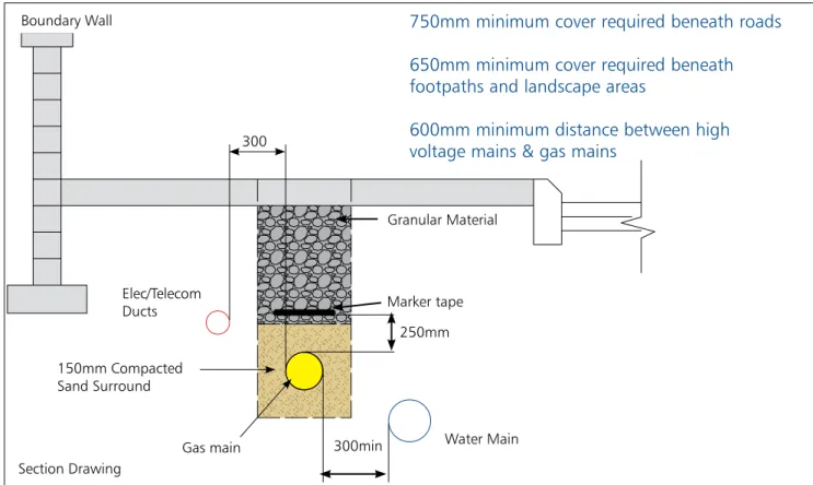
300mm min Inspection Chamber (Manhole) Boundary Wall Section Drawing Granular Material Marker tape Water Main
Gas main 300min
300
Elec/Telecom Ducts 150mm Compacted Sand Surround
750mm minimum cover required beneath roads 650mm minimum cover required beneath footpaths and landscape areas
600mm minimum distance between high voltage mains & gas mains
250mm
3
Note:Other utilities/ducts should not be laid on top of gas main/service
Gas mains (i.S. 329)
All gas mains should be installed by Bord Gáis Networks or a Bord Gáis Networks appointed contractor. On new–build projects, the builder normally provides a pre-excavated trench. All trenches constructed for the purpose of accommodating gas main should allow for a minimum cover of 750mm. Gas mains should not be laid with cover greater than 1200mm, unless specified by Bord Gáis Networks.
The total trench width should amount to outside diameter of gas pipe, plus 300mm.
Sand or pea gravel, 150mm minimum should surround the gas main. The trench should be reinstated as soon as practicable after the main is laid so to reduce the possibility of damage on site. The typical layout of a gas main in a footpath is shown in Figure 11 below.
Site ground-work
Guidelines
Under no circumstances may the
gas main be included in an inspection chamber
with other utilities / services or drainage / sewage systems. A distance of 300mm should be provided when a gas main is placed adjacent to an
inspection chamber (note Figure 10 below).
Figure 10:
Permissible proximity of gas mains to inspection chambers
GAS SERVICES (I.S. 265)
All gas services should be installed by Bord Gáis Networks or a Bord Gáis Networks appointed contractor in a pre-excavated trench, normally provided by the builder. Any extra site works required by Bord Gáis Networks will incur additional charges. The gas service should be laid in a straight line to the meter location, as near perpendicular to the gas main as practicable.
n Mains, services and meters transporting gas at pressures greater than 100mbar may not be positioned within the building line of occupied premises (as defined by I.S.329 / I.S.265). n For more detailed information, always refer to
the Bord Gáis Networks drawings specific to the project.
Service Requirements:
1. The trench for the gas service to each meter location should be excavated to a sufficient depth to allow a minimum cover of 600mm. In the case where the service supplies a single G4 meter box (per page 17) with a single meter contained within, 600mm minimum cover is required up to 1.5 metres from the meter box. Within the remaining 1.5 metre distance, cover may reduce to a minimum of 375mm to the base of the GRP sleeve (note Figure 9 on page 12). 2. All gas trenches should be excavated to the width
of the outside diameter of pipe, plus 300mm. 3. Sand or pea gravel, 150mm minimum should
surround the gas service.
4. Where the necessity to cross or run in close proximity to any other utility occurs, a minimum clearance of 300mm is required.
n All new industrial and commercial services should incorporate an underground service isolation valve which should remain accessible to
Bord Gáis Networks and the Emergency Services.
5. Marker tape (provided by the Bord Gáis Networks contractor) should be placed over all gas mains, services and ducting intended for gas distribution pipe insertion at a later date.
6. Bord Gáis Networks should be consulted if it is proposed to place the service in a sleeve or duct.
Meter types & specifications
Industrial and Commercial customer gas meters can be classified into the following three categories:
The meter will not be fitted unless any required meter protection has been installed.
Table 3: The Range of Gas Meters available
CATEGORY 3: Generally Skid Units
Peak gas load greater than 1,035 kWh (GL > 3,531,566 BTU’s)
G100, G160, G250, G400, G650, SP1, SP2 - SKID UNITS:
Step 1: Pressure Reduction Skid manufactured off-site (refer to pages 19 & 20)
Step 2: Concrete Base placed in Bord Gáis Networks agreed position by client or builder (refer to page 21)
Step 3: Pressure Reduction Skid placed on concrete base
Step 4: Protection is placed around the skid installation
Step 5: Meter fitted and commissioned on-site after receipt of Declaration of Conformance, refer to Section 7.
CATEGORY 2: Generally Meter Modules
Peak gas load greater than 165 kWh and less than 1,035 kWh (563,003 BTU’s < GL < 3,531,566 BTU’s)
G16, G25, G40, G65 - METER MODULES:
(Refer to page 18 for further details)
Step 1: Meter modules manufactured off-site
Step 2: Module fitted and meter commissioned on site after receipt of Declaration of Conformance, refer to Section 7.
CATEGORY 1: Generally On-Site Fabrications
Peak gas load less than 165 kWh (GL < 563,003 BTU’s)
G4, G10 – METERS:
(Refer to page 17 for further details)
Step 1: Meters fitted on-site by Bord Gáis Networks meter fitter, after receipt of Declaration of Conformance, refer to Section 7.
Peak gas load (gl) categories
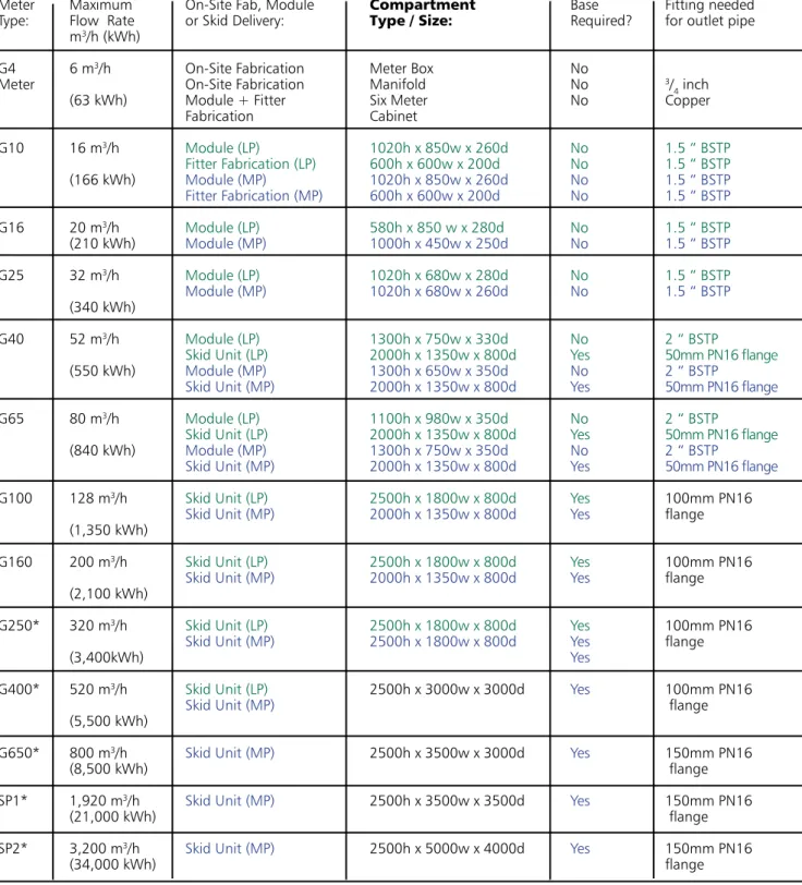
Meter Maximum On-Site Fab, Module Compartment Base Fitting needed
Type: Flow Rate or Skid Delivery: Type / Size: Required? for outlet pipe
m3/h (kWh)
G4 6 m3/h On-Site Fabrication Meter Box No
Meter On-Site Fabrication Manifold No 3/
4 inch
(63 kWh) Module + Fitter Six Meter No Copper
Fabrication Cabinet G10 16 m3/h Module (LP) 1020h x 850w x 260d No 1.5 “ BSTP Fitter Fabrication (LP) 600h x 600w x 200d No 1.5 “ BSTP (166 kWh) Module (MP) 1020h x 850w x 260d No 1.5 “ BSTP Fitter Fabrication (MP) 600h x 600w x 200d No 1.5 “ BSTP G16 20 m3/h Module (LP) 580h x 850 w x 280d No 1.5 “ BSTP (210 kWh) Module (MP) 1000h x 450w x 250d No 1.5 “ BSTP G25 32 m3/h Module (LP) 1020h x 680w x 280d No 1.5 “ BSTP Module (MP) 1020h x 680w x 260d No 1.5 “ BSTP (340 kWh) G40 52 m3/h Module (LP) 1300h x 750w x 330d No 2 “ BSTP
Skid Unit (LP) 2000h x 1350w x 800d Yes 50mm PN16 flange
(550 kWh) Module (MP) 1300h x 650w x 350d No 2 “ BSTP
Skid Unit (MP) 2000h x 1350w x 800d Yes 50mm PN16 flange
G65 80 m3/h Module (LP) 1100h x 980w x 350d No 2 “ BSTP
Skid Unit (LP) 2000h x 1350w x 800d Yes 50mm PN16 flange
(840 kWh) Module (MP) 1300h x 750w x 350d No 2 “ BSTP
Skid Unit (MP) 2000h x 1350w x 800d Yes 50mm PN16 flange
G100 128 m3/h Skid Unit (LP) 2500h x 1800w x 800d Yes 100mm PN16
Skid Unit (MP) 2000h x 1350w x 800d Yes flange
(1,350 kWh)
G160 200 m3/h Skid Unit (LP) 2500h x 1800w x 800d Yes 100mm PN16
Skid Unit (MP) 2000h x 1350w x 800d Yes flange
(2,100 kWh)
G250* 320 m3/h Skid Unit (LP) 2500h x 1800w x 800d Yes 100mm PN16
Skid Unit (MP) 2500h x 1800w x 800d Yes flange
(3,400kWh) Yes
G400* 520 m3/h Skid Unit (LP) 2500h x 3000w x 3000d Yes 100mm PN16
Skid Unit (MP) flange
(5,500 kWh)
G650* 800 m3/h Skid Unit (MP) 2500h x 3500w x 3000d Yes 150mm PN16
(8,500 kWh) flange
SP1* 1,920 m3/h Skid Unit (MP) 2500h x 3500w x 3500d Yes 150mm PN16
(21,000 kWh) flange
SP2* 3,200 m3/h Skid Unit (MP) 2500h x 5000w x 4000d Yes 150mm PN16
(34,000 kWh) flange
All flange pipe connections should include a gasket * Meter Bypass Available, subject to evaluation. Refer to terminology for further details.
Refer to pages 17 to 20 for further details. Green text indicates low pressure and blue text indicates medium pressure.
Notes:
Final specification of meters by Bord Gáis Networks Gas Main, services and meters transporting gas at pressures greater than 100 mbar are not permitted within the building line of occupied premises
Under no circumstances is PE piping permitted inside the building
Table 4: Full range of meters indicating Type, Maximum Flow Rate, Minimum Compartment Sizes and Outlet Supply fitting required.
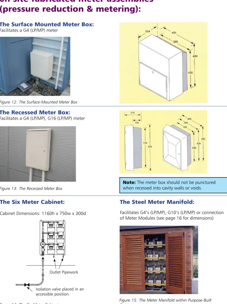
Note: The meter box should not be punctured when recessed into cavity walls or voids.
0n-site fabricated meter assemblies
(pressure reduction & metering):
The Surface Mounted Meter Box:
Facilitates a G4 (LP/MP) meterThe Recessed Meter Box:
Facilitates a G4 (LP/MP), G16 (LP/MP) meterThe Six Meter Cabinet:
Cabinet Dimensions: 1160h x 750w x 300d
Isolation valve placed in an accessible position.
Outlet Pipework
The Steel Meter Manifold:
Facilitates G4’s (LP/MP), G10’s (LP/MP) or connection of Meter Modules (see page 16 for dimensions)
Further information on the G4 meter, meter cabinet and manifold options refer to in Booklet 1, pages 5 – 12 and Booklet 3, pages 3 – 8.
Both the Steel Meter Manifold and Six Meter Cabinet are manufactured off-site to facilitate multiple meter connections.
Each of the above installation options should be placed a minimum of 300 mm above finished ground level.
Figure 12: The Surface-Mounted Meter Box
Figure 13: The Recessed Meter Box
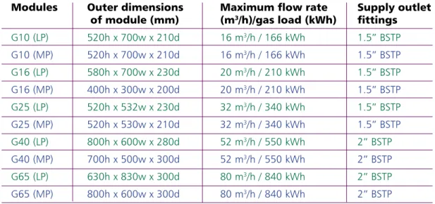
Pre-fabricated meter modules (pressure
reduction & metering):
Meter modules are surface mounted and arrive on site assembled and pre-locked.
When delivered they require a gas service connection carried out by Bord Gáis Networks or a Bord Gáis Networks nominated contractor. The supply pipework connection is carried out by the client’s nominated gas installer.
Only after these connections are complete can the module be unlocked and the meter commissioned. The clients nominated gas installer should be on-site for co-ordination of commissioning and verification of the Declaration of Conformance10.
Typical Applications:
Small to medium sized commercial customers (note maximum kWh and maximum flow rates below).
Low Pressure (LP) meter modules are connected to a gas distribution network of less than 100mbar. The standard module outlet pressure is set at 20mbar.
Meter Module Positions
Medium pressure (MP) meter modules are connected to the gas distribution network of pressure greater than 100mbar. Under no circumstances may the medium pressure steel or polyethylene service, including meter module, be positioned within the building line12 of occupied premises. Each meter
module should be placed a minimum of 500mm above finished ground level.
Meter Module Specifications
Table 5: Technical details for Meter Modules.
Modules Outer dimensions Maximum flow rate Supply outlet
of module (mm) (m3/h)/gas load (kWh) fittings
G10 (LP) 520h x 700w x 210d 16 m3/h / 166 kWh 1.5” BSTP G10 (MP) 520h x 700w x 210d 16 m3/h / 166 kWh 1.5” BSTP G16 (LP) 580h x 700w x 230d 20 m3/h / 210 kWh 1.5” BSTP G16 (MP) 400h x 300w x 200d 20 m3/h / 210 kWh 1.5” BSTP G25 (LP) 520h x 532w x 230d 32 m3/h / 340 kWh 1.5” BSTP G25 (MP) 520h x 530w x 210d 32 m3/h / 340 kWh 1.5” BSTP G40 (LP) 800h x 600w x 280d 52 m3/h / 550 kWh 2” BSTP G40 (MP) 700h x 500w x 300d 52 m3/h / 550 kWh 2” BSTP G65 (LP) 630h x 830w x 300d 80 m3/h / 840 kWh 2” BSTP G65 (MP) 800h x 600w x 300d 80 m3/h / 840 kWh 2” BSTP
Figure 16: A G25 Meter Module connecting a complex of offices in Naas, Co. Kildare
10 Refer to Section 7: Certification of
Non-Domestic Gas Installations.
Skid Unit Specifications:
* Meter Bypass Available15, subject to Bord Gáis Networks evaluation.
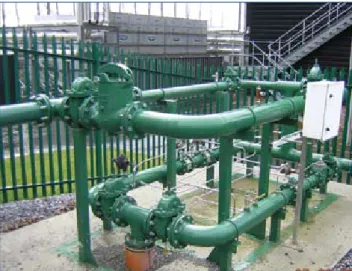
Skid units (pressure reduction & metering):
Skid units are delivered to site assembled and pre-locked. They are positioned and supported on a concrete base provided by the client / builder (refer to page 21 for further details). When delivered they require a gas service connection organised by Bord Gáis Networks or a Bord Gáis Networks nominated contractor, and a supply pipework connection carried out by the client’s nominated gas installer.
Only after these connections are complete and appropriate protection provided can the skid unit be unlocked, the meter fitted and the completed installation commissioned. The clients nominated gas installer should be on-site for coordination of commissioning and verification of the Declaration of Conformance13.
Typical Applications:
Large commercial premises and industrial processing loads (note maximum kWh and maximum flow rates below).
Meter Space Maximum flow rate Supply outlet
Required (m3/h) / maximum fittings
Gas load (kWh) G40 (LP) 2000h x 1350w x 800d 52 m3/h / 550 kWh 2” BSTP G40 (MP) 2000h x 1350w x 800d 52 m3/h / 550 kWh 2” BSTP G65 (LP) 2000h x 1350w x 800d 80 m3/h / 840 kWh 2” BSTP G65 (MP) 2000h x 1350w x 800d 80 m3/h / 840 kWh 2” BSTP G100 (LP) 2500h x 1800w x 800d 128 m3/h / 1,350 kWh 100mm PN 16 flange G100 (MP) 2000h x 1350w x 800d 128 m3/h / 1,350 kWh 100mm PN 16 flange G160 (LP) 2500h x 1800w x 800d 200 m3/h / 2,100 kWh 100mm PN 16 flange G160 (MP) 2000h x 1350w x 800d 200 m3/h / 2,100 kWh 100mm PN 16 flange G250 (LP)* 2500h x 1800w x 800d 320 m3/h / 3,400 kWh 100mm PN 16 flange G250 (MP)* 2500h x 1800w x 800d 320 m3/h / 3,400 kWh 100mm PN 16 flange G400 (MP)* 2500h x 3260w x 2240d 520 m3/h / 5,500 kWh 100mm PN 16 flange G650 (MP)* 2500h x 4400w x 2500d 800 m3/h / 8,500 kWh 150mm PN 16 flange SP 1 (MP)* 2500h x 4000w x 3050d 1,920 m3/h / 21,000 kWh 150mm PN 16 flange SP 2 (MP)* 2500h x 4800w x 3150d 3,200 m3/h / 34,000 kWh 150mm PN 16 flange
Figure 17 & Figure 18: A SP1 meter connecting a
pharmaceutical plant in Athlone, Co Westmeath and a G65
unit placed in a naturally ventilated basement14 connecting a
hotel in Sandyford, Co. Dublin.
Table 6: Technical details for Skid Units 10 Refer to Section 7: Certification of
Non-Domestic Gas Installations.
Low Pressure (LP) skid units are connected to the gas distribution network of pressure less than 100mbar. The standard outlet pressure is set at 20mbar. Medium pressure (MP) skid units are connected to the gas distribution network of pressure greater than 100mbar. Under no circumstances may a medium pressure steel or polyethylene service, with meter, be positioned within the building line of occupied premises.
Protection in the form of a palisade fence or cage is included into the connection cost by Bord Gáis Networks (Refer to page 24 for further details). The customer may provide the required protection only if the design has been pre-agreed with Bord Gáis Networks. Note: The Meter will remain locked until protection has been installed.
Building Energy Management Systems (BEMS) are computer systems which enable the system operator to monitor and control building services including heating, air conditioning and lighting. BEMS are also capable of automatically recording gas and electricity consumption via the relevant meters and the data obtained can be used, for example, to analyse energy usage trends and to record and forecast annual energy consumptions.
Through on-line monitoring of energy usage, customers can identify and report on energy consumption data which will help to identify cost-saving opportunities and promote energy conservation between occupants and building managers.
Bord Gáis Networks is committed to promoting energy efficiency and if requested we can provide a Low Frequency (LF) Pulse Output from a Bord Gáis Networks meter. This device enables the BEMS to record the throughput of gas through the gas meter.
Electronic Daily Metering is necessary on all
connections with an estimated annual consumption (EAC)16 greater that 5.55GWh (5,550,000 kWh).
Electronic Daily Metering may be provided on skid units of lesser EAC’s after request from the client and evaluation by Bord Gáis Networks.
If a twin stream skid is specified, the customer / builder is recommended to request specific compartment and concrete base details from Bord Gáis Networks.
13 Refer to Section 7: Certification of
Non-Domestic Gas Installations.
14 Refer to Section 5, page 28:
Meters located in Open Basement Areas.
Base requirements for skid units:
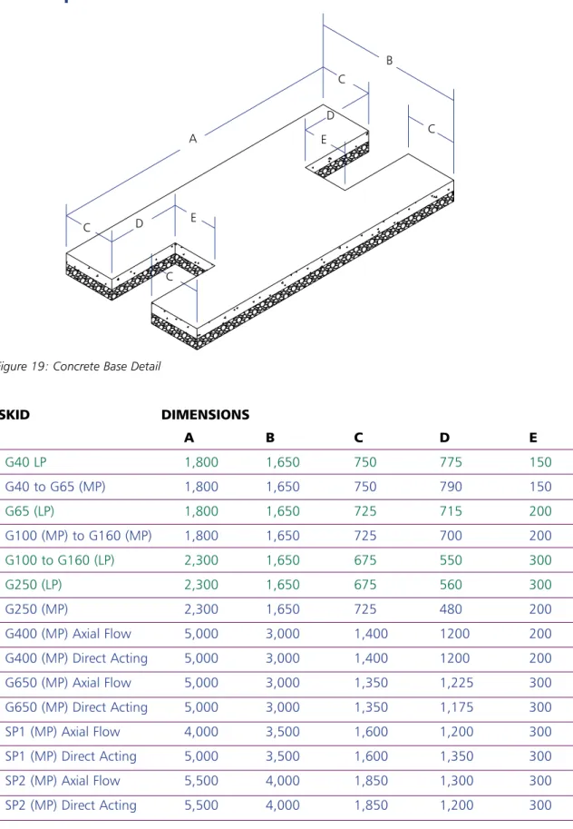
A B C D E G40 LP 1,800 1,650 750 775 150 G40 to G65 (MP) 1,800 1,650 750 790 150 G65 (LP) 1,800 1,650 725 715 200 G100 (MP) to G160 (MP) 1,800 1,650 725 700 200 G100 to G160 (LP) 2,300 1,650 675 550 300 G250 (LP) 2,300 1,650 675 560 300 G250 (MP) 2,300 1,650 725 480 200 G400 (MP) Axial Flow 5,000 3,000 1,400 1200 200 G400 (MP) Direct Acting 5,000 3,000 1,400 1200 200 G650 (MP) Axial Flow 5,000 3,000 1,350 1,225 300 G650 (MP) Direct Acting 5,000 3,000 1,350 1,175 300 SP1 (MP) Axial Flow 4,000 3,500 1,600 1,200 300 SP1 (MP) Direct Acting 5,000 3,500 1,600 1,350 300 SP2 (MP) Axial Flow 5,500 4,000 1,850 1,300 300 SP2 (MP) Direct Acting 5,500 4,000 1,850 1,200 300All skid units require a base consisting of concrete (150mm thick) placed on a consolidated hardcore (150mm thick). The builder/customer is responsible for placing the base in the position as agreed with Bord Gáis Networks.
If a twin stream skid is specified, request specific compartment and concrete base details from Bord Gáis Networks.
Dimensions may change subject to site specific requirements and should be confirmed with Bord Gais Networks at time of construction.
SKID DIMENSIONS
Figure 19: Concrete Base Detail
Table 7: Dimensions for sizing the concrete Base
B A C C D E E D C C
Guidelines for positioning pressure reduction
and metering installations:
n Bord Gáis Networks provide and lay all gas mains and service pipework up to and including the point of delivery (normally including the meter).
n Full access should be provided to the installation for Bord Gáis Networks authorised personnel at all times to facilitate construction of the meter installation and subsequent maintenance.
n Service pipework provided by Bord Gáis Networks for meters or pressure reduction equipment should be positioned prior to pouring of floor slab.
n The meter and/or pressure reduction equipment should be within the confines of the customer’s/ developer’s property and as close as practicable to the premise being supplied.
n Care should be taken when locating the external isolation valve so it is freely accessible at all times, e.g. not in a parking area where vehicles may restrict access (Note page 12).
n Planning permission should be obtained by the customer where necessary, i.e. for external structures designed to conceal or protect district regulator installations (DRI’s)17 and gas meters.
n Above ground gas services should only pass through naturally ventilated areas that are publicly accessible (i.e. providing access for Bord Gáis Networks maintenance at all times).
n Gas meter and ancillaries may not be placed in a space which may hinder escape in the event of an emergency.
n Meters should not be located where they may be exposed to accidental damage. Adequate protection should be provided by the customer/ builder against possible equipment damage or tamper. Installations in close proximity to a traffic area should be fitted with a suitable crash barrier.
n Underground natural gas pipework should be a minimum of 300mm from electrical mains. Gas equipment should not be positioned beneath overhead electrical cables or trees (applicable to skid units only, note pages 19 and 20).
n All meter installations should be located in a well-drained area that is not liable to flooding. Design and/or location should protect the meter and its connections against the possibility of corrosion. The meter installation should not be located directly beneath a ventilation grill or in a position liable to allow ingress of water unless weather protected.
n All meters and associated supply pipework should be earth bonded by the customer’s nominated electrical contractor in accordance with the current edition of the ETCI Regulations.
n Meters should always be positioned in an area of natural ventilation.
Protection of meter and pressure regulator installations:
Meters should not be located:
n adjacent to medium voltage (MV) electricity substations (minimum direct communicating distance of 10 metres required)
n in an area adjacent to L.P.G., or a flammable material storage area where paper, timber or chemicals are stored
n in an area adjacent to ventilation ducting or an air conditioning intake system
n where they may be exposed to extreme temperatures or ignition sources (e.g. switch gear, operating plant or where any spark
producing equipment are within close proximity). Electrical current carrying equipment or cables should not be in contact with or suspended from gas services, plant or meters
n in a position open to a stairway or protected shafts, lobbies or corridors, unless contained within a suitable compartment (per page 27)
n beneath a stairs, unless placed within a minimum two hour fire resistant and sealed compartment ventilated directly to atmosphere (refer to information regarding compartments on pages 25, 26 & 27).
Requirements:
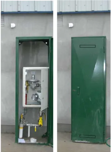
The structural containment for externally located meters may be either in the form of a pre-fabricated factory made compartment or module provided by Bord Gáis Networks (note pages 17 and 18), or purpose-built compartments
constructed by the builder / customer (refer to page 16 for minimum dimensions).
In the case of a steel manifold or skid unit,
protection from tamper and possible impact should be provided with palisade fencing caging, or equivalent (note pages 24 to 27). The emergency underground isolation valve, on the gas service, should remain accessible at all times (Note page 12).
The enclosure should provide adequate protection against weather and the possibility of tamper. Materials selected for construction of the enclosure should be weather resistant and durable.
Other utilities, materials or refuse, may not be placed within the same enclosure or be located within proximity to pose a safety risk.
If meters are to be positioned nearby passing traffic, a protective barrier should be placed around the installation. A suitably robust crash barrier should be constructed by the builder/customer and positioned so as to prevent any accidental damage to the gas installation.
C F E D B U T S S A
Steel cage protection (generally provided by bord gáis networks):
Figure 20: G160 MP skid unit with protection connecting a hotel in Bettystown, Co. Meath.
Figure 21: Diagram of Caged Protection
Table 8: Dimensions of caged protection for each meter arrangement.
Meters Types and A B C D E F S T U Pressure G40 (LP) G40 (MP) G65 (LP) 2000 1350 1500 1900 1000 750 450 1800 700 G65 (MP) G100 (MP) G160 (MP) G100 (LP) G160 (LP) 2000 1350 2000 1900 1000 750 450 1800 850 G250 (LP) G250 (MP)
Purpose-built meter compartments (constructed
by customer / builder):
To conceal gas meter and pressure regulator
equipment, the client, builder or architect may opt to build a purposely constructed compartment.
Bord Gáis Networks’ requirements for this compartment are as follows:
n Ventilation to atmosphere should be provided through a full height louvered door or suitably sized and constructed vents / ventilation ducts. High and low ventilation to the compartment should provide 5,000mm2 minimum free area each
or 1% of compartment floor area each, which ever is greater.
n Ventilation ducts should be protected and constructed to resist potential fire damage.
n Separation between the exits of each ventilating duct to atmosphere should be a minimum of 450mm. The high level duct should provide air, direct from atmosphere, to the extreme top of the compartment and the low level duct should be positioned a maximum of 150mm from the floor of the compartment.
n All voids within and around the compartment should be fully sealed and fire proofed to prevent the ingress of air or gas to a cavity or void in a building.
n Any walls should be of cavity free construction and the compartment should not include windows.
n All pipe exits from the compartment should be sealed with an approved fire sealing material per I.S. 820, I.S. 813 and building regulations (TGD’s), refer to page 41 for sleeving detail and requirements.
n If the compartment should contain electrical light fittings, they should be of approved sealed and spark proof specification. Standard electrical switch fittings and spark producing equipment are not permitted inside the compartment or within a proximity that may pose a safety risk. If it is proposed that meters be located in a compartment within a basement area, Bord Gáis Networks should be consulted for ventilation requirements and construction details on 1850 427 737.
Figure 22: G65 MP module with protection (provided by builder) for a warehouse facility in Arklow, Co Wicklow.
Pipes should have supporting brackets
400mm min.
Bord Gáis Networks supply and fit locks on the doors of compartments for district regulator installations DRI’s (Phone Network Maintenance at 1850 200 694). For access to meter compounds, the customer builder install locks that require an 8mm triangular key to lock and unlock. In doing so, both Bord Gáis Networks and the customer will have access to the meter.
Where locks are used to secure meter compartments, Bord Gáis Networks should be provided with keys and access to effectively respond to customer requests and possible emergency call-outs.
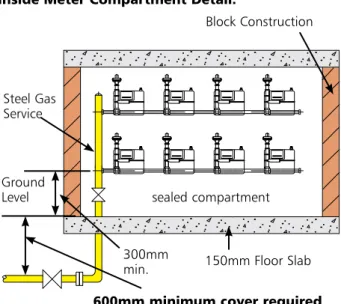
Block Construction Steel Gas Service Ground Level 150mm Floor Slab 600mm minimum cover required
300mm min.
sealed compartment
Figure 23: Plan view of gas meter compartment
Figure 24: Elevation view of gas meter compartment
Figure 25: Locked caged protection.
Figure 26: Lock provided by Bord Gáis Networks for DRI’s and customer sourced 8mm triangular key locks for meter compounds.
Locking devices and access
The dimensions of the compartment for available meter arrangements are available on page 12 of booklet 1 (for multiple G4 meters providing maximum flow rate up to 6m3/h each) and page 16
of this booklet, for each meter type. For Outlet Pipe Requirements see “Sleeving’
on page 41.
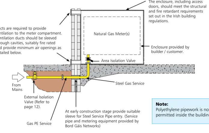
Inside Meter Compartment Detail: Plan Detail:
Figure 27: Compartment details for meters placed inside the building.
Ducts are required to provide
ventilation to the meter compartment. Ventilation ducts should be sleeved through cavities, suitably fire rated and provide minimum air openings as detailed below.
Gas PE Service
Steel Gas Service
At early construction stage provide suitable sleeve for Steel Service Pipe entry. (Service pipe and metering equipment provided by Bord Gáis Networks)
The enclosure, including access doors, should meet the structural and fire retardant requirements set out in the Irish building regulations.
External Isolation Valve (Refer to
page 12). Note:
Polyethylene pipework is not permitted inside the building. Area Isolation Valve
Natural Gas Meter(s)
Enclosure provided by builder / customer.
From Mains
Locating meters inside the building:
Only in situations where delivered natural gas mains pressure is less than 100mbar and it is not possible to locate meters externally, may meters be placed within the building line.
In addition to the minimum requirements set out in the previous pages, the following Bord Gáis
Networks specifications should be adhered to when placing meters inside the building.
n If recessed into the structure of the building or placed within the building, meters should be placed in a completely sealed compartment with the exception of access and ventilation provided by louvered doors or ventilation ducts provided direct to atmosphere.
n Meters should be positioned as near as practicable to the external wall where the gas service enters.
n Provision should be made for a steel service to enter into the building through a suitably robust and air-tight sleeve where traversing a cavity or void.
n On entry into the building, the gas service should only pass through a ventilated area that is publicly accessible (i.e. providing access for Bord Gáis maintenance at all times). The gas service may not pass through a protected corridor, stairway, shaft, refuse area or private premise (i.e. dwelling or commercial unit).
n The enclosure, including access doors, should meet the structural and fire resistant requirements applicable to that part of the building. Solid access doors to the compartment should be self-closing and non-lockable.
28
300mm min.
Natural Gas Meter(s).
Basement Ceiling External Isolation Valve (refer to page 12) P.E. Service
At early construction stage, provide suitable sleeve for Steel Service Pipe (service pipe and metering provided by Bord Gáis Networks)
NATURALLY VENTILATED AREA
Area Isolation Valve 300mm
min 1800mm min Natural Gas Meter(s) 600mm minimum cover required
Meters located in the open basement areas:
Meters located in an underground car park or openbasement area should only be positioned within a naturally ventilated space. Mechanical ventilation is never deemed acceptable if it serves the same basement or space as the gas service or meters. The meter installation should not be located directly beneath a ventilation grill or in a position liable to allow ingress of water, unless weather protected. If it is required that the meters or gas service be located in a dedicated room within the basement or in a basement lacking natural ventilation, Bord Gáis Networks should be consulted for specifications and ventilation requirements.
Figure 28: G4 metres serving retail units in Sandyford, Co. Dublin.
Figure 29: Illustration highlighting requirements when placing meters in a naturally ventilated basement
Section 6:
Customer pipework after the meter
Any person responsible for the design of gas pipework, construction of gas pipework, installation of gas consuming equipment and/or commissioning of installation should be a competent person.
Their responsibility commences from the Bord Gáis Networks point of delivery (normally the meter) up to and including all installation supply pipework and gas consuming equipment. Guidance contained within Section 6 of this document should only be referenced for installations at maximum operating pressures less than or equal to 100mbar. For guidance on supply pipework operating at maximum pressures greater than 100mbar refer to I.S.820. For industrial installations or installations requiring a supply pressure exceeding 5 bar consult I.S./EN 15001-2.
When designing and constructing natural gas installations, the key considerations are: A. Gas Supply Pipework:
Route of Pipework, Material Selection, Jointing, Isolation Points and Pipework Protection. (Current edition of I.S.820 and Section 6 of this Guidance Document)
B. Gas Consuming Equipment: B.1 Location (Permitted Locations)
-(The current edition of I.S.820, Manufacturer’s Instructions; I.S.813 - if domestic type appliance)
B.2 Flue (Disposal of Products of Combustion) -Route of Flue and Location of Flue Terminations,
(Current edition of I.S.820, Manufacturer’s Instructions; I.S.813 - if domestic type appliance)
B.3 Provision of Air (Permanent Air Supply for Gas Equipment) - Combustion Processes, Cooling of Equipment and Air Provision for Occupants,
(Current edition of I.S.820, Manufacturer’s Instructions; I.S.813 - if domestic type appliance) C. Commissioning of Gas Installation and Certification:
(Current edition of I.S.820 and Section 7 of this Guidance Document)
NOTE:
Pipework should be designed and
constructed to enable testing and purging to be carried out.
Pipework should be installed so that it does not impose excessive stress on devices or components incorporated into the pipework e.g. meters regulators, etc. A single premise may be supplied with natural gas with two or more meter points. Installation pipework may only be supplied from a single meter.
For commercial applications, pipework downstream of the point of delivery
(normally after the Bord Gáis Networks meter) should be designed to I.S.820 “Non-Domestic Gas Installations”. The requirements for the installation of domestic type appliances in non-domestic buildings are set out in I.S. 813, “Domestic Gas Installations”. The requirements for pipework supplying these appliances is set out in I.S. 820.
Both I.S.813 and I.S.820 contain section J, which highlight gas installation requirements for educational premises.
Gas Supply Pipework
External Pipework
Buried pipework
n All buried pipework should be protected against corrosion (per page 38). Protective sheathing should be checked for continuity before installation.
n Mechanical joints may not be used on buried metallic pipework.
Mechanical joints in accordance with I.S. EN 1555 may be used on buried PE pipework;
Pipework should be bedded in sand or fine filling to a depth of 150mm above and
below the pipe. The minimum depth of cover for the pipe is 375mm.
Pipework, which may be subject to vehicular loading, should be protected in a robust sleeve in addition to the minimum depth of cover of 375mm.
B - Boiler W - Water Heater AHU - Air Handling Unit
Local Gas Isolation. Refer to page 37.
Figure 30 shows a typical installation where a gas network connection is reduced in pressure and metered close to the site boundary. Natural gas is normally supplied to the customer at an operating pressure of 20 mbar, unless otherwise requested. Requests for pressure greater than 20mbar should be made at connection design stage.
External Pipework (General)
n Pipework should be resistant to corrosionand be electrically continuous (i.e. suitably earthed).
n Pipework should not be located near high voltage conductors, hot or chilled water systems or subject to vibrations unless appropriate measures are taken. n Ferrous pipe should not be connected
directly to copper piping.
The position of pipework in relation to other services should be such that it can function properly and be used with safety.
Gas Service Pressure Reduction and Metering Premise Plant Room Kitchen AHU AHU AHU AHU B B W Figure 30:
When laying external pipework by using a mole or by directional drilling, only polyethylene piping should be used. This operation should be carried out in accordance with I.S. 265.
External Pipework
Above-ground pipeworkExternal above-ground pipework should be: n adequately supported (refer to page 40); n protected against mechanical shock; n minimum communicating distance of 10
metres from medium voltage electrical substations
n positioned so to avoid spaces containing garbage chutes, transformers, sewage pipes and other sources of possible corrosion unless
Outer Wall DPC Steel sleeve to terminate 25mm from FFL. Mastic sealant to be injected between sleeve and service pipe
Grout between sleeve and concrete F.F.L. Metallic Pipe Sealant Grout Figure 31:
Below ground entry into building.
specific measures are taken (refer to
page 38).
n polyethylene pipework may not be used above ground unless protected against impact and protect against the ultraviolet rays from the sun. PE pipework should not be positioned where it may be subjected to excessive temperatures
n should be protected against the possibility of lightning strikes where appropriate
For more information on the protection of buried pipework, refer to page 38 of this booklet and I.S. 820.
Particular attention needs to be given to the design of pipework in areas known to be susceptible to ground movement.
External riser
Individual premises can be supplied with installation pipework constructed as external “risers” placed on an outside wall. For aesthetic reasons such ‘risers’ can be hidden within a false rainwater down-pipe or behind pre-fabricated expanded metal cladding (See Fig. 33 below).
If placing installation pipework behind a false PVC rainwater downpipe (backing removed), the downpipe should be left open top and bottom and secured to the wall.
The pipework within should be adequately supported as per page 40.
GRP cover fixed to wall Capillary soldered elbow Compression Fittings GRP sleeve bend 375mm min 32mm PE installation pipe PE transition coupling c/w wall
bracket
Local Isolation Valve
Figure 32:
Above ground entry into the building.
Figure 33:
External gas riser behind cladding
Internal Pipework (General):
n Pipework should pass through walls or
floors by the shortest possible route (refer to
sleeving on page 41)
n The installation of gas pipework should not impair characteristics of the building such
as fire resistance, mechanical stability, heat
retention and sound transmission.
n Pipework should be electrically continuous and suitably earthed (refer to equipotential bonding page 46).
n Gas pipework should not be routed in lift shafts, stairways forming a protected shaft or in protected escape routes / corridors (refer to pages 33 and 34).
n Pipework should not be located near high voltage conductors, hot or chilled water systems or subject to vibrations unless appropriate measures are taken.
n Gas pipework/equipment may not share the same room, duct space or void as air handling equipment or ducting.
n Polyethylene pipe should not be used within the building
n Pipework should be supported as per page 40.
The position of pipework in relation to other services should be such that it can function properly and be operated upon safely.
Note:
Gas Pipework in Protected Shafts: A protected shaft, corridor or lobby may not contain a pipe intended to carry gaseous or liquid fuels. The protected shaft should not contain a ventilating duct (other than a duct provided for the purposes of pressurising the stairway to keep it smoke free).
Definition of a Protected Shaft:
A protected shaft is defined as a shaft
which enables persons, air or objects to pass from one compartment to another
and is enclosed with fire resisting
construction.
For further clarification, consult The
Building Regulations, Section B.
Internal Pipework:
BuriedAll buried pipework should be protected against corrosion and should not compromise radon protection.
The minimum concrete cover for pipework in areas not subject to vehicular loading is 25mm. Pipework, which may be subject to vehicular loading, should adhere to the same depth of cover, sand surround and protective sleeve requirements as external buried pipework. Mechanical joints may not be used on internal buried pipework.
Any protective sheathing or coating should be checked over its entire length for continuity before covering takes place.
Provision should be made, to allow adequate
expansion and contraction of buried gas pipes where they are laid close to heating system pipework. Joints may be made by welding, brazing or soldering
with capillary fittings (see Jointing page 39). Joints are
not permitted if in close proximity to heating system pipework.
Internal Pipework:
Concealed pipeworkMechanical joints are not permitted on pipework if not readily accessible for maintenance.
Pipes passing through external walls, cavity walls, solid
floors or solid ceilings should pass through a sleeve
(Refer to page 41 for further details).
Rising copper pipework behind plasterboard should be suitably protected against the possibility of accidental impact or puncture.
Pipework in stairways
n Pipework should not be located in protected stairways or in protected corridors/lobbies. n Pipes located in other internal stairways
of a building are subject to the following requirements:
n the stairway should be constructed of non-combustible materials;
n steel pipe with threaded or welded joints, or brazed copper pipe may be used.
Pipework in lift shafts
Gas pipework is not permitted in lift shafts.
Service Shafts:
Gas pipework may be placed within a service shaft.
The construction of the service shaft should reflect the fire prevention and structural requirements of
the building (refer to the current Technical Guidance Documents - Building Regulations). The service shaft
should not affect the integrity of any fire barrier or
integrity of another protected shaft in the building. The shaft should be constructed so to be impervious to
Fig. 34
Installation Pipework in Internal continuous ventilated duct
gas/air throughout it’s length.
The continuous vertical shaft, as illustrated below, should be supplied with adequate circulating air directly from and to atmosphere at the extreme bottom and top of the shaft. The minimum free area of each opening should be 5,000mm2
or 1/500th the cross sectional area of the
shaft, which ever is greater. The service shaft openings to atmosphere should not be near air-conditioning or ventilation system intakes. Ducts providing air to or from atmosphere can be routed horizontally to the base or to the top of the vertical shaft. Ducts for this purpose should be of
the same fire rating as the service shaft. The air vents
should be located so as to ensure that air circulates freely throughout the entire length of the service shaft. The area of each opening should be the same as the cross-sectional area of the service shaft
or, alternatively, fitted with mechanical ventilation
equipment or a gas isolation system which
incorporates a purpose-designed supervision system. Where a vertical service shaft is divided horizontally
by fire-stops or other means, each section between
stops should be treated as a separate service shaft. Internal Duct Third floor apartment Third floor apartment Second floor apartment First floor apartment Ground floor apartment Second floor apartment First floor apartment Ground floor apartment Basement Car-park Car - Entrance / exit Exit Detail 1 Detail 1 Fire sealed at low level Vent to outside air (Fire rated construction)
Gas Appliance Flues should not be routed within or traverse service shafts. Provision should be made for the contraction and expansion of the pipework within the service shaft. Spacing between other services and gas pipework should be provided to allow access for inspection and maintenance.
The pipework from the shaft can continue its path horizontally in an enclosure once it has exited the continuous shaft, provided the lateral duct or sleeve is left open to the duct, but otherwise
sealed per figures on page 36. Always consult the Building Regulations (TGD’s), Section B.
GAS PIPEWORK AND OTHER SERVICES IN SERVICE SHAFTS
Hot Water and Permitted Gas pipework should be protected
Steam ≤ 10 bar against corrosion.
Hot Water and Not
Steam > 10 bar Permitted
Ventilation and Permitted air conditioning
ducts in service shafts.
Cold and Chilled Permitted Gas pipework should be protected against
Water corrosion.
Electricity Permitted Adequate spacing and insulation should be provided based upon the electrical tension. Switch gear or spark producing equipment is not permitted in the shared space.
Telecommunication Permitted Adequate spacing should be provided. Drainage Permitted Gas pipework should be protected against corrosion.
Flammable Liquids Permitted The spacing and ventilation in the shaft
and Gases should reflect the hazard rating of the other gases/fluids.
Oxygen / Not
Compressed Air Permitted
Appliance Flues Not
Permitted
Gas pipework should be enclosed in a purpose constructed corrosion resistant sealed duct or sleeve with ventilation at each end direct
to atmosphere. Before fitting the ventilation
openings and putting into operation, the duct/ sleeve should satisfy a pressure test to the normal working pressure of the enclosed gas pipe. There should never exist the possibility of air gas mixture being circulated throughout the building.
Local Isolation Valve (See page 37) Fire Resistant Mastic Ceiling
Entry from Outside Air or Internal Continuous Duct
Fire Resistant Mastic Fire Rated Sleeve
Gas Pipework
Local Isolation Valve (See page 37) Corridor / Common Area
Entry from Outside Air or Internal Continuous Duct Entry from Outside Air or
Internal Continuous Duct
Fire Resistant Mastic Screed (minimum cover of 25mm) Local Isolation Valve (see page 37)
Fire resistant sleeve and mastic
Screed (minimum cover of 25mm)
Corridor / Common Area
Premise
Entry from Outside Air or Internal Continuous Duct
PVC coated or wrapped pipework Continuous PVC coated or wrapped pipework Ceiling Premise
Specification of Plasterboard dictated by
Building Regulations (TGD’s), Section B Ceiling Void
g for alternative options, consult Page 40 - “Pipes in Voids”
Installation pipework (from external or internal service riser to
the natural gas consuming equipment/appliances)
35A 35B 35C 35D Sleeve Sleeve Local Isolation Valve (see page 37) Figure 35:
Permitted routes of gas pipework from service shaft atmosphere to premise. Supply pipework may be routed horizontally from the
“service riser” to travel outside the building structure or
internally within the floor screed (note figures 35A and
35C below).
Pipework should not traverse a private premise to supply another. Pipework placed in screed should have a minimum cover of 25mm. Only soldered, brazed or welded joints are permitted within the screed. Where
gas supply pipework is laid close to heating system pipework, provision should be made for expansion and contraction of buried pipework.
Pipework exposed to concrete should be protected against its corrosive affects with protective wrap or PVC coating. Pipework may travel at high level, note requirements set out in 35B and 35D below.
Figure 36:
Gas Isolation Valve.
Means of isolation
Isolation Valves (Note Figure 36):
To control gas flow it is necessary to install gas isolation
valves at different points in the pipework installation: n at the primary meter
(24 hour access required),
n on gas pipework before entering the building (24 hour access required),
n at all gas consuming equipment/appliances, (Operator access required)
n for gas installation purge points when commissioning in phases,
n for future site maintenance and / or site extension.
The isolation valve on the primary meter and on gas pipework before entering the building should be clearly and permanently marked stating its purpose and indicating its “on-off” position. These isolation points should be accessible to Bord Gáis Networks, the emergency services and the building owner/operator at all times. The isolation valve/device should be protected against possible tamper and impact.
Pipework should be supported so tha