S U P P L E M E N TA L
M AT E R I A L S
AutoCAD
and Its Applications
B A S I C S
S t uden t Web Si t e
Chapter 4
Isometric Circles and Arcs
Circles appear as ellipses, and arcs as elliptical arcs on an isometric drawing. You must properly align isometric circles and arcs with the appropriate isometric plane. See Figure 4A-1. The minor axis of an ellipse always aligns with the centerline axis of the circular feature. It is also important to locate the correct center point.
The Isocircle option of the ELLIPSE tool allows you to construct isometric circles and arcs easily. The Isocircle option is available only when Isometric snap mode is active. You must also establish the appropriate isometric plane on which to orient the isometric circle or arc. Set the isometric plane using the ISOPLANE tool. See Figure 4A-2. Refer to the supplemental material for Chapter 3 for information on Isometric snap mode and the ISOPLANE tool. Figure 4A-1. Construct isometric circles as ellipses, using the correct orientation on the isometric planes. Notice that the minor axis always aligns with the axis centerline.
S U P P L E M E N TA L
M AT E R I A L S
AutoCAD
and Its Applications
B A S I C S
S t uden t Web Si t e
Chapter 4
Drawing Isometric Circles
After you activate Isometric snap mode and choose the appropriate isoplane, access the ELLIPSE tool to draw an isometric circle. Select the Isocircleoption and then specify the location of the circle axis, or center point. Then specify the radius of the circle, or choose the Diameter option to specify the diameter. Enter a numerical value, or pick a loca-tion along an isometric angle. See Figure 4A-3.
PROFESSIONAL TIP
To change the isoplane while using the ELLIPSE tool, issue the ISOPLANE tool transparently by pressing the [F5] key.
Figure 4A-2. To use the Isocircle option of the ELLIPSE tool, first activate Isometric snap mode and set the appropriate isometric plane as shown.
Screen crosshairs Menu Home > Draw Ellipse Type ELLIPSE EL E L L IP S E
S U P P L E M E N TA L
M AT E R I A L S
AutoCAD
and Its Applications
B A S I C S
S t uden t Web Si t e
Chapter 4
1. Specify the center point
2. Specify the radius or diameter
Isocircle drawn on the left isoplane
Isocircle drawn on the top isoplane
Figure 4A-3. The steps required to construct an isocircle on the top isoplane, and an example of an isocircle drawn on the left isoplane.
1. Start a new drawing from scratch using the imperial format.
2. Access the Drafting Settings dialog box. On the Snap and Grid tab, pick the Isometric snap radio button, enter .5 for the Y snap and grid spacing values, and pick the 2D model space check box in the Grid Stylearea to set the grid to a dot pattern.
3. Toggle the Grid and Snap modes on from the status bar if they are not active.
4. Access the LINE tool and use the grid and snaps to draw the isometric view of a 3-unit cube shown below. Change the isoplane orientation as appropriate to draw on each isometric plane.
S U P P L E M E N TA L
M AT E R I A L S
AutoCAD
and Its Applications
B A S I C S
S t uden t Web Si t e
Chapter 4
5. Access the ELLIPSE tool and use the Isocircle option to draw an isometric circle on each side of the cube as shown. Center each
isometric circle at the center of the corresponding cube face. Change the isoplane orientation as appropriate to draw on each isometric plane. Refer to the following instructions for each ellipse:
Ellipse 1: Pick a radius of .5 using the crosshairs. Ellipse 2: Enter a radius of .75 at the keyboard.
Ellipse 3: Use the Diameter option to enter a diameter of .6 at the keyboard.
1 2
3
6. Save the drawing as ACT4A-1.
S U P P L E M E N TA L
M AT E R I A L S
AutoCAD
and Its Applications
B A S I C S
S t uden t Web Si t e
Ands jspois a thspo cnb angoxu ig cuostues tre poiust piod agousgas on few ousi zougosa eos sougsgo.
Chapter 4
Drawing Isometric Arcs
Draw isometric arcs to represent common features, such as fi llets and rounds. Activate Isometric snap mode and choose the appropriate isoplane. Then access the ELLIPSE tool to draw an isometric arc. Select the Arcoption, followed by the Isocircle
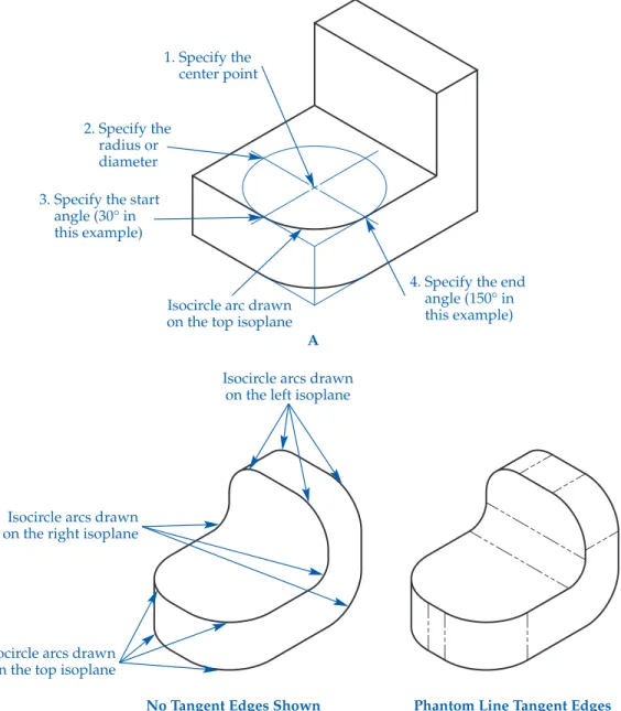
option. Then specify the location of the arc axis, or center point. Specify the radius of the arc or choose the Diameter option to specify the diameter. Enter a numerical value or pick a location along an isometric angle. Finally, select the start and end angles for the elliptical arc. See
Figure 4A-4A. The start and end angles are the angular relationships between
the center of the ellipse and the arc endpoints. The angle of the fi rst axis estab-lishes the angle of the elliptical arc. Figure 4A-4B shows additional examples of isometric arcs added to complete a mechanical part drawing. Representing tangent edges using phantom lines as shown on the right is an option, but is not common practice.
PROFESSIONAL TIP
Use Ortho mode to aid in selecting accurate start and end angles for an isometric arc.
NOTE
You can edit an ellipse or elliptical arc created using the
Isocircle option of the ELLIPSE tool just as you would any other ellipse object. However, remember that the radius and diameter of an isometric circle or arc forms along isometric angles, not the axis endpoints of the ellipse. Therefore, do not use axis endpoint grips to edit an isometric circle or arc. Use a 120° rotation angle to rotate an isometric circle or arc
Menu
Home > Draw
S U P P L E M E N TA L
M AT E R I A L S
AutoCAD
and Its Applications
B A S I C S
S t uden t Web Si t e
Chapter 4
Figure 4A-4. A—The steps required to construct an isocircle arc on the Top isoplane. B—Additional isometric arcs added to the Top, Left, and Right isoplanes.
Isocircle arcs drawn on the left isoplane
Isocircle arcs drawn on the right isoplane
Isocircle arcs drawn on the top isoplane
No Tangent Edges Shown Phantom Line Tangent Edges B
4. Specify the end angle (150° in this example) 1. Specify the center point 2. Specify the radius or diameter 3. Specify the start
angle (30° in this example)
Isocircle arc drawn on the top isoplane
S U P P L E M E N TA L
M AT E R I A L S
AutoCAD
and Its Applications
B A S I C S
S t uden t Web Si t e
Chapter 4
Start a new drawing for each of the following objects using a decimal-unit isometric template that includes active isometric grid and snap modes. If you do not have a template with these characteristics, create a template now. Set the grid to display as a pattern of dots on the screen. Change the isoplane orientation appropriately as you work to draw on each isometric plane.
1. Draw an isometric part view similar to the drawing shown below using dimensions of your choice. Save the drawing as ACT4A-2.
2. Draw an isometric part view similar to the drawing shown below using dimensions of your choice. Save the drawing as ACT4A-3.
(Continued.)
S U P P L E M E N TA L
M AT E R I A L S
AutoCAD
and Its Applications
B A S I C S
S t uden t Web Si t e
Chapter 4
3. Draw an isometric part view similar to the drawing shown below using dimensions of your choice. Save the drawing as ACT4A-4.
4. Draw an isometric part view similar to the drawing shown below using dimensions of your choice Save the drawing as ACT4A-5.