Wright State University Wright State University
CORE Scholar
CORE Scholar
Browse all Theses and Dissertations Theses and Dissertations
2019
LLVM-IR based Decompilation
LLVM-IR based Decompilation
Ilsoo Jeon
Wright State University
Follow this and additional works at: https://corescholar.libraries.wright.edu/etd_all
Part of the Computer Engineering Commons, and the Computer Sciences Commons
Repository Citation Repository Citation
Jeon, Ilsoo, "LLVM-IR based Decompilation" (2019). Browse all Theses and Dissertations. 2136.
https://corescholar.libraries.wright.edu/etd_all/2136
This Thesis is brought to you for free and open access by the Theses and Dissertations at CORE Scholar. It has been accepted for inclusion in Browse all Theses and Dissertations by an authorized administrator of CORE Scholar. For more information, please contact [email protected].
LLVM-IR based Decompilation
A thesis submitted in partial fulfillment
of the requirements for the degree of
Master of Science in Computer Engineering
by
Ilsoo Jeon
B.S.C.S., Wright State University, 2015
B.S., Wright State University, 2015
2019
Wright State University GRADUATE SCHOOL
April 25, 2019 I HEREBY RECOMMEND THAT THE THESIS PREPARED UNDER MY SUPER-VISION BY Ilsoo Jeon ENTITLED LLVM-IR based Decompilation BE ACCEPTED IN PARTIAL FULFILLMENT OF THE REQUIREMENTS FOR THE DEGREE OF Master of Science in Computer Engineering.
Meilin Liu, Ph.D. Thesis Director
Mateen Rizki, Ph.D. Chair, Department of Computer Science and Engineering Committee on Final Examination Junjie Zhang, Ph.D. Krishnaprasad Thirunarayan, Ph.D. Adam R. Bryant, Ph.D. Barry Milligan, Ph.D.
ABSTRACT
Jeon, Ilsoo. M.S.C.E., Department of Computer Science and Engineering, Wright State University, 2019.LLVM-IR based Decompilation.
Decompilation is a process of transforming an executable program into a source-like high-level language code, which plays an important role in malware analysis, and vulner-ability detection. In this thesis, we design and implement the middle end of a decompiler framework, focusing on Low Level Language properties reduction using the optimization techniques, propagation and elimination. An open-source software tool,dagger, is used to translate binary code to LLVM (Low Level Virtual Machine) Intermediate Representation code. We perform data flow analysis and control flow analysis on the LLVM format code to generate high-level code using a Functional Programming Langauge (FPL), Haskell. The result code generated by our decompiler framework is compared with the samplesource code to verify the correctness of the decompiler framework.
Contents
1 Introduction 1
2 Background 3
2.1 Intermediate Representations . . . 3
2.2 Data Flow Analysis . . . 5
2.2.1 Static Single Assignment . . . 7
2.3 Control Flow Analysis . . . 7
2.4 Decompilation. . . 8
3 Methodology 10 3.1 Dagger and Preprocessing . . . 11
3.2 Propagation . . . 14
3.2.1 Idiom . . . 14
3.2.2 Variable . . . 23
3.3 Elimination . . . 26
4 Evaluation 28 4.1 Binary Translation and Preprocessing . . . 29
4.2 Propagation . . . 32
4.2.1 Idiom Detection . . . 32
4.2.2 Variable Propagation . . . 36
4.2.3 Double Precision and Naming Variable . . . 37
4.3 Elimination . . . 40
4.4 HLL Conversion and Program’s Completeness. . . 42
5 Case Study 45 5.1 Single Basic Blocks . . . 45
5.2 Conditional Statements . . . 51
6 Conclusion 58
Bibliography 61
Appendix 65
A Source Code of Algorithms 66
A.1 Haskell Source code for Algorithm 1:BINARYOP . . . 66
A.2 Haskell Source code for Algorithm 2:BITWISEOP . . . 67
A.3 Haskell Source code for Algorithm 3: IDIOM . . . 68
A.4 Haskell Source code for Algorithm 4:PROPAGATION . . . 69
List of Figures
2.1 Example ofDUandUDchains . . . 6
2.2 Comparison of Compiler and Decompiler . . . 8
3.1 Decompiler Process Diagram . . . 10
3.2 Example of Idiom Detection and Propagation . . . 14
3.3 Binary Idiom Propagation in LLIR . . . 15
3.4 Bitwise Idiom Propagation in LLIR . . . 18
3.5 Example of AND i16%vj,−2M . . . 18
3.6 Example of Variable Propagation . . . 23
3.7 Example of Elimination . . . 26
5.1 Single Basic Block, Compound Assignment case . . . 46
5.2 Increment and Decrement . . . 46
5.3 Single Basic Block, Using Bracket case . . . 47
5.4 Numeric Variables Type Conversion from Short to Long . . . 48
5.5 Numeric Variables Type Conversion from Float to Double . . . 49
5.6 Char Type Variable 1 . . . 49
5.7 Char Type Variable 2 . . . 50
5.8 Char Type Variable 3 . . . 50
5.9 Conditional Statement, If Statement . . . 51
5.10 Conditional Statement, If and Else Statement with Equal condition . . . 52
5.11 Control Flow Graph of Figure 5.10 and its Block Order . . . 53
5.12 Conditional Statement, If and Else Statement with None Equal condition . . 53
5.13 Conditional Statement, If, Else-If Statement . . . 54
5.14 Conditional Statement, Switch Statement . . . 55
5.15 Conditional Statement, If Else and Switch Statement . . . 56
List of Tables
2.1 HLL and LL Comparison . . . 4
List of Code
4.1 Result ofdaggerbinary translated, LLVM Low-Level IR Code . . . 294.2 Result of PreProcessing initial Low-level Intermediate Representation (LLIR) 30 4.3 IR Code output Summary afterdaggerand PreProcessing . . . 31
4.4 ExamplesampleRegister List . . . 31
4.5 ExamplesampleVariable List . . . 31
4.6 LLVM Low-Level IR code before the Idiom Phase . . . 33
4.7 IR Code after Idiom Conversion . . . 34
4.8 UpdatedsampleVariable List after the Idiom Detection . . . 34
4.9 IR Code output Summary after Idiom Detection . . . 35
4.10 IR Code after Propagation Phase . . . 36
4.11 IR Code output Summary after the Variable Propagation . . . 37
4.12 objdump Disassembled Code . . . 38
4.13 objdump Disassembled .rodata section . . . 38
4.14 IR Code after Naming Varaibles and Reading Double Precision . . . 39
4.15 IR Code output Summary after the Variable and Percision Conversion . . . 39
4.16 IR Code after Elimination Phase before removing registers’ statement . . . 40
4.17 IR Code after Elimination Phase without registers’DEFandUSEstatements 41 4.18 Overall Program Summary . . . 42
4.19 High-level Langauge (HLL) Transformation Result . . . 44
5.1 HLLC of Source 5.2 . . . 46 5.2 Original Code of HLLC 5.1. . . 46 5.3 HLLC of Source 5.4 . . . 46 5.4 Original Code of HLLC 5.3. . . 46 5.5 HLLC of Source 5.6 . . . 47 5.6 Original Code of HLLC 5.5. . . 47
5.7 IR code of Figure 5.3 after Idiom Detection and Conversion. . . 47
5.8 HLLC of Source 5.9 . . . 48
5.9 Original Code of HLLC 5.8. . . 48
5.10 HLLC of Source 5.11 . . . 49
5.11 Original Code of HLLC 5.10 . . . 49
5.12 Change of variable typeain Figure 5.5’s Idiom IR code . . . 49
5.13 HLLC of Source 5.14 . . . 49
5.14 Original Code of HLLC 5.13 . . . 49
5.15 IR code after the Elimination Phase for Figure 5.6 . . . 49
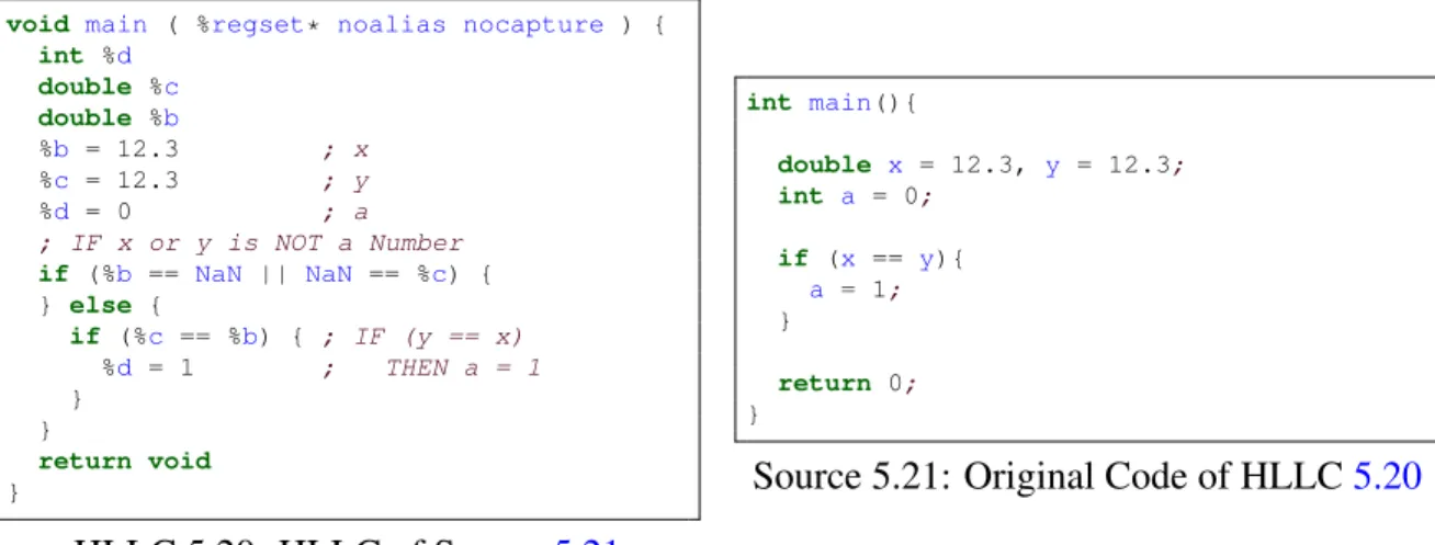
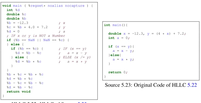
5.16 HLLC of Source 5.17 . . . 50 5.17 Original Code of HLLC 5.16 . . . 50 5.18 HLLC of Source 5.19 . . . 50 5.19 Original Code of HLLC 5.18 . . . 50 5.20 HLLC of Source 5.21 . . . 51 5.21 Original Code of HLLC 5.20 . . . 51 5.22 HLLC of Source 5.23 . . . 52 5.23 Original Code of HLLC 5.22 . . . 52 5.24 HLLC of Source 5.25 . . . 53 5.25 Original Code of HLLC 5.24 . . . 53 5.26 HLLC of Source 5.27 . . . 54 5.27 code of HLLC 5.26 . . . 54 5.28 HLLC of Source 5.29 . . . 55 5.29 Original Code of HLLC 5.28 . . . 55 5.30 HLLC of Source 5.31 . . . 56 5.31 Original Code of HLLC 5.30 . . . 56 5.32 HLLC of Source 5.33 . . . 57 5.33 Code of HLLC 5.32 . . . 57
A.1 Source Code of Binary Idiom . . . 66
A.2 Source Code of Handle Bitwise Idiom . . . 67
A.3 Source Code of Detecting Idiom . . . 68
A.4 Source Code of Propagation . . . 69
Chapter 1
Introduction
Adecompileris a reverse engineering tool which transforms a machine code into a High-level Langauge(HLL) formatted code, which plays an important role in malware analysis. The goal of decompilation is to build an easily readableHigh-level Language Code (HLLC)
without any modifications or changes in the program behaviour typically to support static analysis. It is most useful when the source code ofa program is unavilalbe, in the case of malware analysis.
A debugger and dissembler are great tools for dynamic and static analysis for reverse engineering; it shows both control flow and data flow of the program and gives an idea on the program’s semantic and behaviour. On the other hand, using assembly code for static analysis requires knowledge in architectures and is expensive; a decompiler with accessible intermediate representation code is practical to save time for analysis.
Decompiler has been around since 1960s [29, p. 1]; almost every current decompiler supports 32-bit architectures, and some of them additionally cover 64-bit architectures as well. However, many open-source ones either do not support 64-bit, or the result of decom-piler still contains low-level instruction(s) or registers which do not belong to high-level language code.
focus-ing onLow-level Language (LL) properties reduction using the optimization techniques, propagation and elimination. Both optimization techniques are frequently used during the data flow analysis; propagation supports feasible code elimination which removes unnec-essary statements or unreachable blocks. Thus, they remove LL statements and leave us with a IR code withHLLsemantics.
Since our focus is design of middle end analysis of the decompiler framework, we use the open-source translator, dagger, to transform a binary code (or a machine code) to
Intermediate Representation (IR) code, i.e., the LLVM (Low Level Virtual Machine) In-termediate Representation code. Then, to support static analysis and program verification with mathematical proof, we use Haskell to design the decompiler framework. We modify propagation and elimination techniques to work with the result LLVM intermediate repre-sentation code after binary translation. Finally, we edit control flow analysis technique to generate source-like high-level language code. The result code generated by our decom-piler framework is compared with thesamplesource code to verify the correctness of the decompiler framework.
Additional information on decompiling process and intermediate representation are described in Chapter 2, including brief summary on data flow and control flow analysis. Our methodology, illustrated in Chapter 3, proposes the modified middle end including the optimization techniques, propagation and elimination, for decompilation; and then, we use a samplebinary code, originally written in C languages, to evaluate the optimization techniques, propagation and elimination. The result code is compared with the sample
source code, in Chapter4. Finally in Chapter6, we summarize our thesis work and discuss the limitation of our research and future work to improve it.
Chapter 2
Background
Source codeis a code originally written by a programmer1, typically using human-readable programming languages [26], such as C and Python; whereas, a code written for a elec-tronic devices to run and execute is calledMachine Code (MC).
In this chapter, we present the basic concepts related to the techniques used in this thesis. In Section 2.1, intermediate representation languages are introduced, and major analysis will be performed in intermediate representation language to recover and generate source-like formatted code from MC. In the thesis, we choose to use LLVM (Low Level Virtual machine) intermediate representation. Two analysis methods data flow analysis and control flow analysis are introduced in Section 2.2and Section 2.3. Then, decompilation process is described in Section2.4.
2.1
Intermediate Representations
Intermediate Representation(IR), also known as intermediate language, is a representation used in compiler betweenHigh-level Langauge(HLL) (source programming language) and
1GNU and FSF argue that ”Obfuscated ‘source code’ is not real source code and does not count as source
Low-level Language(LL) (target machine instruction language)). The purpose ofIRis to make a compiler retargetable from oneHLLto multiple architectures and to perform code analysis and optimization during compilation without changing program behaviour.
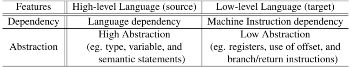
A single source code can result in differentMCwith the same behaviour, depending on hardware architectures, like Instruction Set Architecture (ISA) (see Table 2.1); while transformingHLLsource code to a targetMC, compilers use a universal language, IR, to support multipleLL.
Features High-level Language (source) Low-level Language (target) Dependency Language dependency Machine Instruction dependency
Abstraction
High Abstraction Low Abstraction
(eg. type, variable, and (eg. registers, use of offset, and semantic statements) branch/return instructions)
Table 2.1: HLL and LL Comparison
Thus,IRneeds to have some abstraction but is still able to be implemented in machine-like instructions; in the article“The increasing significance of intermediate representations in compilers” [6], Chow points out the following important features of intermediate lan-guages: completeness, semantic gap, neutrality, programmable, extensible, simplicity, pro-gram information, and analysis information.
In the thesis, we choose to useLLVM(Low Level Virtual Machine) intermediate rep-resentation for multilingual supports [18] through active open projects2. Also, it has some features [6] that are suitable for our flow analysis and source-like code generation, illus-trated as follows:
• LLVM IR has 31 opcode [19] (simplicity) and is able to write a code and modify it
(programmable)3
• The representation uses low-level instruction set and memory models, but contains high-level abstraction, such asswitch, except forclass, inheritance, and exception
2LLVM Projecthttp://llvm.org/ProjectsWithLLVM/,Open Projecthttps://llvm.org/OpenProjects.html 3able to use command to convert or execute it, seehttps://llvm.org/docs/CommandGuide/
handling[19]. However, the syntax is not related to any specific hardware or source-languages (Independency)
• It uses general type-based system which is free from predefined fixed-sized definition in architecture andHLL. For example,intcan refers to an integer with different bit-size depending onHLLandLL, where as LLVM usesi#format to indicate #-bit size of integer. This type system is helpful for pointer analysis and data transformation. • Use ofStatic Single Assignment Form(Subsection2.2.1) andcontrol flow graphwith
basic block(Section2.3) makes analysis easier to apply compiler optimization tech-niques, in Chapter3
2.2
Data Flow Analysis
Data Flow Analysis (DFA)is a technique to observe variables’ information, how they are defined and used in the program. Primary operation, in decompiler, is converting LLIR
code intoHigh-level Intermediate Representation (HLIR)code [9]; we useDFAdata struc-ture for our compiler optimization techniques. Here is a list of terms and definition of data structures that we use in this thesis:
• Left Hand SideandRight Hand Sideindicate an expression on a left side and the one
on a right side of an equation, typically, centered on equal sign (=or:=).
• A variablevisdefinedwhenvis on the left hand side of a statement. However, in high-level language,v is defined when a memory-location is assigned to it. For instance, in C, ‘int x;’ is not an equation statement but a memory address is assigned to the variable
x.
• Definitionof a variable v is an expression on the right side of a statement, definingv.
• A variable v isused whenv is either on the right side of a statement or appears on a non-equation statement (eg.return v). For example, given a statements:x=y+5,
yis used ins. It is denoted asUSE(y) = [s] OR[x=y+ 5] andIN-USE(s) =y.
• Define-Use chainis a list (or a table) storing a statement which defines a variable and
a list of statement where the variable is used, denotedDU(v) = (DEF(v),USE(v)).
• Use-Define chain is a list (or a table) storing a statement using a variable and a list
of a possible definition(s) of the variable, denotedUD(v) = (current statement usingv, [DEF(v)]) or (current statement usingv, [statement of DEF(v)]).
s1: x = α s2: if(x > β) s3: then s4: x = 2 s5: y = 1 s6: else s7: y = 0 s8: z = x + y DU(x) = (α, [s2,s8]), (2, [s8]) DU(y) = (1, [s8]), (0, [s8]) DU(z) = (x+y, []) UD(x) = (s2,α) or (s2,s1) UD(x) = (s8, [α, 2]) or (s8, [s1,s4]) UD(y) = (s8, [1, 0]) or (s8, [s5,s7]) Figure 2.1: Example ofDUandUDchains
• For i, j ∈ N, i < j, let a variablev is defined at a statementsi (denotedvsi). We say
thatDEF(vsi) iskilledat a statementsj which redefined the variablev.
• A variablev is stated as alivevariable at a program point (or a statement)p, ifv will be used in the future without being killed.
• A variablev is called, adeadvariable, at a program point (or a statement) p, ifv will not be used in the future.
2.2.1
Static Single Assignment
Static Single Assignment Form (SSA) is a intermediate representation form where every variables are defined only once; the variable is renamed when the variable’s definition is reassigned. For instance, a variable x is not renamed the initial declaration, but any re-declaringxis renamed asx1,x2,x3, etc. sequentially.
SSAmakes program analysis more feasible [29, section 4.2-4.3] since there is no need to worry about killed variables and change of definitions. In our thesis, we use the static single assignment format in LLVM IR to track variables to modify and delete duplicated information in a IR code, usingDUandUDchain.
2.3
Control Flow Analysis
Control Flow Analysis (CFA)is another analysis technique, illustrating the program’s run-ning path. It is used to detect and define loop, conditional (or unconditional) statements, function(s), and functional call and return by constructionControl Flow Graph (CFG). To draw aCFG, we starting from diving code intobasic blocksbased on terminator instruc-tions.
Basic Block (BB)is a linear sequence of instructions (or statements) which runs straight (from top to bottom) without any branching interrupt; branching only occurs at the top of the block (from predecessor), calledentry point, and at the end of block, calledexit pointto pass the program control to another basic block, successor. EveryBBends with either con-ditional (or unconcon-ditional) instruction, functional call and return, or indirect tail or pointer call [17, p. 111]; the last instruction of each basic block is called terminatorinstruction4. After the block of code is divided into basic blocks,CFAis assigned to find direct prede-cessor(s) and sucprede-cessor(s) of each blocks, depending on the terminator instructions. The
CFGis provided to rearrange theIRcode and generate the source-likeHLLC.
2.4
Decompilation
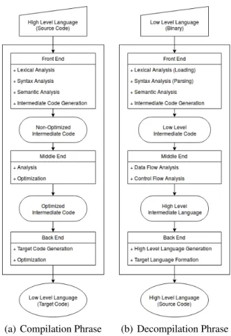
Acompileris a program that translates source code (written in HLL) to a target language (Low-level Language Code (LLC)) for a processor to read and run. In contrast to a com-piler, a program translating aLLCto aHLLCis called adecompiler. Since the decomiler reverses the compiling process, it has the same transforming steps as a compiler, as shown in Figure2.2.
(a) Compilation Phrase (b) Decompilation Phrase
Figure 2.2: Comparison of Compiler and Decompiler
The first step of a decompiler is the front-end that performs code analysis on LLC, typicallyMC. The objective of this phase is constructing aCFGand generating a machine-independent intermediate representation code, called LLIR. LLC has a strong machine dependency such as operator instructions and data formats. Different architectures use dif-ferent operator instructions and data formats than others; the front-end runs two linguistic
analysis to remove machine dependency from the code [8, Ch 4]: syntax analysis, and
semantic analysis.
• syntax analysis, also called parsing, follows the control flow and create a CFG; it generatesLLIRand passes it to semantic analysis step.
• semantic analysisdivides a block of code into basic blocks and doesidiom analysis,
propagationandnon-referred block elimination.
After the linguistic anlaysis, the next phase ismiddle-end which handlesDFA (Sec-tion2.2) andCFA(Section2.3). In a decompiler, the primary goal ofDFAis transforming the output of front-end,LLIR, into aHLIRcode forHLLCgeneration (see Figure2.2(b)). Low-level concept symbols, flags and registers, need to be removed as follow [9]:
• Applying use/define chain analysis on the conditional branch instructions, register
flags are removed and abstract expression (comparison symbols, like <, or ==)
statement is edited.
• Using backward-flow (or bottom-top) analysis, the content of a defined register is substituted for the register; it is calledforward substitution.
Once theLLIRcode has no more low-level symbols,CFAis applied to convert low-level instructions into high-low-level abstracted statements,HLLstructures. It forms a BBand observes predecessors/ successors. Thus,if-else, switch, for/while/repeat loops are used instead of conditional/unconditional branching and multi-branching in-structions; it results aHLIR.
Finally, a decompiler takes theHLIRand translates it into a C-like programming lan-guage code, in theback-endstage. After the code conversion, different decompilers might edit the format of the result HLLcode, as an additional option [9]; formats includes re-naming functions, variables, branching label, adding related libraries (e.g. <stdio.h> in C) statements, and more. In the end, the decompiler outputs a source-likeHLLCwhich is more suitable to read for static analysis.
Chapter 3
Methodology
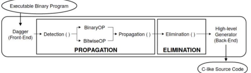
In this chapter, we first illustrate how to use the open-source program dagger[30] for bi-nary translation and apply two common compiler optimization techniques,propagationand
elimination, to convert binary code toHLLC. As introduced in Section2.4, decompilation has three major passes (front-end, middle-end, and back-end). Section3.1 introduces the front-end phase, and it runs the dagger program and preprocesses LLIR contents before code analysis.
Then, we illustrate the middle-end stage, which applies the optimization techniques,
propagationandelimination, to generateHLIRcode fromLLIR(as shown in Figure3.1).
Propagation(as illustrated in Section3.2), converts a single variable or set of instructions into another form. Elimination(explained in Section 3.3) removes any unnecessary state-ments such as dead-variables (or dead-statestate-ments).
3.1
Dagger and Preprocessing
Dagger [24] is an open-source binary translator which transforms binary code to inter-mediate representation code. It is based on LLVM IR, and uses an MC Layer API (open project in LLVM), to convert a binary code to anLLIRcode. In this project, we use dag-geras our front-end phase to obtain the intermediate representation code (as illustrated in Section2.4).
After applyingdagger on the input binary code, the output LLIRcode includes reg-isters and functions from the following Executable and Linkable Format (ELF) attribute sections [15].
.plt (Procedure Linkage Table) It is an offset table for dynamically linked functions, including ones from a standard library.
.text Contains a list of the functions from user’s executable code, including functions for setting up registers (pointers) and dynamic objects.
.init Runtime initial code block which runs before the user’s executable code (e.g.
mainin C); it includes dynamic objects.
.fini Runtime terminal code block which runs after the user’s executable code; it includes dynamic objects.
Description 3.1: Attribute functions in disassembled code
Although the attribute functions are critical to analyze and understand a program’s behaviour, we only focus on handling non-attribution functions to reduce the size ofLLIR
content since they are not a part of typical source code. Based on the outputs of multiple test code segments, attribute functions are located after the @MAINfunction in thedagger
IR. We make an assumption that library functions -including static and dynamic linked libraries- and user-typed functions are listed before the defining @MAINstatement. Thus, the preprocessing method keeps the functions defined before thedefine @mainline and discards the rest of the codes.
In addition to attribute functions, unlike theHLLC, IR contains the following format-ted blocks at every function, starting at an address(#):
entry fn # First block which runs when the function is called. It initialises necessary register pointers for the function, such as %IP (instruction pointer) before the executable block(s). Also, calledentryblock in this paper.
exit fn # Last block runs right before the function exit to restore initial registers’ value (before the entry initialisation). Also, calledexitblock in this paper.
bb # (a functions initial block) Immediate successor of entry fn # block. It is a part of an executable code which holds high-level information, like idiom (Section3.2.1). Also, calledinitialblock in this paper.
bb #n General block(s) which is a part of executable code.
Description 3.2: Different type of basic blocks in a function
Even thoughentry fn #andexit fn # are not directly part of a source code, they ini-tialise and set up the register and pointer values, for the function. They are essential for pointer analysis and analysis on function call(s) and return(s)1; we do not delete them.
Furthermore, the output of dagger keeps track of the value of the registers, like a disas-sembled code (fromobjdumpor IDA Free), and it tracks all 8-bit, 16-bit, 32-bit, and 64-bit registers by converting the type of variables (e.g. from 32-bit integer to 16-bit integer). Since 32-bit or 64-bit architectures are more common, we make assumption where 8-bit and 16-bit registers are not useful and unnecessary. Thus, our preprocessing method reads every line and eliminates any statement which defines or uses 8-bit or 16-bit registers; this also reduces the size of the workload.
Meanwhile, we split the IR-code into a chunk of functions and create two lists,vList
andpList, with some categories (see List3.3). The middle-end optimization program reads each function’s IR-code and adds defined variables and itsDEFinformation to the list; these tables function as a lookup table for variables during the code analysis.
1The project does not cover the pointer analysis and calling functions; however, they are for a future
• vList: List of defined variables (eg. x=ANDi32a,b)
variable defined variable x
vtype type of variable i32
instruction instruction/operator of a statement AND
state DEF(variable) AND i32a,b
• pList: List of defined registers (eg.esp3=ADDi32esp1,α)
rname defined register variable esp3
rbase 1st operand, register variable before SSA format esp1
ridx 2nd operand, a numeric value (default = 0) α
rstate DEF(register) ADD i32esp1,α Description 3.3: Description for defined variable and registers lists
Since general variables are defined and named as unique numbers inssaformat (eg. %1, %2, %3, ...); we can parse each individual code line to store variables and registers in the list. However, we backtrack each register to find the base register inSSAformat in LLVM-IR.
For example, registers are numbered after their base variable (eg. %RSP 0 is derived from the base %RSP register) in SSA form. %RSP 1 can hold the same value as %RSP (%RSP 0 := %RSP 1 := %RSP), or it can hold a different value (%RSP 1 := %RSP 0-8 where %RSP 0 := %RSP-4). The scanning process attempts to define the variable with the base register. So, in this case, %RSP 1 := %RSP-4-8 ⇒ := %RSP-12, and this new information gets stored atpListas arstate.
In summary, binary transformation and the preprocessing output a modified LLIR, such that theLLIR has no 8-bits or 16-bits registers or attribute functions; also, it creates two lists,vListandpList.
3.2
Propagation
Propagationis an optimization technique to substitute a variable with another, especially for redundant information (or variable). A declared variable is reusable or is able to be restated inHLLC, but MCneeds to repeatedly load and store a variable from memory as necessary. AlthoughIRis notMC, binary translation in thefront-enddoes not remove ma-chine properties. So, LLVMLLIRcode contains machine-like instruction syntax, including loadandstoreoperators, and registers;propagationtechnique is used to transform re-maining machine properties in IRcode into HLL, especially in the following conditions:
idiomand redundant variable.
3.2.1
Idiom
Binary code is a list of instructions (or operations) which form a program; it is hard to know the semantics of an individual instruction by itself. However, a sequence of instructions can give us more information about the program semantics and behaviour; these sequence of instructions are calledidioms.
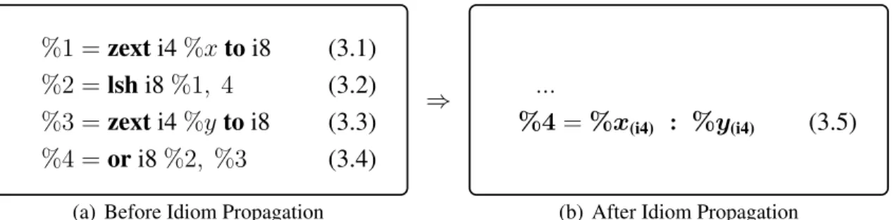
The code shown in Figure 3.2(a) is a LLIR code in LLVM format, converted from a binary program. There are four sequential instructions zext, lsh, zext and or in statement3.1,3.2,3.3and3.4respectively.
%1 =zexti4%xtoi8 (3.1)
%2 =lshi8%1, 4 (3.2)
%3 =zexti4%ytoi8 (3.3)
%4 =ori8%2, %3 (3.4)
(a) Before Idiom Propagation
⇒ ...
%4=%x(i4) : %y(i4) (3.5)
(b) After Idiom Propagation
Figure 3.2: Example of Idiom Detection and Propagation
vari-able, and lsh performs a logical left shift on %1 four times. Statement (3.1) and (3.3) do not change the value, but statement (3.2) itself is an idiom and can be converted to
%2 =muli8%x, 16, without changing the program semantics or behaviour.
In addition, evaluating all four statements, we can tell%4is an 8-bit integer which has
%xvalue in high 4-bit and%y value in low 4-bit. In statement3.1, %1holds value 8-bit integer0000 : %xi42. Then,lshoperator performs left shift on%1, resulting%2←%xi4 :
0000. Next, third statement results%3 ←0000 : %yi4, similar to statement3.1. Performing
bit-wise or on %2 and %3, statement 3.4 is the same as saying (%4 ← xi4 : 0000 or
0000 :yi4)⇒(%4←xi4 :yi4).
Therefore, the sequence of four instructions [zext, lsh, zext, andor], from Figure 3.2(a), is an idiom which can be converted into a single statement with a bitwise concatenation colon (:). This type of conversion is called idiom propagation (see Figure3.2).
Binary Idiom
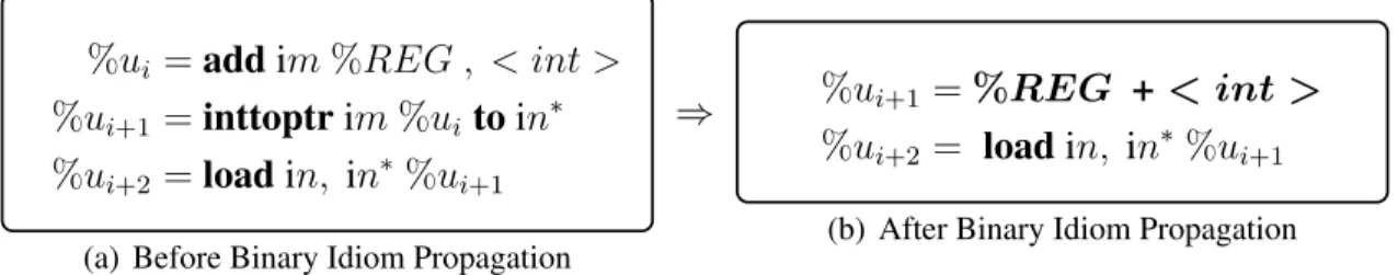
IndaggerLLIR, there are two common idioms, [add(sub), inttoptr, load(store)] and [zext, and, or]. First [add, inttoptr, load] idiom is calledBinary-idiom; it is used to get a memory location to load data from the memory location into variable or to store a value in the memory location. In Figure3.3, we present a generalized binary-idiom inLLIRform from the result of dagger.
%ui =addim%REG , < int >
%ui+1 =inttoptrim%ui toin∗
%ui+2 =loadin, in∗ %ui+1
(a) Before Binary Idiom Propagation
⇒ %ui+1 =%REG + < int > %ui+2 = loadin, in∗ %ui+1
(b) After Binary Idiom Propagation
Figure 3.3: Binary Idiom Propagation inLLIR
NOTE: [] indicates other additional information in LLVMloadandstoreform 2:is a Bitwise Concatenation Instruction
In this idiom, add instruction requires to have either a register pointer or a register variable (%REG) (e.g. %eax or %rbp) and an index of an integer type. Since it has
%REGand an index, we can convert theLLIRformatted statement into aHLLformat to help generateHLLcode (eg. x=adda, b7→x=a+b).
Next,inttoptrinstruction converts the register value type to a pointer for the next load statements. Although the type is changed, the value itself remains the same. We define Left Hand Side (LHS) variable %ui+1 as the HLL formatted add statement (see Figure3.3(b)) and remove%uivariable and its statement.
The optimization program is aware of the binary-idiom when it encounters a statement with anaddinstruction during the scanning process. Althoughaddoperator might be used in a different idiom or for general computation, the binary-idiom can be identified sicne one of the operand must be a register (eg.%REG) to be a part of a binary-idiom, followed by an inttoptroperator statement. Therefore, when theaddoperator is found, we convert the
LLIRstatement into theHLLformat (eg.addv, 57→v+ 5), and then, we call BINARYOP function.
Algorithm1, is a designed to performs idiom propagation when the sequence of state-ments is BINARYOP. BINARYOP, in Algorithm1, is a sub-function which handles
binary-idioms; it determines whether theadd statement is a part of a binary-idiom, based on the operator next statement, nextLine. If the statement is a part of the idiom, the function performs idiom propagation, as shown in Figure3.2(b).
In Algorithm 1, the BINARYOP function receives aLHSvariable and a Right Hand Side (RHS) statemen ofadd statement, next-line statement, ad a list of variables, vList. First of all, it extractsLHSvariable from the next-line, and callednv; it is equivalent to the
%ui+1 variable from the binary-idiom example. Then, it checks, if the LHSvariable and
RHSdefinition from next-line fit the binary-idiom format (line8of Algorithm1).
If the next-line fits the pattern of a binary-idiom, it removes the current LHS add variable from the list since it is defined forinttoptrstatement, as a part of the idiom.
It writes a new line, called addLine, such that DEF(nv) is the add right-side definition (line10of Algorithm1) and returns the newaddline, along with an updated variable-list.
Algorithm 1Binary operation with register pointer
1: caller: DETECTIDIOM(Algorithm3)
2: Input:
v :=LHSvariable ofaddstatement
addHLL:=convertedaddstatement in [ptr+k]HLLformat fork ∈Z
nextLine:=next line ofaddstatement
vList:=List of defined variable (generated during the preprocess, Section3.1)
3: Output:
addLine:=idiom-propagatedDEF(ui+1) OR unmodifiedDEF(ui)addstatement
nextLine:=an empty string OR an unmodifiedinttoptrstatement
vList:=updated variable list
4: functionBINARYOP(v,addHLL,nextLine,vList)
5: vcurrent ←v data fromvList
6: nv ←nextLineLHSvariable
7: vnext ←nvdata fromvList
8: ifnvnot NULL &nextLineoperator isIntToPtrthen
9: removevcurrent fromvList
10: addLine←CONCAT(nv, “=”,addHLL)
11: setvnext’s instruction to Empty-String and state to beaddHLL
12: vList←updatevnext
13: nextLine ←“”
14: else
15: addLine←CONCAT(v, “=”,addHLL)
16: setvcurrent’s instruction to Empty-String and state to beaddHLL
17: vList←updatevcurrent
18: end if
19: return(addLine,nextLine,vList)
20: end function
However, if the next-line is not a part of the idiom, it updates the definition of current variable v to be the input RHS statement (line 15) and returns the updated v statement, unmodified next-line statement, and the updated variable-list.
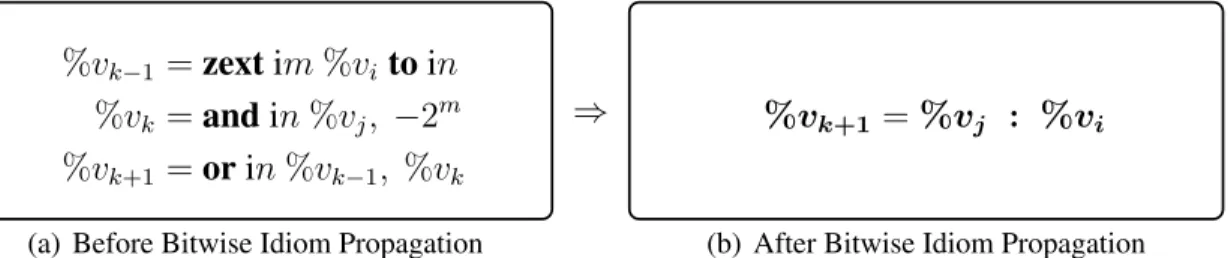
Bitwise Idiom
The second idiom, the [zext, and, or] idiom is a bit-wise operating idiom which is similar to the idiom example Figure3.2. It is used to save data in extension registers%xmm ,%ymm, or%zmmfor later use; the set of instructions is typically followed by astoreline. Below Figure3.4shows the general formatted structure of theBitwise-Idiom.
%vk−1 =zextim%vi toin
%vk =andin%vj, −2m
%vk+1 =orin%vk−1, %vk
(a) Before Bitwise Idiom Propagation
⇒ %vk+1 =%vj : %vi
(b) After Bitwise Idiom Propagation
Figure 3.4: Bitwise Idiom Propagation inLLIR
First zext instruction, in Figure 3.4, adds zeros in front of the vi integer variable
to extend the size of it. Suppose the size of the variable was m-bit, zext adds(n−m)
number of zeros to convert the value to a n-bit integer. We can use colon operator to re-write the statement as follow:%vk−1 = 0(n−m) : %vi.
Independent from the first zext statement, the second statement performs bitwise and operation in %vj and −2m. Any integer of −2m is in 111...11000...0 format; and
operator with−2m zeros the lastm-bit of variables.
Let%vj = 53AChex = 0101 0011 1010 1100bin.
Given−2poperand Result after: ANDi16 53AC,−2p −21 =−2 = 1111 1111 1111 1110bin ⇒ 0101 0011 1010 1100 (3.6)
−22 =−4 = 1111 1111 1111 1100bin ⇒ 0101 0011 1010 1100 (3.7)
−24 =−16 = 1111 1111 1111 0000bin ⇒ 0101 0011 1010 0000 (3.8)
In Figure 3.5, we compute 16-bit AND 0x53AC, −2p, wherep is set to be different
values. For givenp= 1,2,4, each result value consists of first (16-p)-bit value of 0x53AC and zeros for remaining lowerp-bits. As a result,%vj .&. −2m keeps the highest(n−m)
-bits from%vj and converts the lowm-bits to 0s (denoted by%vk = %vj : 0m).
The last instruction in the bitwise-idiom has an or operator, denoted by vk−1.|.vk.
From previous statements, we know that the size ofvk−1 andvk aren-bit; we can say that
vk−1.|.vk ⇒ (0(n−m) : vi) .|. (vj : 0m)where the sizes of high (n −m)and low m bits
match one to another. Therefore, we can convertorinstruction intocolon (:)operator, denoted byvk+1 =vj :vi, using idiom propagation.
In contrast to the binary-idiom, BINARYOP, the optimization program alerts the
bitwise-idiom when it finds an and operator statement with a negative integer operand which is power of 2. Theandis not the first sequence of instructions in the idiom, but it has a no-ticeable property,−2moperand; whereas, the first instructionzextdoes not have a special feature to indicate if it is a part of an idiom or not. So, the optimization program calls the BITWISEOP function when it sees theandoperator with−2moperand.
BTWISEOP function, described in Algorithm2, determines whether the sequence of
statements is a bitwise-idiom and converts the idiom to a singlecolonstatement. Algo-rithm2takes three consecutive statements and the variable list (line2) as the input.
In Algorithm2,cLineis an instruction statement with theandoperator, and previous and next statement ofand statement are denoted bypLine andnLine. The BITWISEOP function extracts LHS variable of each statements and checks if previous and next state-ments havezextandoroperator, respectively (line8).
If the line sequence is not the [zext, and, or] idiom, it returns all the input state-ments and the unmodified list back to the caller. In contrast, if the statestate-ments fit the bitwise-idiom’s pattern, the−2m operandop
current and an operand ofzextin the previous
Algorithm 2Bitwise operation with zeros
1: caller: DETECTIDIOM
2: Input:
cLine:=AND operator withopcurrent, (−2m)
pLine/nLine:=previous / next line ofcLine
vList:=List of defined variable (generated during the preprocess, Section3.1)
3: Output:
[s1,s2,s3]:=List of sequential statements (previous, current, and next lines)
vList:=either modified or unmodified variable list
4: functionBITWISEOP(pLine,cLine,nLine,vList)
5: (pv,v,nv)←LHSvariables frompLine,cLine, andnLine
6: ifpvnot NULL ANDnvnot NULLthen
7: (vpre,vcurrent,vnext)←pv,v, andnvvariables data from thevList
8: ifZEXToperator inpLine&ORinnLinethen
9: (opcurrent, oppre)←(operand incLine, operand inpLine)
10: state←CONCAT(opcurrent, “:”,oppre)
11: newLine←CONCAT(nv, “=”,state)
12: setvnext’s instruction to Empty-String and state to bestate
13: removevpre andvcurrentfrom thevList
14: vList←updatevnext
15: return([ “”,newLine, “”],vList)
16: end if
17: end if
18: return([pLine,cLine,nLine],vList)
19: end function
After creating thecolonstatement, the function writes a statementnewLinewhere thecolonstatement becomes a definition of thenLine’sLHSvariable,nv. LHSvariable of previouszextand currentandstatements are deleted from the variable-list since there is no more use of them; information on thenvis updated.
In the end, the function returns a list of three statements (an empty string, newLine
colon statement, and an empty string) and the updated variable-list; empty strings are added to keep the space for the list of three elements. The first two statements are meant for already-scanned statement, and the third statement is for next statement to scan; the illustration details are presented in Algorithm3.
Idiom Detection
As illustrated in the previous sections, the optimization program detects idioms during the
LLIRscanning process which is performed by the DETECTIDIOM function, as presented
in Algorithm3. The purpose of the function is to read theLLIRcontent, from Section3.1, and call the corresponding sub-function, BINARYOP or BITWISEOP, for the pre-defined
idiom conversion (Section3.2).
Given a block of preprocessed IR-code and a variable list of the function, DETEC
-TIDIOMreads the code line by line. Typical line fits one of the following format (memory address of an initial function or a basic block is denoted by#addr):
Define Function define void @fn [#addr](%regset* ...) {
Block Label entry fn #addr:ORexit fn #addr:ORbb #addr:
Statement var =[M achineInstrution] ... OR [M achineInstruction] ...3 End of Function }
In Algorithm3, if a line declares a function, it parses@fn [#addr]part from the line
and sets it as a function name of current IR code (line13and14). At line16, we only care about lines withLHSvariable since our idioms are associated with variable declaration and uses. Therefore, the function looks for line with LHS variable and an add, sub), or an andoperator; then, it calls BINARYOP or BITWISEOP function. In the case of non-LHS,
block labeling, or an end of function line, we do not do anything and read next line. The DETECTIDIOMrepeats the scanning and idiom-conversion process until there is no more line to read in the current function block’s IR-codeCir. Once the entire IR-code
is read, it returns the parsed function name, idiom-converted IR-code, and the updated variable list.
Algorithm 3Detect idioms and Modify low-IR
1: Input:
2: Cir :=IR file content of some function block (translated bydagger, in Section3.1)
3: vList:=List of defined variable (preprocessed, in Section3.1)
4: Output:
5: f unctionN ame:=format: @fn [initial address of the current function]
6: Cir :=Idiom-propagated / convertedLLIR
7: vList:=Modified variable list
8: functionDETECTIDIOM(Cir,vList)
9: create variablef unctionN ame
10: initialisen←total line number ofCir
11: fori←0... ndo
12: line←Cir[i]
13: iflineis FunctionLinethen
14: f unctionN ame ←parse Function Name
15: end if
16: iflinedeclares variable (LHS)then
17: v ←LHS variable
18: iflinehasADD/SUBand Register operand (ptr)then
19: (ptr,idx)←operands (op1,op2) fromline
20: state←Convert machine-likeDEF(v) to a computational one
21: (Cir[i],Cir[i+1],vList)←BINARYOP(v,state,Cir[i+1],vList)
22: end if
23: iflinehasANDoperator and−(2bitsize)operandthen
24: (tmp,vList)←BITWISEOP(Cir[i-1],line,Cir[i+1],vList)
25: [Cir[i-1],Cir[i],Cir[i+1]]←tmp
26: end if
27: end if
28: end for
29: return(f unctionN ame,Cir,vList)
3.2.2
Variable
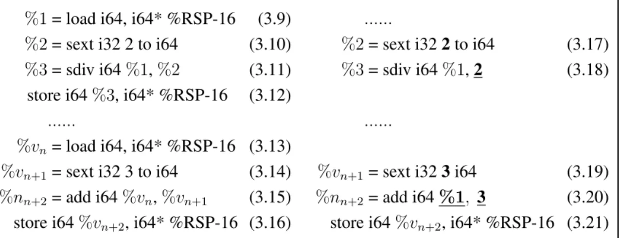
Variable Propagationis another propagation method to substitute a variable with another, especially to remove redundant information, such as repetitious memory accesses and type conversion.
In Figure3.6(a), there is a variablexat the memory location %RSP-16. The variable
xis used in division and summation; the data at the location %RSP-16 is loaded twice to two different variables (statement3.9 and 3.13) since there is no concept of variables in
Low-level Language. Thus, as marked in statement3.20in Figure3.6(b), previous variable
%vnis able to be replaced with%1using propagation.
%1= load i64, i64* %RSP-16 (3.9)
%2= sext i32 2 to i64 (3.10)
%3= sdiv i64%1,%2 (3.11) store i64%3, i64* %RSP-16 (3.12)
...
%vn= load i64, i64* %RSP-16 (3.13)
%vn+1= sext i32 3 to i64 (3.14)
%nn+2= add i64%vn,%vn+1 (3.15) store i64%vn+2, i64* %RSP-16 (3.16)
(a) Before Variable Propagation
...
%2= sext i322to i64 (3.17)
%3= sdiv i64%1,2 (3.18)
...
%vn+1 = sext i323i64 (3.19)
%nn+2 = add i64%1, 3 (3.20) store i64%vn+2, i64* %RSP-16 (3.21)
(b) After Varaible Propagation
Figure 3.6: Example of Variable Propagation
On the other hand, type declaration is essential inHLLto write a code; therefore, we need to keep the type of variables. However, most of type conversion instructions can be re-moved without changing the program behaviour, except forbitcastinstruction between an integer and floating point number. In Figure3.6(a), there is a 32-bit integer value 2 in statement3.11. Converting it to 64-bit does not change the data value; we can ignore these type conversion statements. Variables%2and%vn+1are substituted with a constant values 2 and 3, accordingly in statement3.18and 3.20since they contain duplicated information.
In our optimization program, we design a PROPAGATION function to handle the vari-able propagation to reduce the duplicated information inLLIR-code. Algorithm4 shows the propagation process in detail, and specifies the input and output of the algorithm.
Algorithm 4Propagation
1: Input:
2: Cir :=IR-code of a function after idiom-propagation (output of Algorithm3)
3: vList:=List of defined variables in the function (output of Algorithm3)
4: pList:=List of defined registers in the function (preprocessing, Section3.1)
5: Output:
6: Cir :=variable propagated function IR-code
7: vList, pList:=Propagated and modified list of general and register variables
8: functionPROPAGATION(Cir,vList,pList)
9: initialisen←total line number ofCir
10: fori= 0... ndo
11: line←Cir[i]
12: iflinehasLHSvariablethen
13: x←LHS variable from the line
14: ifxis a register variablethen
15: vx, px ←xvariable data from thevListandpList
16: iflinehascolon(:)then(eg.x=high : low)
17: rstateofpx ←stateofvx
18: pList←Updatepxinfo
19: end if
20: Cir[i]←CONCAT(x, =,px rstate)
21: replacevariable fromxwithpxrstateinCir[i+1]...[n]
22: updatevListfor anyLHSvariable change inCir[i+1]...[n]
23: else(xis General Variable)
24: switch(lineinstruction type)
25: caseconversion⇒xnew←operand oflinestatement
26: casecolon(:)⇒xnew ←low operand ofline
27: default(other instruction types)⇒xnew ←x
28: replacevariable fromxwithxnewinCir[i+1]...[n]
29: updatevListfor anyLHSvariable change inCir[i+1]...[n]
30: end if
31: end if
32: end for
33: return(Cir,vList,pList)
The main idea of the PROPAGATIONfunction is to deal with the propagation of register variables (eg. %BP) and general variables separately as we have register list, pList, in addition to the variable list,vList, from the idiom propagation.
Again, propagation is associated with variables, the function only cares for the line statement withLHSvariable; it reads the next line if the statement does not define a vari-able. However, for every line withLHSvariable, the program checks if theLHSvariablex
is a register or a general variable (line14in Algorithm4).
Assumexis a register, we get variable information from thevListand thepList. If the definition ofx invListis modified during the idiom propagation (Section 3.2.1) and contains colon (:), the function edits the rstate information of x in pList (List 3.3, Section3.1); such that, it matches to thexinformation fromvListin line16to line18.
OncexinpListis updated, we change the current statement (line20) which is built on the base register and index. Then, we substitutexwithpx rstateinIRcode; for instance,
new line statement is %RSP 1 = %RSP-12, and all %RSP 1 is replaced with %RSP-12. In the end, all of the code lines use the base variable of the currentxinstead ofSSAformatted registers.
Otherwise, if theLHSis a general variable, it checks if the statement has conversion instruction or colon. For type conversion operator, it takes its operand as a new variable
vnew in line 25; whereas, it takes low-bit operand as a vnew in colon statement (line 26).
Next, it replaces all LHS to new variable vnew in the IR and updates the variable list as
needed.
The PROPAGATION function may change the IR content and read edited lines during the process; it runs until there is no more line statement to read. In the end, the function results in edited Cir content and updated vList and pList which are more suitable for
3.3
Elimination
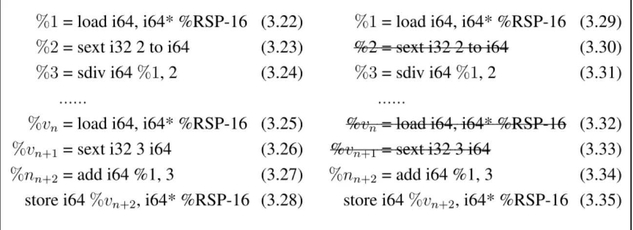
Elimination technique is applied at the end of the middle-end phases of decompilation; it cleans up code and converts LLIR code to HLIR code. The propagated LLIR code has statements with useless variables (called dead) or variables with no declaration; we delete thesedeadvariables and statements with undefined variables from the IR code. For instance, left side of Figure3.7is the output of the variable propagation from Section3.2.
Suppose variables%2, %vn, and%vn+1 are not used after the propagation, (see Fig-ure3.6). We cross out statements 3.30, 3.32, and3.33, which define dead variables,%2,
%vn, and%vn+1, as they are longer needed.
%1= load i64, i64* %RSP-16 (3.22)
%2= sext i32 2 to i64 (3.23)
%3= sdiv i64%1, 2 (3.24)
...
%vn= load i64, i64* %RSP-16 (3.25)
%vn+1= sext i32 3 i64 (3.26)
%nn+2= add i64 %1, 3 (3.27) store i64%vn+2, i64* %RSP-16 (3.28)
(a) Before Elimination
%1= load i64, i64* %RSP-16 (3.29) %2 = sext i32 2 to i64 (3.30)
%3= sdiv i64%1, 2 (3.31)
...
%vn= load i64, i64* %RSP-16 (3.32)
%vn+1 = sext i32 3 i64 (3.33)
%nn+2 = add i64 %1, 3 (3.34) store i64%vn+2, i64* %RSP-16 (3.35)
(b) After Elimination
Figure 3.7: Example of Elimination
Algorithm5 illustrates the elimination process. In Algorithm 5, we have a function called ELMINATIONwhich takes similar arguments as PROPAGATIONof Algorithm4, and a Boolean typed variable, called change, to indicate if there are any changes made in the content during the scanning process.
In contrast to the propagation techniques, elimination handles both LHS and non-LHS lines; it removes lines with dead variable v (where kUSE(v)k = 0, line 9). Also, it
Algorithm 5; this way, we do not need to read the code several time to remove USE(x )-statement while we delete dead variablex, but only read the code line once.
Algorithm 5Elimination
1: pre-condition:
Cir :=IR file content of some function block (result of PROPAGATION)
vList, pList:=List of defined variables and registers (result of PROPAGATION)
2: functionELIMINATION(Cir,vList,pList)
3: change←FALSE (Boolean)
4: n ←Total Number of Lines inCir
5: fori= 0... ndo 6: line←Cir[i]
7: ifline is NOT a define-function, block-label, or end-of-function linethen text
8: op←operand(s) oflinestatement
9: iflinehasLHSvariablethen
10: x←LHS variable
11: ifDEAD(x)then USE(x) = 0
12: FindandDeletexfromvList
13: change←TRUE
14: end if
15: end if
16: ifDEF(op) is NULLthen (ifop /∈vList)
17: change←TRUE
18: end if
19: end if
20: end for
21: ifchangeis FALSEthen
22: return(Cir,vList) End the Elimination Phases
23: else
24: ELIMINATION(Cir,vList,pList)
25: end if
26: end function
Every time lines get deleted,changevalue is set to Boolean typeT RU E to indicate that there is change in the current reading process. Hence, the function stops when no change is made during the reading process till the end of contents (line 21) and outputs modifiedHLIRcontents and the variable list.
Chapter 4
Evaluation
Our decompilation framework, focusing on the optimization techniques, propagation and elimination, is tested onUbuntu 18.04.1 (LTS) 64-bit system and uses the following soft-ware packages: LLVM 6.0.0, Clang 6.0.0, Haskell runghc/ghci 8.0.2, and Dagger LLVM 5.0.0 svn. Based on LLVM IR andMC LayerAPI of LLVM open project,dagger is used to translate binary code to IR code. Our optimization techniques, propagation and elimi-nation, are implemented in aFunctional Programming Langauge, Haskell; it optimizes the LLVM format code and generates theHigh-level Intermediate Representationcode.
We use asamplebinary code, originally written in C language, to evaluate the func-tionality of propagation and elimination techniques, illustrated in in Chapter3; the code is a single basic block without arguments, pointers, or functional call/return.
Following the processing order of decompilation, the output of binary translation and preprocessed code is displayed in Section4.1. Section4.2 presents the IR code after ap-plying idiom detection (as illustrated in Algorithm 3) and the propagation techniques (as illustrated in Algorithm4) to demonstrate the propagation results.
Then in Section4.3, we show the result of elimination method from Section3.3; we compare the output code from applying the elimination technique (as illustrated in Algo-rithm5) to anIntermediate Representationcode generated from the sample source code.
4.1
Binary Translation and Preprocessing
The front-end of decompilation framework takes binary code as input and translate it into LLVM-IR code, usingdagger. As introduced in Section3.1, the outputLow-level Inter-mediate Representation(LLIR) code of dagger contains the source-relevant function and @fn 400480, and attribute functions (eg. @main, @main init regset, ...), which will not be used in this optimization framework, see Result4.1. In addition, there are lines which defines or uses 8 or 16-bits register (eg. line11-13and line24).
1
2 define void @fn_400480(%regset* noalias nocapture) {
3 entry_fn_400480:
4 %RIP_ptr = getelementptr inbounds %regset, %regset* %0, i32 0, i32 14
5 %RIP_init = load i64, i64* %RIP_ptr
6 %RIP = alloca i64
7 store i64 %RIP_init, i64* %RIP
8 %EIP_init = trunc i64 %RIP_init to i32
9 %EIP = alloca i32
10 store i32 %EIP_init, i32* %EIP
11 %IP_init = trunc i64 %RIP_init to i16
12 %IP = alloca i16
13 store i16 %IP_init, i16* %IP
14 ... 15 br label %bb_400480 16 17 exit_fn_400480: ; preds = %bb_400480 18 ... 19 ret void 20 21 bb_400480: ; preds = %entry_fn_400480
22 %RIP_1 = add i64 4195456, 1
23 %EIP_0 = trunc i64 %RIP_1 to i32
24 %IP_0 = trunc i64 %RIP_1 to i16
25 ...
26 br label %exit_fn_400480
27 }
28
29 define i32 @main(i32, i8**) {...}
30
31 define void @main_init_regset(%regset*, i8*, i32, i32, i8**) {...}
32
33 define i32 @main_fini_regset(%regset*) {...}
34
35 define void @fn_4003D0(%regset* noalias nocapture) {
36 entry_fn_4003D0:
37
38 exit_fn_4003D0: ; preds = %bb_4003EB, %bb_4003F8
39 40 bb_4003D0: ; preds = %entry_fn_4003D0 41 ... 42 bb_4003F8: ; preds = %bb_4003E1, %bb_4003D0 43 } 44 ...
Based on the framework’s scope and assumption, we want to eliminate attribute func-tions and lower-bit register statements. Thus, we apply our preprocessing method on the initialLLIR, Result4.1, and get followingLLIRas shown in Result4.2.
Our sample code does a simple calculation and does not call library or other exter-nal function(s); we expect our result to contain a single function with three basic blocks, function’sentry,exit, and aninitialblock, see Description3.2.
1
2 define void @fn_400480(%regset* noalias nocapture) {
3 entry_fn_400480:
4 %RIP_ptr = getelementptr inbounds %regset, %regset* %0, i32 0, i32 14
5 %RIP_init = load i64, i64* %RIP_ptr
6 %RIP = alloca i64
7 store i64 %RIP_init, i64* %RIP
8 %EIP_init = trunc i64 %RIP_init to i32
9 %EIP = alloca i32
10 store i32 %EIP_init, i32* %EIP
11 %IP init = trunc i64 %RIP init to i16
12 %IP = alloca i16
13 store i16 %IP init, i16* %IP
14 ... 15 br label %bb_400480 16 17 exit_fn_400480: ; preds = %bb_400480 18 ... 19 ret void 20 21 bb_400480: ; preds = %entry_fn_400480
22 %RIP_1 = add i64 4195456, 1
23 %EIP_0 = trunc i64 %RIP_1 to i32
24 %IP 0 = trunc i64 %RIP 1 to i16
25 ...
26 br label %exit_fn_400480
27 }
Result 4.2: Result of PreProcessing initialLLIR
Keeping source-related functions and 32/64-bits related statements, our resultLLIR
contains a single function, named @fn 400480, a possible source-code main function. Also, the@fn 400480has three basic blocks,@entry fn 400480,@exit fn 400480:, and
@bb 400480(at line3, 17, and 21), as we hoped.
The purpose of the preprocessing theLLIRis to reduce unnecessary low-level proper-ties and the size of the code by eliminating irrelevant lines. In Result4.3, initially translated
Dagger-IRis a 124869 byte sized file with 3768 lines of code, which is much greater than the objdumpdisassembled code. Then, the preprocessing shrinks the size of the IR code
almost by 1/12. Based on our assumption, we only need source code-related functions and 32/64-bit relevant statements; our front-end meets the expectation.
"Assembly: 29040 bytes (665)" "Dagger-IR: 124869 bytes (3768)" "PREPROCESS: 9679 bytes (314)"
Result 4.3: IR Code output Summary afterdagger and PreProcessing
In addition, preprocessing step creates lists of variables while we eliminate the 8/16-bit register statements. Result4.4and 4.5are part of actualpListandvListafter applying preprocessing onsamplecode.
---RegisterName (Base, Index): base+idx/RHS ---%RIP_ptr (---%RIP_ptr, 0): getelementptr ...← -%RIP_init (%RIP_ptr, 0): %RIP_ptr
%RIP (%RIP, 0): alloca i64 %EIP_init (%RIP_ptr, 0): %RIP_ptr %EIP (%EIP, 0): alloca i32
... %RIP_1 (, 4195457): 4195457 %EIP_0 (, 4195457): 4195457 ... %RSP_0 (%RSP, 0): %RSP %RSP_1 (%RSP, -8): %RSP-8 %RIP_2 (, 4195460): 4195460 %RIP_3 (, 4195462): 4195462 %RIP_4 (, 4195470): 4195470 ... %ZMM0_1 (%ZMM0_1, 0) : or i512 %34, %35 %RIP_5 (, 4195478): 4195478 %EIP_4 (, 4195478): 4195478 %ZMM1_0 (%ZMM1, 0): %ZMM1 %XMM1_0 (%ZMM1, 0): %ZMM1 %XMM1_1 (%XMM1_1, 0): or i128 %41, %42 %YMM1_0 (%ZMM1, 0): %ZMM1
%YMM1_1 (%YMM1_1, 0): or i256 %44, %45 %ZMM1_1 (%ZMM1_1, 0): or i512 %47, %48
...
Result 4.4: ExamplesampleRegister List
---Variablename (type): base+idx / RHS ---%RIP_ptr (---%RIP_ptr, 0): getelementptr ... %RIP_init (%RIP_ptr, 0): %RIP_ptr
%RIP (%RIP, 0): alloca i64 ...
%RIP_5 (i64): add i64 %RIP_4, 8 %EIP_4 (i32): trunc i64 %RIP_5 to i32 %36 (i64): add i64 %RIP_5, 202
%37 (double*):inttoptr i64 %36 to double* %38 (double): load double, double* %37 %39 (i64): bitcast double %38 to i64 %ZMM1_0 (<16 x float>): load
<16 x float>, <16 x float>* %ZMM1 %40 (i512): bitcast <16 x float> %ZMM1_0
to i512 %XMM1_0 (i128): trunc i512 %40 to i128 %41 (i128): zext i64 %39 to i128 %42 (i128): and i128 %XMM1_0,
-18446744073709551616 %XMM1_1 (i128): or i128 %41, %42
...
%53 (i64): trunc i128 %XMM1_1 to i64 %54 (double): bitcast i64 %53 to double %55 (i64): add i64 %RSP_1, -16
%56 (double*):inttoptr i64 %55 to double* ...
Result 4.5: ExamplesampleVariable List
The registers are defined as a variable; vList contains the information on defined registers, as well as general variables, even thoughpListalready has registers information. Few registers’ information might be same and duplicated, but most of the information
does not overlap because vList initially holds the Right Hand Side (RHS) of variables without backtracking and calculating the base register,Rbase. Thus,pListholds simplified
information on registers, and we only need to modify and remove variables from thevList
in the later analysis.
The front-end of our decompilation framework takes binary code as an input and trans-lates it into LLVM-IR code, using dagger. Then, it modifies the IR code, such that it has no duplicated or irrelevant information to obtain High-level Intermediate Representation
(HLIR). Also, it creates two variable lists, pList for defined registers and vListfor any defined variables in the IR, during the preprocess phase to help IR analysis, as illustrated in Section3.2and 3.3.
4.2
Propagation
The first optimization technique in our middle-end of decompilation process is propagating variables (Section 2.4) in the LLIR code, generated from the Section 4.1. Propagation technique substitutes a variable with another to decrement the redundancy of code. We present the reulst ofIdiom detection (illustrated in Algorithm 3) in the Subsection 4.2.1. Then, ew present the result of Variablepropagation in Subsection4.2.2.
4.2.1
Idiom Detection
Idiom detection is used to further reduce the IR code by converting a consecutiveLL-like statements into HLL-like statements, typically shorter and more understandable than the one before the conversion. It takes preprocessed LLIR and vList as an input and make changes in them.
Result4.6 is a part of the preprocessedLLIRcontents from the previous Section4.1; it has following idioms:
Binary Idiom : [add(sub), inttoptr, load(store)] instructions at line17-19 Bitwise Idiom : [zext, and, or] instructions at line24-26, 29-31, and 33-35
1 define void @fn_400480(%regset* noalias nocapture) {
2 entry_fn_400480:
3 ...
4 exit_fn_400480: ; preds = %bb_400480
5 ...
6 bb_400480:
7 %RIP_1 = add i64 4195456, 1
8 ...
9 %RSP_0 = load i64, i64* %RSP
10 %RSP_1 = sub i64 %RSP_0, 8
11 ...
12 %RIP_2 = add i64 %RIP_1, 3
13 %RIP_3 = add i64 %RIP_2, 2
14 %RIP_4 = add i64 %RIP_3, 8
15 %RIP_5 = add i64 %RIP_4, 8
16 ...
17 %36 = add i64 %RIP_5, 202
18 %37 = inttoptr i64 %36 to double*
19 %38 = load double, double* %37, align 1
20 %39 = bitcast double %38 to i64
21 %ZMM1_0 = load <16 x float>, <16 x float>* %ZMM1
22 %40 = bitcast <16 x float> %ZMM1_0 to i512
23 %XMM1_0 = trunc i512 %40 to i128
24 %41 = zext i64 %39 to i128
25 %42 = and i128 %XMM1_0, -18446744073709551616
26 %XMM1_1 = or i128 %41, %42
27 %43 = bitcast <16 x float> %ZMM1_0 to i512
28 %YMM1_0 = trunc i512 %43 to i256
29 %44 = zext i128 %XMM1_1 to i256
30 %45 = and i256 %YMM1_0, -340282366920938463463374607431768211456
31 %YMM1_1 = or i256 %44, %45
32 %46 = bitcast <16 x float> %ZMM1_0 to i512
33 %47 = zext i128 %XMM1_1 to i512
34 %48 = and i512 %46, -340282366920938463463374607431768211456
35 %ZMM1_1 = or i512 %47, %48
36 ...
37 %53 = trunc i128 %XMM1_1 to i64
38 %54 = bitcast i64 %53 to double
39 %55 = add i64 %RSP_1, -16
40 %56 = inttoptr i64 %55 to double*
41 store double %54, double* %56, align 1
42 ...
43 }
Result 4.6: LLVM Low-Level IR code before the Idiom Phase
After applying idiom detection, Algorithm 3, we obtain the IR code, shown in Re-sult4.7. Suppose the variable%36and %37are used only once to load a data to %38, at line19; we expect the line18, to be rewritten inHLLCformat.
• Form %37 = inttoptr i64 %36 to double* to %37 = %RIP 5 + 202
Also, the desired results of bitwise idioms are conversion ofzext, and, or in-struction sequences into a single colon (:) instruction (see Section 3.2.1). For
in-stance, Algorithm3should convert the first bitwise idiom, at line24-26, to a new statement %XMM1 1=%XMM1 0:%39.
1 define void @fn_400480(%regset* noalias nocapture) {
2 entry_fn_400480:
3 ...
4 exit_fn_400480: ; preds = %bb_400480
5 ...
6 bb_400480:
7 %RIP_1 = add i64 4195456, 1
8
9 %RSP_0 = load i64, i64* %RSP
10 %RSP_1 = sub i64 %RSP_0, 8
11 ...
12 %RIP_2 = add i64 %RIP_1, 3
13 %RIP_3 = add i64 %RIP_2, 2
14 %RIP_4 = add i64 %RIP_3, 8
15 %RIP_5 = add i64 %RIP_4, 8
16 ...
17 %37 = %RIP_5+202
18 %38 = load double, double* %37, align 1
19 %39 = bitcast double %38 to i64
20 %ZMM1_0 = %ZMM1
21 %40 = bitcast <16 x float> %ZMM1_0 to i512
22 %XMM1_0 = %ZMM1
23 %XMM1_1 = %XMM1_0 : %39
24 %43 = bitcast <16 x float> %ZMM1_0 to i512
25 %YMM1_0 = %ZMM1
26 %YMM1_1 = %YMM1_0 : %XMM1_1
27 %46 = bitcast <16 x float> %ZMM1_0 to i512
28 %ZMM1_1 = %46 : %XMM1_1
29 ...
30 %53 = trunc i128 %XMM1_1 to i64
31 %54 = bitcast i64 %53 to double
32 %55 = add i64 %RSP_1, -16
33 %56 = inttoptr i64 %55 to double*
34 store double %54, double* %56, align 1
35 ...
Result 4.7: IR Code after Idiom Conversion
Line17 and 18are the output of the idiom detection (Algorithm 3). By calling the BINARYOP function, from Algorithm1; variable %37 is redefined inHLLformat. IDIOM
DETECTION function, from Algorithm3, calls BITWISEOP function (Algorithm2) when it detects a bitwise idiom and redefined SSA formatted %XMM, %YMM, and %ZMM register variables, as in line23,26, and28.
In addition, Algorithm3also modifies thevList, generated during the preprocessing phase. As the algorithm redefines variables in IR, it updates the variables’RHSinformation to be match with the code, see Result4.8.
---Variablename (type) <- base+idx / RHS ; previous Variable's information
---...
%37 (double*) <- %RIP_5+202 ; %37 (double*) <- inttoptr i64 %36 to double* ...
%XMM1_1 (i128) <- %XMM1_0 : %39 ; %XMM1_1 (i128) <- or i128 %41, %42 %YMM1_1 (i256) <- %YMM1_0 : %XMM1_1 ; %YMM1_1 (i256) <- or i256 %44, %45 %ZMM1_1 (i512) <- %46 : %XMM1_1 ; %ZMM1_1 (i512) <- or i512 %47, %48 ...
Result 4.8: UpdatedsampleVariable List after the Idiom Detection
note: previous RHS value is shown on the right side of the new RHS value as a comment (;)
After the idiom detection phase, we obtain the IR without the idioms and with mod-ifiedvList. Also, the decompilation framework prints out its working summary, see Re-sult4.9. The numbers12and15indicates the number of corresponding idioms the frame-work found. So we know there are twelves binary idioms and fifteen bitwise idioms in the code; these information will be used in later Section4.4 to judge the program’s complete-ness and correctcomplete-ness of thesampleprogram.
---@fn_400480 ---Detected Idioms - Idiom 1 (binaryOP): 12 - Idiom 2 (bitwiseOP): 15 "IDIOM: 7826 bytes (272)"
4.2.2
Variable Propagation
Variable propagation optimization technique substitutes certain variables or information in the IR, after all the idioms are removed. It replaces registers’ definition fromSSAformat with aRbase+indexformat or an indicating integer, usingpListwhich is generated during
the preprocessing phase. Also, it redefines a non-register variable’s RHS, as shown in line 24 in Algorithm 4. Then, the variable propagation algorithm replaces the variable (either a non-register or a register) with its updated information.
Result 4.10 shows the IR code after the varaible propagation, in which all the in-sturction pointers %RIP are reassigned with an integer, from pList. The SSA variables are redefined byRbase(line7and8), and the register variables are replaced by theirRbase
status (eg. line22, Algorithm4).
1 define void @fn_400480(%regset* noalias nocapture) {
2 entry_fn_400480: ...
3 exit_fn_400480: ...; preds = %bb_400480
4 bb_400480:
5 %RIP_1 = 4195457 ; := add i64 4195456, 1
6 ...
7 %RSP_0 = %RSP ; := load i64, i64* %RSP
8 %RSP_1 = %RSP-8 ; := sub i64 %RSP_0, 8
9 ...
10 %RIP_2 = 4195460 ; := add i64 %RIP_1, 3
11 %RIP_3 = 4195462 ; := add i64 %RIP_2, 2
12 %RIP_4 = 4195470 ; := add i64 %RIP_3, 8
13 %RIP_5 = 4195478 ; := add i64 %RIP_4, 8
14 ...
15 %37 = 4195680 ; := %RIP_5+202
16 %38 = load double, double* 4195680, align 1 ; %37 := 4195680
17 %39 = %38 ; := bitcast double %38 to i64
18 %ZMM1_0 = %ZMM1
19 %40 = %ZMM1 ; := bitcast <16 x float> %ZMM1_0 to i512
20 %XMM1_0 = %ZMM1
21 %XMM1_1 = %38 ; := %XMM1_0 : %39
22 %43 = %ZMM1 ; := bitcast <16 x float> %ZMM1_0 to i512
23 %YMM1_0 = %ZMM1
24 %YMM1_1 = %38 ; := %YMM1_0 : %XMM1_1
25 %46 = %ZMM1 ; := bitcast <16 x float> %ZMM1_0 to i512
26 %ZMM1_1 = %38 ; := %46 : %XMM1_1
27 ...
28 %53 = %38 ; := trunc i128 %XMM1_1 to i64
29 %54 = %38 ; := bitcast i64 %53 to double
30 %56 = %RSP-24 ; := %RSP_1-16
31 store double %38, double* %RSP-24, align 1
32 ; store double %54, double* %56, align 1
33 ...
Result 4.10: IR Code after Propagation Phase
In addition, general variables are also substituted with either an integer pointed by %RIPor a value based on%RSP. In line15of Result4.10, variable %37originally holds %RIP 5+202, but redefined with an integer value 4195680 as %RIP 5 is reassigned. Then, in line 16, %37 is replaced with its new integer value, 4195680. Also, the %56 is substituted with %RSP-24; so we can truncated statements (eg. line28 and 30) with elimination technique in later Section4.3).
---@fn_400480 ---Detected Idioms - Idiom 1 (binaryOP): 12 - Idiom 2 (bitwiseOP): 15 "PROPAGATION: 6650 bytes (272)"
Result 4.11: IR Code output Summary after the Variable Propagation
After applying the variable propagation (as illustrated in Algorithm4), the decompila-tion framework prints out the previous informadecompila-tion from idiom detecdecompila-tion and the size of the result IR in Result4.11. In summary, after variable propagatoin, we have the 6650 bytes sized IR written inLLandHLLformat and the modified lists.
4.2.3
Double Precision and Naming Variable
While propagating variables, we notice that variable of floating point is referred with %RIP which is substituted by the integer. A typical compiler uses floating-point format for a rational number, such asdouble. Also, these non-integer numbers are stored in aread only
data block, denoted by.rodatain assembly code.
Result4.12shows theobjdumpdisassembled code of thesampleinput. The disassem-bled code stores initialised data at a memory location relevant torbp, 64-bit base pointer (line9-12). First two data are constants, but the others arexmmregisters defined at line5
and7. These registers hold data from location0x400558and0x400560, which are