Managing Connection Handover in Satellite Networks
Hiiseyin Uzunalioglu
Network Application and Integration Lab
ITL/CND
Georgia Tech Research Institute
Atlanta, GA
30332,
USA
huseyin@ece.gat ech.edu
Abstract: The Low Earth Orbit (LEO) satellite networks require a reliable handover re-routing protocol that is criti- cal for connections with multihop intersatellite links (ISLs). In this paper, we introduce a footprint handover re-route protocol (FHRP) that maintains the optimality of the initial route with- out performing a routing algorithm after satellite handovers. Furthermore, the FHRP handles the inter-orbit handover prob- lem which has been neglected in the majority of the existing literature. Conceptually, the FHRP makes use of the foot- prints of the satellites in the initial route as the reference for re-routing. More specifically, after an optimum route has been determined during the call establishment process, the FHRP ensures that the new route due to handover is also optimum.
1
Introduction
Existing terrestrial wireless networks provide mobile com- munication services with limited eographic coverage. A
number of low earth orbit (LEOB satellite systems have been proposed t o achieve global coverage [4, 6, 91. T h e LEO systems can support both the areas with terrestrial wireless networks and areas which lack any wireless in- frastructure. In the former case, a satellite system could interact with terrestrial wireless network t o absorb the in- stantaneous traffic overload of the terrestrial wireless net- work. In other words, mobile users would alternatively access a terrestrial or a satellite network through dual- mode handheld terminals. In the latter application area, the LEO satellites would cover regions where the terres- trial wireless systems are economically infeasible t o build due to rough terrain or insufficient user population.
LEO satellites are usually defined for those with alti- tudes between 500 and 2000 km above the Earth’s sur- face. This low altitude provides small end-to-end delays and low power reqdirements for both the satellites and the handheld round terminals. In addition, intersatel- lite links (ISLT make it possible t o route a connection through the satellite network without using any terres- trial resources. These advantages come along with a chal- lenge; in contrast t o geostationary (GEO) satellites, LEO satellites move along their orbits in reference t o the Earth with a constant speed. Due t o this mobility, the cover- age region of a LEO satellite is not stationary. Global coverage a t any time is still possible if a certain number orbits and satellites are used. As an example, the IRID- IUM system uses 6 polar orbits with 11 satellites in each orbit [4]. Due t o the moving coverage regions of individ- ual satellites, the source and/or the destination terminals on the ground may not stay in the coverage region of the source and/or destination satellites during the communi- cation. Thus, the source and the destination satellites
Wei Yen
Broadband and Wireless Networking Lab
School of Electrical Engineering
Georgia Institute
of
Technology
Atlanta, GA
30332,
USA
wei@ece. gatech. edu
may need t o transfer the ground source and destination terminals t o other satellites whose coverage regions con- tain the ground source and destination terminals. This event is called as handover. There are two types of han- dovers. The handovers between two adjacent satellites in the same orbit are called as intra-orbit handovers. If the handover is between two satellites in adjacent orbits, it is called as inter-orbit handover. The handover may require addition of new satellites t o the existing connection route. Another alternative is the connection re-routing that, in the extreme, could create a whole new route for the com- munication. Note that, a t the connection establishment time, the connection would have been routed using a cer- tain optimality criterion such as shortest path or mini- mum cost. The routes established using such criterion is called as optimal route. In general, adding new nodes t o the route may ruin the optimality obtained in the initial route, i.e., the augmented route does not necessarily sat- isfy the initial optimality criterion. Connection re-routing can solve this problem a t the expense of network signaling and processing cost induced in the process of determining the new optimum route. This problem has not been ad- dressed in the context of satellite networks. In this paper, we propose a handover scheme called Footprint Handover Re-route Protocol (FHRP), which consists of two phases: route augmentation and Footprint Re-routing (FR). The motivation is t o balance the optimality of re-routing with the simplicity of the path augmentation. The protocol addresses both intra- and inter-orbit handover problems.
The remaining of this paper is structured as what fol- lows. In Section 2, existing literature on satellite han- dover schemes is overviewed. The Footprint Handover Re-routing Protocol is introduced in Section 3. Finally, we discuss the future research directions and conclude the paper in Section 4.
2
Related
Work
Satellite handover roblem has become an active research area recently 2, 5f An analytical model has been pro- lite connections in 21. This analytical model only consid- ers intra-orbit han
d
overs. Due t o the single-hop nature of the connections, no re-routing scheme is proposed. In [5],inter-orbit handovers are addressed in a single-hop net- work environment. After developing the blocking proba- bilities for the new calls and handovers, the authors in- vestigated a handover prioritization strategy based on the queueing of the handovers. This study lacked the sup- port for a multihop handover scheme. Although neglected in the existing literature, multihop connection routing is posed t o calcu
\
ate the handover rate for single-hop satel-Figure 1: Footprints of LEO Satellites.
necessary in mobile satellite networks. Even in the case of a connection between two parties near t o each other, the source and the destination terminals would be covered by different satellites; thus, necessitating at least 2 satellites for the connection.
Multihop satellite routing problem has been addressed in [8] with an emphasis on setting up routes between pairs of satellites t o minimize the re-routing frequency, i.e., the optimization was performed for the routes between two satellites. Realistically, the optimization is needed for the route between two ground terminals. An optimal route between two satellite nodes is not necessarily optimum for a connection between two ground terminals since the handovers between the ground terminals and the satellites result in changing satellite end nodes for the connection. The study did not address the handover re-routing prob- lem.
The handover re-routing problem has been studied in the context of terrestrial wireless networks 1, 3, 71. For example, a whole new route has been estab ished after a handover in [3]. Although an optimum route is used all the time, frequent re-routing would cause excessive signal- ing and computational overhead due t o the optimum route calculation. Partial re-routing algorithms have been pro- posed in 1, 71. These algorithms basically make use of a the node that is a parent of both nodes involved in the handover is determined, and the route between the parent and the original end node is replaced with a route between the parent and the new end node. Even though the par- tial re-routing algorithms result in much less overhead in the network compared t o the new route establishment, the route after the handover is not optimum.
tree-base
6
structure for the network. During a handover,3
The
Footprint Handover
Re-
routing Protocol
(FHRP)
The service area, i.e., the footprint', of a single satellite is a circular area on the Earth's surface in which the satellite can be seen under an elevation angle equal or greater than minimum elevation angle determined by the link budget requirement of the system. For a complete coverage of the Earth's surface, some overlapping between the footprints of adjacent satellites is necessary. The largest possible eflectiwe footprint of a satellite is then equivalent t o the largest hexagon inscribed into the footprint as shown in Figure 1. In the system described, the satellites are mov- ing in 0 circular polar orbits. Each orbit has L satellites, and the total number of satellites is N = 0
.
L . The vis- ibility period of a satellite is the maximum time durationService area, coverage area, and footprint are used interchange- ably in this paper.
~
Figure 2: Overlapped Coverage Regions of Adjacent Or- bits.
that a ground terminal resides in the coverage region of a satellite and can directly communicate with that satellite. The visibility period of a typical LEO satellite is around 10 minutes. The period of an orbit TO is the minimum time interval required for the location of the satellites sharing a common orbit to repeat itself. If Loc(t) is a function that ives the location of the satellites a t time t , then A single satellite in the i-th polar orbit traces the cover- age region of that orbit,
Ri,
as it circulates the Earth. In other words, all satellites in the i-th polar orbit have ex- actly the same coverage region,Ri.
But, a t a given time, each satellite in the i t h orbit handles traffic from a portion ofRi.
In general, the coverage regions of two adjacent or- bits may overlap with each other as shown in Figure 2. Note that the overlapping coverage regions of adjacent or- bits are different than the overlapping coverage of adjacent satellites. The former results from the movement of the satellites along their orbits while the latter is due t o the circular footprints of the individual satellites.Each satellite has up and down wireless links for com- munication with ground terminals and four intersatellite links for communication between satellites. Two of the ISL links are for adjacent satellites in the same orbit and the other two are for the satellites in the immediate left and right orbits as shown in Figure 3. Note that this is the minimum number of ISLs necessary for a reasonable con- nectivity of the satellite network. In the remaining of this paper, it is assumed that a connection is routed through a number of LEO satellites for the source and the desti- nation terminals on the ground. The route is denoted by
S1
+
Sa-+
...+
SK where K is the number of satel- lites in the route. S1 and SK are called as the source and destination satellites, respectively. For the sake of clarity,S
I
and SK are also labeled as S, (source satellite) ands d (destination satellite), respectively. The ordered set of satellites in the route is called as the routing set, A,
i.e., A =
{SI,
SZ,...,
S K } . Assume that the connection is set-up at t = t , using a certain routing algorithm such as shortest-path (minimum cost) or minimum hop routing algorithms. If the route is optimum, we use the notation Aopt, SSopt and S d O p t for A, S,, and s d , respectively. Note that the optimum routing set and the current routing set are identical if no handover is performed after the opti- mum route is established.Given the limited visibility period and the high speed of the satellites, which is much faster than the velocities of mobile ground terminals, it is realistic t o assume that ground terminals are stationary [a, 51. In other words, all handovers are caused by the mobility of the LEO satellites Loc(t7 = L o c ( ~
+
To).Intersatellite links
Figure 3: Intersatellite Links Between LEO Satellites
instead of the ground terminals. In the case of intra-orbit handover, the takeover satelljte that assumes the respon- sibility for the ground terminal is called the successor of the handover satellite. However, as shown in Figure 2, if a ground terminal is located in the overlapped coverage re- gions of two adjacent orbits, the inter-orbit handover may occur. In this case, the takeover satellite is referred t o as the neighbor successor of the handover satellite because these two satellites reside in the neighbor (adjacent) or- bits. Also note that, due t o the overlapping footprints of the adjacent satellites, the ground terminal would commu- nicate with two satellites simultaneously when it is located in the overlapped region.
Definition: The re-routing of a connection passing through satellites
SI
--+ Sa+
...+
SK toSi
-+
S
i
-+
...
-+
Sk whereS
i
is the successor satellite of S, is calledFootprint Re-routing (FR).
Theorem 1: Let P be a multihop LEO satellite route established at time t = t,. Also, let P‘ be another route determined by the footprint re-routing of P . Then;
A. If P is a minimum hop route between
s,
and sd, thenP’ is a minimum hop route between
S
i
and S i .B. If P is a shortest path route between
s,
and sd andthe link cost is a function of the time-homogeneous traffic load, then P’ is a shortest path route at time t = t ,
+To.
C . If P is a shortest path route betweenS,
and s d , then P’ is a shortest path route betweenS
i
and S i under the assumption that the traffic load is time- and location- homogeneous.Proof: The first part of the proof is trivial since there is a one-to-one correspondence between the nodes of the orig- inal and the footprint re-route. The proof of the second part is based on an imaginary terrestrial network where a one-to-one correspondence between every terrestrial node and a satellite switch exists. The relation between the satellites and the nodes of the imaginary terrestrial net- work is determined by two functions,
f
and g . The func- tion f maps the satellites in the network to the ground points. Each ground point, s,, in the mapping corresponds to the center of coverage of a unique satellite at time t , i.e.,f (S,, t ) = s, for i = 1,
..,
N where S, denotes the ith satel- lite and N is the number of satellites in the system. The function g maps a ground point s to a satellite a t time tif f ( S , , t ) = s for any i in the set { 1 , 2 ,
...,
N } . The value of g ( s , t ) is undefined if there is no satellite i that results in f ( S , , t ) = s.Next, we construct a ground network which has the same topology of the satellite network at time t,. Specif- ically; if there exists a route between satellites S, and S,
shown as
-
S,S,, then there exists a route between ground/
Relative motion of the ground terminal
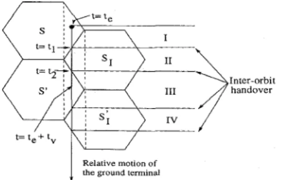
Figure 4: Successive Inter-orbit Handovers.
nodes s, and s, shown as
s,s3
where s, = f ( S , , t , ) ands j =
f
( S J , t e ) . Also, the cost function associated with the satellite and the ground routes are equal, i.e., C(S,Sj) =C(-) where C ( . ) is the cost function. Suppose the traffic load in location ( 5 , y) at time t , is L ( t e , (z, y)). An opti-
mal routing algorithm A can compute the optimal path P €or a source and destination pair, i.e., A(L(t,, (5, y))) = P . For time-homogeneous traffic load, the time reference can be ignored. Thus, the path P is optimal along time in the ground network. On the other hand, f (S,, t,) = si =
f
(S:,t,+
To). Thus, the optimum route in the ground network corresponds to the satellite route P at time t ,and to the satellite route P‘ at time t = t ,
+
TO where Pand
PI
correspond to the paths S I -+ 5’2-+
...
-+SK
andS; -+ S; --+
... -+
s;,
respectively.The proof of part C is trivial since the shortest path route is also minimum hop route if the traffic is time- and location-homogeneous, i.e., the cost of each ISL link is identical at any time. Thus, P’ is also a shortest path route all the time. 0
The goal of the footprint re-routing FR) is to find an finding algorithm after a handover. Theorem 1 guaran- tees the optimality a t all times if the original route is a minimum hop route. On the other hand, the optimality is guaranteed at certain time instants if the original route is obtained using location dependent traffic load. Moreover, the F R is applicable only to intra-orbit handovers since inter-orbit handovers require the use of neighbor succes- sor satellites. However, even in the case of an inter-orbit handover, FR is possible after the second inter-orbit han- dover. Figure 4 demonstrates this situation for a connec- tion established at t = t,. For simplicity, only one of the end-satellites (either source or destination) is shown. Also, for the sake of clarity, the footprints of the satellites are stationary, but the terminal moves with a speed relative to the satellites. The ground terminal is served by the origi- nal end-satellite
S
initially (regionI). At
t =
t~
>
te,
the first inter-orbit handover occurs. The ground terminal is served by SI (region 11) until t = t2>
tl when the second inter-orbit handover occurs. After t = t2, the ground ter- minal is served by S’ that is the successor of the original end satellite S . Thus, F R can be applied after the second handover. Note that the periodicity of the orbit ensures that t2<
t , + t v . Hence, parts A and C of Theorem 1 be- come applicable when the ground terminal enters the cell served by S’. Part B of the Theorem 1 is also applicable when t = t ,+
t o . This example demonstrates that for a connection experiencing multiple inter-orbit handovers, the F R can be applied after even-numbered handovers.A handover is necessary when one of the end satellites
-
goes out of the visibility region of the ground terminals involved in the communication. It is not possible t o use the F R a t this instant since FR replaces both end satellites with their respective successors. In other words, F R is only possible when the new end satellites are the successors of the end satellites in the original route. Thus, there is a need for a mechanism to handle the routing problem until the FR becomes applicable. The mechanism that we pro- pose for this task is called Footprint Handover Re-routing Protocol (FHRP), which consists of two phases. In the first phase which is called augmentation, a direct link is set up between the new end-satellite and the original route. If no such link exists, the connection is re-routed using the orig- inal routing algorithm. FR algorithm is applied after both of the end-nodes become the successors of the original end nodes. During a handover process, user terminals decide whether the augmentation or the F R should be used. The decision depends on the current time, the set-up time of the most recent optimum route, t,, the routing set Aopt of the optimum route and current routing set A. Thus, the mobile terminals keep this information during the lifetime of their connections. The storage overhead of FHRP is discussed in Section 3.3.
3.1
Augmentation Algorithm:
In this section, the augmentation algorithm for the source node of a connection is described. It is shown later that the same algorithm is also applicable t o the destination node. Assume that the most recent optimum route estab- lishment has been performed at t = t,. At t = t l
>
t,, the source terminal goes out of the coverage region of the source satellite, S,. Since the global coverage is guaran- teed, a new satellite S' covers the mobile terminal. S' is either the successor (intra-orbit handover) or the neighbor successor (inter-orbit handover) of S , as shown in Figure 5.If the necessary conditions as explained in the next section for F R are not held a t this moment, the source terminal initiates the augmentation algorithm by sending a service request message including the current routing set,
A,
t o5''.
The rest of the algorithm is handled by S' as follows: 1. The satelliteS"
checks whether this new connection can be supported by its up-/downlinks. The connec- tion would be blocked due t o insufficient capacity in the uplink channels. Moreover, the connection block- ing is also possible due t o insufficient capacity in theSatellite (cell) movement
Figure 5: Inter- and Intra-orbit Handovers. inal route. As an example, assume that a link be- tween S' and
Si
is found. Then, the new route isSf
+
Si
-+Si+l
-+
... -+ S K . The unused portion of the previous route,S1
-+ SZ--+
... +
Si-1,
is re- moved. The new routing set,A,
is sent t o the source terminal. The handover process is completed after the destination terminal is informed about the route changes.4. If a direct link between
5''
and the nodes in A with required capacity is not found, the original routing algorithm is performed. If a route with required ca- pacity is found, the resulting routing set, Aopt and route establishment time are sent t o the ground ter- minals.Note that the described augmentation algorithm can be applied for a handover involving the destination ground terminal with minor changes. To avoid simultaneous han- dovers of the source and the destination satellites of a con- nection, the destination terminal in FHRP sends a han- dover request message t o the source terminal. If the source terminal is in the process of a source handover, the desti- nation's request is held until the source handover is com- pleted. The source sends a handover permission message back t o the destination that follows a similar augmenta- tion process. Only difference is that, when a direct link is searched between S' and A in step 3, the satellite with the smallest index is checked first. Upon completion of the augmentation process, the new routing set is sent t o the ground terminals.
downlink if the destination terminal is covered by SI.
If there is no bandwidth available in the up and/or downlink(s), the connection is blocked and the source terminal releases the previous route.
If there is bandwidth available in up- and/or down- links, the new source satellite,
s',
first checks whether it is already serving the connection, i.e., it is checked whether S' is already in the routing set A. If the result is positive, say S' =Si
wherei
= 2, 3,...,
K ,the portion of the route up t o S' is deleted and the new route becomes
Si
+
Si+l
-+
...
+
S K . The new routing set,A,
is sent t o the ground terminals. If S' is not in A, a direct link t o one of the satel- lites in A is searched starting with the last member (satellite with the largest index) of A. This is be- cause a link t o a satellite with high index number results in a route with shortest length. If a direct link with sufficient capacity t o support the new con- nection is found, the link is augmented t o the orig-3.2
Footprint Re-routing Phase:
The disadvantage of the augmentation algorithm is that, when the route is augmented several times, the resulting route will not hold the optimality criterion of the original route. Thus, there is a need t o update the route at certain time intervals. The selection of the update interval is im- portant since the frequent re-routing attempts waste the network resources while a large re-routing interval results in the use of a non-optimal route for the connection most of the time. Here, we use Theorem 1 to solve the routing update interval problem. Theorem 1 states that the opti- mality of the original route is preserved in the Footprint Re-route a t certain times. Since the time when the Foot- print Re-route is optimum would only be known by the end terminals, F R should be initiated by one of the end terminals. Here, we assume that the FR is initiated by the source terminal. The route update time is based on the establishment time of the most recent optimum route
t,, optimum routing set dopt, and the current routing set A.
The first requirement for the FR is that the source and the destination satellites of the current route are the suc- cessors of the source and the destinatipn satellites of ,the original route, respectively, i.e., s d = S d O p t and S, = SSopt where Siopt and S:opt are the successors of the source and the destination satellites of the optimum route. The sec- ond requirement depends on the nature of the traffic load of the system and the optimum routing criterion based on Theorem 1 as follows:
1. If the traffic load is time- and location homogeneous or the original route is a minimum hop route, the FR
can be applied anytime when the successor end nodes are serving the connection, S d =
siopt
ands,
= S i o p t .2. If the traffic load is only time-homogeneous and the routing criterion depends on the traffic load (mini- mum cost routing), the FR is performed at t = t,+to.
Based on the above conditions, the source terminal ini- tiates the F R by sending a re-routing request t o the source satellite. The request includes the optimum route set dopt. The source satellite tries to establish a connection travers- ing the optimal route. If the connection re-routing is suc- cessful, i.e, no blocking occurs, the current route is re- moved. Upon the completion of the re-routing process, the user terminals update their routing information.
3.3
Storage Requirements
The storage requirement of the route information does not introduce major overhead for the ground terminals, since the longest possible loop-free route in a LEO network is bounded by N - 1 where N is the number of satellites in the network. This result is trivial since the longest loop-free route from the source to the destination passes through all the nodes in the network only once. The length of such a route is equal t o N - 1. For the shortest path routing algorithm, the bound for the length of the route is smaller as proven in the following theorem.
Theorem 2: Assume that P is a loop-free route in a LEO satellite network and Length(P) is the route length given in number of links. If the shortest path routing algorithm is used, then Length(P)
5
+
2, where 0 is the number of the orbits and L is the number of satellites per orbit.Proof: The proof is based on the connectivity structure of the network and the properties of the shortest path al- gorithm. Assume that the orbits are indexed as R; for
i = 1,
...,
0 where 0 is the number of orbits. The orbitsR,
andR,+l
are adjacent to each other. MoreoverR1
andRo
are also neighbors due t o the circular symmetry of the system. Thus, the maximum length of a route between two orbits is equal t oLgJ.
The satellites in each orbit are indexed similarly as S, for i = 1,...,
L , where L is the number of satellites per orbit. Each satellite has direct links with its up/down and leftlright neighbors. Thus, S, can communicate with S,+l with a direct link. Similar to the orbits, 5'1 and S, have a direct link between them due to the circular symmetry of the system. The maxi- mum length of a route between two satellites sharing the same orbit is equal to[$I.
The length of the shortest path between two satellites in different orbits is equal t o the sum of the maximum distance between the orbits and the maximum distance between the satellites sharing the same orbit, i.e., the length of the shortest path routes is bounded byLgJ +
L$J.
The constant term 2 in the The- orem is due t o the augmentation algorithm. As explained+
in Section 3.1, each application of the augmentation algo- rithm would extend the route at most 1 link. In the worst case, the augmentation algorithm is applied twice (one for each end terminal for inter-orbit handover). Thus, the length of the worst-case shortest path route is bounded by
1gj
+
L$J
+ 2 . 04
Conclusions
and
Future Work
A handover re-routing algorithm called Footprint Han- dover Re-routing Protocol (FHRP) has been proposed for the LEO satellite networks. The
FHRP
is a hybrid algo- rithm that consists of the augmentation and the footprint re-routing phases. In the augmentation phase, a direct link from the new end satellite to the existing route is found. In case, there is no such link with required capac- ity exists, a new route is found using the optimum route finding algorithm. In the footprint re-routing phase of the FHRP, the connection is routed through footprint re- route determined by the original optimum path. The goal of the re-routing is to establish an optimum route with- out applying the optimum route finding algorithm after a number of handovers. This property is significant be- cause, in the ideal case, the routin algorithm computes a the optimality of the original route is maintained during the communication.single route for each connection.
H
s proven in Section 3,Acknowledgements:
The authors would like to thank Ian F. Akyildiz at Georgia Institute of Technology and Jeff W. Evans at Georgia Tech Research Institute for valuable discussions.
References
[l] B.A. Akyol and D.C. Cox. Rerouting for Handoff in a Wireless ATM Networks. I E E E Personal Communications, [2] F. Dosiere, T. Zein, G. Maral, and J.P. Boutes. A Model for
the Handover Traffic in Low Earth-Orbiting (LEO) Satellite Networks for Personal Communications. Int. Journal of
Satellite Communications, 11:145-149, 1993.
[3] K.Y. Eng, M.J. Karol, M. Veeraraghavan, E. Ayanoglu, C.B. Woodworth, P. Pancha, and R.A. Valenzuela. A Wire- less Broadband Ad-Hoc ATM Local -Area Network. Wire- less Networks, 1(2):161-174, 1995.
[4] J.L. Grubb. IRIDIUM Overview. I E E E Communications Magazine, 29(11), 1991.
[5] E. Del Re, R. Fantacci, and G. Giambene. Handover Re- quests Queueing in Low Earth Orbit Mobile Satellite Sys- tems. In Proc. of the Second European Workshop on Mo- bile/Personal Satcoms, pages 213-232, 1996.
Architecture of the TELEDESIC Satellite
System. In Proc. of Int. Mobile Satellite Conference, pages
212-218, 1995. 3(5):26-33, Oct. 1996.
[6] M.A. Sturza.
[7] C. Toh. The Design and Implementation of a Hybrid Han- dover Protocol for Multimedia Wireless LANs. In Proc. of MOBICOM '95, 1995.
[8] M. Werner, C. Delucchi, H.-J. Vogel, G. Maral, and J.-J. De Ridder. ATM-Based Routing in LEO/MEO Satellite Net- works with Intersatellite Links. I E E E Journal o n Selected Areas zn Communications, 15(1):69-82, Jan, 1997. [9] R.A. Wiedeman and A.J. Viterbi. The Globalstar Mobile
Satellite System for Worldwide Personal Communications. In Proc. of Int. Mobile Satellite Conference, pages 46-49, 1993.