1
Elastic deformation of concrete. Determination of secant modulus of
elasticity in compression.
Pintea Augustin*1, Traian Oneţ2
1,2
Technical University of Cluj-Napoca, Faculty of Civil Engineering, 15 C Daicoviciu Str., 400020, Cluj-Napoca, Romania
Received 17 January 2012; Accepted 15 September 2012
Abstract
This paper describes the method for calculating the Secant Modulus of Elasticity for concrete used within road structures (across the fourth Pan-European corridor, Nadlac-Arad section), namely prestressed concrete bridge beams with pre and post tensioned reinforcements, with lengths between 25 and 41 meters. The determination of this modulus was carried out in order to reveal the values of the elastic deformation, which undoubtedly represents a key parameter in the case study of these elements.
Rezumat
Prezenta lucrare evidentiaza modul prin care s-a determinat Modulul de Elasticitate Secant al betonului ce a fost integrat in structuri rutiere(din coridorul 4 Paneuropean, tronsonul Nadlac-Arad), in speta pentru grinzi de pod din beton precomprimat cu armatura post si pre intinsa cu lungimi cuprinse intre 25 si 41 de metri.Determinarea acestui modul s-a efectuat in scopul calcularii deformatiilor elastice ale betonului inglobat in aceste elemente.
Keywords: Elastic deformation; Secant modulus of elasticity; Cylindrical specimens; Compressive strength, loading cycles
1. Introduction
The method used to calculate the Secant Modulus of Elasticity (or S.M.E.) is in full accordance with the
articles from the german standard DIN 1048-5:1991 [1] (which has concrete testing as the main interest), and is currently subjected to implementation and validation under EN 12390 European standard, and it will consequently have its romanian equivalent when this standard will become official.
*Corresponding author: Tel.: 0742118123
191
The reason for using the methods found in german standards instead of romanian ones, when
determining S.M.E. , has to do with the fact that Romania currently doesn’t have an European
harmonized standard to bring under regulation this type of determination.
2. Teoretical considerations
2.1. Elastic deformation
The deformation resulted from loading a concrete structure which recovers back to initial shape as soon as the applied load is removed, is called elastic deformation.This type of concrete deformation is largely influenced by the following parameters: graininess of the rock, water/cement ratio, concrete compressive strength, age of concrete and how the concrete test specimens are cured and stored.
For the calculus of elastic deformation the next formula is utilised. b el E
(1) where: - unit stress [N/mm2]Eb- elasticity modulus of concrete (E-module) [N/mm2]
Calculating on what scale the concrete deforms (the elastic deformation) is done with the help of Ecm
(the Secant Modulus of Elasticity), potentially taking into consideration tranquil flowing when
executed. And because the deformation characteristics of concrete is cuantified by S.M.E. (Ecm), the
use of this modulus is therefore justified [2].
The deviation from calculated real values for a specific concrete type can be quite considerable, and this is certainly the case with pretentious civil structures (like pretensioned slabs or bridges) in which the susceptibility to deformation is omnipresent.That’s why, it might be necessary to use real tested values instead of calculated ones when dimensioning the concrete elements.
2.2 Estimation of concrete deformation
Table 1 – Elasticity modulus for normal concrete according to DIN 1045-1:2008-08 [3]
Compressive
strength class
fck,cyl 1) fck,cube 2) Ec0m 3) 4) Ecm 5) 6)N/mm2 C 12/15
12 15 25800 21800 C 16/20
16 20 27400 23400 C 20/25 20 25 28800 24900 C 25/30 25 30 30500 26700 C 30/37 30 37 31900 28300 C 35/45 35 45 33300 29900 C 40/50 40 50 34500 31400 C 45/55 45 55 35700 32800
192 C 50/60 50 60 36800 34300 C 55/67 55 67 37800 35700 C 60/75 60 75 38800 37000 C 70/85 70 85 40600 39700 C 80/95 80 95 42300 42300 C 90/105 90 105 43800 43800
where: 1) fck,cyl - characteristic compressive strength of concrete, tested on cylinder specimen
after 28 days
2) fck,cube -characteristic compressive strength of concrete, tested on cube specimen
after 28 days
3) Ec0m - average elastic modulus of normal concrete as a tangent of tensioning–
dilation line (extension) in the point of origin 4) Ec0m - 3 / 1 , 8) ( 9500 fckcyl [N/mm2]
5) Ecm - average elastic modulus of normal concrete as a secant to 0,4 fcm
fcm fck,cyl 8
6) Ecm - =iEc0m with i (0,80,2fcm/88)1,0
The total deformation resulted from contraction, temperature variation, elastic deformation and tranquil flowing can be estimated with the following expression:
T E l l S T ) 1 ( (2) where:
l- length variation (shrinkage - / elongation +) [mm] l- the length of constructed elements [mm] - unit stress (compression - / strain +) [N/mm2] E- elasticity modulus [N/mm2] - final coefficient for tranquil flowing [-] S- final value for contraction (contraction - / dilatation +) [-]
T- thermal expansion coefficient [1/K]
T- difference in temperature (decrease - / increase +) [K]
Table 2 – Stress and deformation characteristics for normal concrete [3].
Row Col. 1 2 3 4 5 6 7 8 9 10 11 12 13 14 15 16
char.
measures Strength classes for concrete
analytical relation (explanation) 1 fck 12 a 16 20 25 30 35 40 45 50 55 60 70 80 90 100 [N/mm2] 2 fck,cube 15 20 25 30 37 45 50 55 60 67 75 85 95 105 115 [N/mm 2] 3 fcm 20 24 28 33 38 43 48 53 58 63 68 78 88 98 108 fcm= fck+8 [N/mm2]
193 4 fctm 1,6 1,9 2,2 2,6 2,9 3,2 3,5 3,8 4,1 4,2 4,4 4,6 4,8 5 5,2 fctm= 0,30 fck(2/3) ,to C50/C60 fctm= 2,12 ln(1+ fcm/10) ,from C55/67 5 fctk; 0,05 1,1 1,3 1,5 1,8 2 2,2 2,5 2,7 2,9 3 3,1 3,2 3,4 3,5 3,7 fctk; 0,05 = 0,7 fctm ,5 % quantile 6 fctk; 0,95 2 2,5 2,9 3,3 3,8 4,2 4,6 4,9 5,3 5,5 5,7 6 6,3 6,6 6,8 fctk; 0,95 = 1,3 fctm ,95% quantile 7a Ec0m 25800 27400 28800 30500 31900 33300 34500 35700 36800 37800 38800 40600 42300 43800 45200 Ec0m= 9500(fck+8)1/3 [N/mm2] 7b Ecm 21800 23400 24900 26700 28300 29900 31400 32800 34300 35700 37000 39700 42300 43800 45200 Ecm= αi·Ec0m with αi=(0,8+0,2fcm/88)≤1,0 [N/mm2] 8 εc1 -1,8 -1,9 -2,1 -2,2 -2,3 -2,4 -2,5 -2,55 -2,6 -2,65 -2,7 -2,8 -2,9 -2,95 -3,0 in ‰ 9 εc1u -3,5 -3,4 -3,3 -3,2 -3,1 -3,0 -3,0 in ‰ 10 n 2,0 2,0 1,9 1,8 1,7 1,6 1,55 in ‰ 11 εc2 -2,0 -2,03 -2,06 -2,1 -2,14 -2,17 -2,2 in ‰ 12 εc2u -3,5 -3,1 -2,7 -2,5 -2,4 -2,3 -2,2 in ‰ 13 εc3 -1,35 -1,35 -1,4 -1,5 -1,6 -1,65 -1,7 in ‰ 14 εc2u -3,5 -3,1 -2,7 -2,5 -2,4 -2,3 -2,2 in ‰ C12/15 strength class can only be used for predominantly static actions(non operative state)
3.Testing methodology
3.1 Scope
This paper specifies the procedure for determining the secant modulus of elasticity in compression for hardened concrete, on test specimens which may be cast or taken from a structure.
3.2 Terms
For the purposes of this paperwork, the following terms apply:
3.2.1Initial Secant Modulus of Elasticity - EC,0
Secant slope of the stress strain curve at first loading
3.2.2 Stabilized Secant Modulus of Elasticity - EC,S
Secant slope of the stress strain curve after 3 loading cycles
3.2.3 Measuring line
A straight line laying on the lateral surface of tested specimen and parallel to the vertical axis. See below.
194
Figure 1 – Measuring line on cylindrical specimens, having a diameter of 150 mm and height of 300 mm 3.2.4 Base or gauge length
Length used as reference base for strain measurement
3.3 Principles
The work presented in this document intends to offer a procedure for determining S.M.E under
compression of hardened concrete cylindrical specimens.
This test method allows the determination of two Secant Modules of Elasticity: the initial modulus, EC,0 measured at first loading and the stabilized modulus, EC,S measured after three loading cycles.
Tested specimens were loaded under axial compression, the stresses and strains were recorded and the slope of the secant to the stress-strain curve was determined at first loading and after three loading
cycles, never forgetting that the secant slope is essentially known as the Secant Modulus of Elasticity in
compression.
3.4 Apparatus
3.4.1 Testing machine
A compression testing machine that conformed to EN 12390-4 standard [4], with following additional requirements:
a)- suitable for execution of programmable loading cycles;
b)- able to increase and decrease the load at a constant rate within a given tolerance (see 3.6.3.b); c)- able to maintain a constant load at selectable nominal values with a maximum variation within
±5%;
d)- calibrated as Class 1 to EN 12390-4 [4] over the working range from the lower stress to the upper
195
Figure 2 - Compression testing machines used for determination of S.M.E.
3.4.2 Instrumentation
Instrumentation measuring the strain of the specimen under axial compression along a measuring axis
had an accuracy better than ± 10m/m, in the range from 0 to 1000m/m.
Figure 3 - Strain measuring instruments
With the help from this instrumentation we measured the strain by recording length change, and afterwards calculated the final value of strain with the following formula:
0 L L
(3) in which: L- length variationL0- initial gauge length of the instrument 3.4.3 Base or gauge length
196
The base or gauge length of the strain measuring instrument was between two-thirds of the
specimen diameter (or section width) and one-half of the specimen length and not less than 3Dmax ,
where Dmax is the maximum nominal aggregate size.
3.5 Test specimens
3.5.1Shape, dimensions and number of specimens
The test specimens were moulded cylinder shaped concrete elements, complying with the requirements
of EN 12390-1 [5].The dimension d(diameter or width) had to be at least 3.5 times the maximum
aggregate size, whilst the ratio between specimen length L and the dimension d placed in the range 2
L/d 4.
Reference test specimens were concrete cylinders 150 mm in diameter with a height of 300 mm, and all
the adjustments of test specimens complied with EN 12390-3 [6]. Two companion specimens were available for the determination of compressive strength as described in 3.6.2.
3.5.2Curing, storage and conditioning
Moulded specimens were cured and stored in accordance with EN 12390-2 [7]. Before testing they
were maintained at 20 ± 2°C temperature for sufficient time for strain measuring instruments to be
securely fixed, but no longer than 24 hours out of water.
3.6 Procedure
3.6.1 Specimen instrumentation and positioning
The strain measuring instruments were positioned in such a way that the measuring base was at equivalent distance from the end faces of the specimen. These strain measuring instruments (three in number) were symmetrically arranged with respect to the central axis of the specimen.
Before the applied loading, the strain measuring system was checked to confirm that it was functioning correctly and accurately, while the tested specimen was being centered on the lower
197
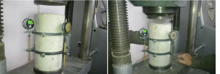
Figure 4 - Specimen instrumentation and positioning
3.6.2Determination of compressive strength
The compressive strength of concrete fcm was determined (in accordance with EN 12390-3) [6] on
companion specimen(s) having the same size and shape of those specimens used for secant modulus of elasticity determination.
The mean value of compressive strength fcm is used to define the stress levels of the test
cycle that occur in the process of determining the Secant Modulus of Elasticity. If companion test
specimens for the determination of compressive strength are not available the compressive strength may be estimated from non destructive tests.
198
Figure 5 - Determination of compressive strength
3.6.3Determination of secant modulus of elasticity
3.6.3.a Preloading cycles
Three preloading cycles were carried out in order to check the instrumentation and wiring stability (first check) and the specimen positioning (second check). For each one of the three preloading cycles,
the stress applied to the specimen was progressively increased at a rate of 0,6 ± 0,2 MPa/s up to the
lower stress σb = fcm/9. The lower stress was then maintained at ±5% of the nominal value for 20 ± 2 s.
Next step, the applied stress was reduced at a rate of 0,6 ± 0,2 MPa/s down to the preload stress σp ,
which is an arbitrary value that shall always remain in the range from 0,5 MPa to 1,0 MPa. Following
step, the preload stress was maintained for 20 ± 2 s.
During the final 10 s of the preload stress phase of the first cycle,the strain measuring instruments were
reseted to zero. Through the final 10 s of the lower stress phases of the second and third cycles, the
strain εb(along each measuring line) was recorded.
After the 3 cycles, the preload stress σp was kept active within ±5% of the nominal value and the
following consecutive checks were performed within 60 s time frame.
First check
On each measuring line the strain εb must be different from zero and the variation from the second to
the third cycle must be lower than 20 μm/m.
Second check
The strains εb at the third cycle on all the measuring lines must not differ from their average by more
199
Figure 6- Preloading cycles
3.6.3.b Elastic modulus cycle
The applied stress was progressively increased at a rate of 0,6 ± 0,2 MPa/s from the preload stress to
the lower stress (σb = fcm/9). The lower stress was maintained within ±5% of the nominal value for 20
± 2 s, whilst in the final 10 s, the strain εb,0 was read and recorded along each measuring line. A number of three loading cycles were carried out.
For each one of the three cycles, the stress applied to the specimen was increased at a rate of 0,6 ± 0,2
MPa/s until the upper stressσa = fcm/3 was reached. The upper stress was then maintained within ±5%
of the nominal value for 20 ± 2 s.
The applied stress was then reduced at a rate of 0,6 ± 0,2 MPa/s to the lower stressσb = fcm/9. After
that, the lower stress was maintained within ±5% of the nominal value for 20 ± 2 s.
During the final 10 s of the upper stress phase of the first and third cycles, the corresponding strains
εa,1 and εa,3 values were recorded(along each measuring line).
Through the final 10 s of the lower stress phase of the second cycle, the strain εb,2 value was
recorded (along each measuring line).
After three completed cycles, the applied stress was increased at the rate given in EN 12390-3 [6] until failure occurred, and the value of compressive strength was recorded.
200
Figure 7 – Final stage of determining S.M.E.
The test cycle for the determination of elastic modulus is given in figure below.
Figure 8 - Test cycle
3.7 Calculation of secant modulus of elasticity
3.7.1 Initial secant modulus of elasticity
The initial secant modulus of elasticityEC,0 is defines as: 0 , 1 , 0 0 , b a r b r a C E (4)
where: is the difference between the applied stress
0 is the corresponding strain difference measured at the first loading
201
br is the real stress corresponding to the nominal value σb
a,1 is the average strain at σa at first cycle
b,0 is the average strain at σb before the first cycle
3.7.2 Stabilized secant modulus of elasticity
The stabilized secant modulus of elasticityEC,S is defines as:
2 , 3 , , b a r b r a S S C E (5)
where: is the difference between the applied stress
S is the corresponding strain difference measured after three cycles
cm/3
r a f
is the real stress corresponding to the nominal value σa
br fcm/9 is the real stress corresponding to the nominal value σb
a,3 is the average strain at σa at third cycle
b,2 is the average strain at σb after second cycle
Note: the degree of variation of S.M.E. from EC,0 to EC,S may be an indication that the material from
which the testing specimens are made, is susceptible to stress induced micro-cracking.
4. Results
Sample number Concrete strength class Section area [mm2] Cast date Try date Average compressive strength fcm [N/mm2] Compressive strength after f2 try [N/mm2] Characteristic compressive strength value fck [N/mm2] Elasticity modulus, tangent to point of origin, Ec0m [N/mm2] Secant modulus of elasticity Ecm [N/mm2] first cylinder C40/50 17662,5 21.03.12 30.03.12 52,00 43,60 44,00 35 459 32 558 second cylinder C40/50 17662,5 21.03.12 18.04.12 56,62 50,47 48,62 36 479 33 8785.Conclusions
After careful data analysis, the following conclusions were drawn:
For concrete strength class C40/50, the value of Secant Modulus of Elasticity for the second specimen
tested (age 28 days) was very close to correspondent value from Table 2, a table value which was taken
from DIN, 1045-1:2008-08 standard [3]. Our data for this parameter was 33878 N/mm2, as compared
202
As for the other tested specimen (age 10 days), the value of Secant Modulus of Elasticity was just under
the value of tested cylinder (age 28 days), 32878 N/mm2 compared to 33878 N/mm2.Again, very
conclusive and relevant data obtained from our tests.
At present day in Romania, the experimental determination of the static modulus of elasticity under compression for concrete is done according to the articles found in STAS 5585-71.
The above mentioned standard defines the static modulus of elasticity under compression for concrete, as the ratio between the increase of the unit stress and the corresponding increase of specific
deformation recorded in the 0,05…0,30 Rpr interval (where Rpr is the concrete prismatic resistance).[8]
Within this standard, the static modulus of elasticity under compression for concrete is shortly abbreviated to elasticity modulus; and as for the determination of this modulus, prismatic shaped concrete specimens will be used exclusively. The manufacturing and curing for these concrete specimens and the characteristics of the compression testing machines are described in STAS 1275-70 (a standard that currently is nullified).
Under the current circumstances, with a 41 year old standard that has the calculus method for reinforced concrete based on admissible resistances instead of the limit state method , it is very clear that this romanian standard is completely out of date.
That’s why almost any article from the STAS 5585-71(which is still a valid standard in Romania at
present date, 15.11.2012) fails to be in accordance with the articles exposed in the Eurocode 2 – Design
of concrete structures , a code made mandatory in Romania, starting March the 1st, 2010. From symbols and characteristics to physical measures and measure units, all is outdated.
The entitled Romanian institutions, such as the Romanian Standardization Association, failed to dissolve this standard once the European Standard EN 1992-1-1:2004 was made active in december 2004, a date at which it formerly became the official romanian standard, inherting all articles from the equivalent European standard SR. EN 1992-1-1:2004. Even more, after september 2002, these institutions had the obligation to nullify the STAS 5585-71 standard, as the European series of
Standards EN 12390 – Testing hardened concrete were being adopted and harmonized as the romanian
equivalent standards. But that also didn’t happen, so we were left in the situation we are in right now. Considering the arguments from above and the fact that there still isnt’t a standard on the romanian market that can describe a complete and valid methodology for calculating the secant modulus of elasticity under compression for a concrete specimen, the german method for determining the static modulus of elasticity was consulted and evaluated. This method is in direct accordance with the articles found in DIN 1048-5:1991 standard .[1]
Within this standard it is stated that cylindrical concrete specimens (150 mm in diameter and 300 mm
in length) should be used when determining the static modulus of elasticity. The mathematical expression for this modulus is presented below.
u u b E 0 0 (6)
203
Using cylindrical concrete specimens instead of the prismatic ones when determining the static and secant modulus of elasticity, not only improves accuracy of the results obtained, but also eliminates the problem risen by the concentration of forces around edges; a phenomenon that only appears when using prismatic concrete specimens. This is why, the german standard DIN 1048-5:1991 expressly indicates that cylindrical concrete specimens should be used when making these type of determinations. At European Community level, an ongoing process that targets the elaboration of a method to determine the secant modulus of elasticity under compression for normal concrete is currently
underway. When it will be finalized, it will be added to the EN 12390 – Testing hardened concrete
series of standards.
This method (which is still under development) it’s based on extended inquiry and comparison of active national standards for testing hardened concrete, followed by the analysis of a testing program in which several laboratories are currently involved.
Determining the secant modulus of elasticity under compression for normal concrete with the experimental method presented in this paper, was done for the first time in our country by the author of this article, and made possible thanks to careful studying and documenting of specific national, european and various other affiliated standards and documentation. Contributing to this successful undertaking, was S.C. LUPP Gmbh, Romania-Sibiu division, which welcomely shared its testing laboratory facilities and needed material resources. So, for this reason I would like to thank the company administration for their support and effort.
To see that the experimental data obtained here, has already been used in the manufacturing process of single casted prestressed concrete beams with pretensioned reinforcement (36 meters in length), which were needed for various bridges along the Nadlac-Arad and Orastie-Sibiu highways, is nevertheless a great satisfaction.
6.References
[1] DIN 1048-5:1991. Testing methods for concrete;hardened concrete, specially prepared
specimens
[2] Traian Onet, Radu Ioan Olar. Beton precomprimat, editura U.T. Press. Cluj-Napoca, 2007
[3] DIN 1045-1:2008-08. Concrete, reinforced and prestressed concrete structures
[4] EN 12390-4:2010. Testing hardened concrete – Part 4: Compressive strength –
Specification for testing machines
[5] EN 12390-1:2009. Testing hardened concrete – Part 1: Shape, dimensions and other
requirements of specimens and moulds
[6] EN 12390-3:2009. Testing hardened concrete – Part 3: Compressive strength of test
specimens
[7] EN 12390-2:2009. Testing hardened concrete – Part 2: Making and curing specimens for
204
[8] STAS 5585 – 71 . Determination of the modulus of compressibility of concrete
[9] Lusa Tuleasca, Aurel Cuciureanu, Petru Mihai. Beton,Beton armat,Beton precomprimat,
![Table 2 – Stress and deformation characteristics for normal concrete [3].](https://thumb-us.123doks.com/thumbv2/123dok_us/1780022.2753591/3.918.111.805.87.217/table-stress-deformation-characteristics-normal-concrete.webp)