Software of the Earth Simulator
Atsuya Uno
The Earth Simulator Center, Japan Agency for Marine-Earth Science and Technology, 3173–25 Showa-machi, Kanazawa-ku, Yokohama, 236-0001 JAPAN
Email: [email protected]
(Received February 2, 2005; Revised manuscript accepted June 16, 2005)
Abstract The Earth Simulator (ES) is a distributed-memory parallel system with a peak performance of 40
TFLOPS. The system consists of 640 nodes connected via a fast 640 ×640 single-stage crossbar network. In this paper, an overview of software of the Earth Simulator (the operating system, Operation Management Software and a programming environment) is presented. The operating system of ES (ES OS) is based on SUPER-UX, which is the operating system for NEC’s commercial Supercomputer SX series, and ES OS is enhanced to meet a scalability of the ES system, and Operation Management Software is developed to man-age this large system efficiently. They provide Single System Imman-age (SSI) system operation, system manman-age- manage-ment and batch job control for the ES system. As a programming environmanage-ment, ES provides a three-level hier-archy of parallel processing. Useful languages and libraries are prepared for users to develop well-parallelized programs and to achieve the highest performance. FORTRAN90/ES and C++/ES have advanced capabilities of automatic vectorization and microtasking, and HPF/ES enables users to develop parallel programs easily. MPI/ES provides high-speed communication optimized for the ES architecture.
Keywords: ES (Earth Simulator), OS (Operating System), Scheduler, HPC (High Performance Computing),
HPF (High Performance Fortran), MPI (Message Passing Interface)
1. Introduction
The Earth Simulator (ES) was developed to promote research and development for a clear understanding and more precise prediction of global changes of the earth system.
ES is a MIMD-type, distributed-memory and parallel system, and consists of 640 processor nodes connected
via a fast 640 × 640 single-stage crossbar network. The
theoretical peak performance is 40 TFLOPS. In order to operate this large system efficiently, the operating system of ES (ES OS) and Operation Management Software were developed. ES OS is enhanced especially to meet the scalability of the ES system, and Operation Management Software manages the ES system efficient-ly. They provide Single System Image (SSI) system oper-ation, system management and batch job control for the ES system. The major components of Operation Management Software are Network Queuing System II, the customized scheduler and System Manager.
As a programming environment, ES provides three-level parallelism, and users can develop the well-paral-lelized programs using useful languages and libraries. FORTRAN90/ES and C++/ES have advanced capabilities of automatic vectorization and microtasking, and HPF/ES provides easy parallel program development environment.
MPI/ES is designed and optimized to achieve highest per-formance of communication on the ES architecture.
In this paper, an overview of these software of the Earth Simulator is introduced.
2. Overview of the Earth Simulator System
ES is a MIMD-type, distributed-memory, parallel sys-tem, in which 640 processor nodes are connected via a
fast 640 × 640 single-stage full crossbar network
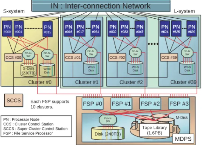
(IN:Inter-connection Network)[1] (Fig. 1). The
inter-Fig. 1 The configuration of the Earth Simulator.
CCS #00 CCS #01 CCS #02 CCS #39 Work Disk SW Work Disk FC-AL SW FC-AL SW FC-AL SW FC-AL SW FSP #0 FSP #1 FSP #2 FSP #3 S-system L-system MDPS PN #000 PN #001 PN #015 PN #016 PN #017 PN #031 PN #016 PN #017 PN #031 PN #032 PN #033 PN #047 PN #032 PN #033 PN #047 PN #624 PN #625 PN #639 PN #624 PN #625 PN #639 IN : Inter-connection Network Cluster #39 Work Disk Cluster #2 FC-AL Cluster #1 S-Disk (230TB) Work Disk Cluster #0 SCCS Each FSP supports 10 clusters. PN : Processor Node CCS : Cluster Control Station SCCS : Super Cluster Control Station FSP : File Service Processor
M-Disk Tape Library (1.6PB) Disk (240TB) Fabric SW
connection bandwidth between every two PNs is 12.3 GB/s in each direction. Thus the total bandwidth of IN is 7.87 TB/s. Each processor node has 8 vector-type arith-metic processors (APs) that are tightly connected by a 16 GB shared memory. The peak performance of each AP is 8 GFLOPS. Therefore, the total number of APs, the total main memory and the theoretical peak performance of ES are 5,120, 10 TB and 40 TFLOPS, respectively.
ES has two-type user disk areas. One is termed “S-Disk” and the other is termed “M-Disk.” S-Disk is a mag-netic disk system and its capacity is 230 TB. M-Disk is a hierarchical storage management system and consists of a 240 TB magnetic disk system and a 1.6 PB cartridge tape library (CTL). M-Disk is managed by 4 File Service Processors (FSPs), and an FSP executes the file staging between the work disk of a PN and the user disk. Therefore each FSP services 160 nodes.
To operate this large system efficiently, 640 processor nodes are divided into 40 groups termed “cluster.” ES is basically a batch-job system and most of the clusters are used for batch jobs. However there is a very special clus-ter clus-termed “S-system.” In S-system, two nodes are assigned for interactive nodes, and the remaining nodes are assigned for small-scale (single node) batch jobs. All clusters except S-system are used for large-scale batch jobs and are termed “L-system.” Each cluster has a work-station termed “Cluster Control Station (CCS).” A CCS links all nodes within a cluster, and controls startup and shared resources among nodes. All CCSs are controlled by a supervisor workstation called “Super Cluster Control Station (SCCS).”
3. Operating System
The Earth Simulator Operating System (ES OS) pro-vides high-speed parallel processing environment not only for specific applications but also for general applica-tions from small-scale programs to large-scale programs. And ES OS can provide Single System Image (SSI) sys-tem operation.
ES OS is an enhanced version of NEC’s Super-UX Operating System[2]. The Super-UX is the operating sys-tem for NEC’s commercial Supercomputer SX series. The Super-UX is based on UNIX System V with BSD features and has been enhanced to meet various kinds of supercomputing requirements as follows;
•Vector processing
•Parallel processing for shared memory
•Parallel processing for distributed memory
•Batch system
•High-performance I/O
•Cluster management
The Super-UX has a good scalability from a single
node to many nodes, but ES has 640 nodes connected via IN and has 5,120 APs. Therefore ES OS has been enhanced to meet a scalability of the ES system, and many useful functions for large multi-node system are implemented in ES OS. For instance, the operation man-agement function is implemented as easy manman-agement of the whole system under the Super Cluster System.
In the Super Cluster System, the system is divided into appropriate units and these units are controlled by a sin-gle machine. In ES, 640 nodes are divided into 40 clus-ters and all clusclus-ters are controlled by Super Cluster Control Station (SCCS). This cluster system provides easy management of the ES system and realizes high reli-ability and availreli-ability.
4. Operation Management Software
As described above, ES is basically a batch-job system. Network Queuing System II (NQSII) is introduced to manage the batch jobs, and we have developed the cus-tomized scheduler for ES. We have also developed the additional operation-support system to monitor the state of PNs, to manage the user’s information and other func-tions (Fig. 2). This system consists of System Manager, Automatic Operation System, User Information Manager, Accounting System and Broadcasting System.
4.1 Network Queuing System II
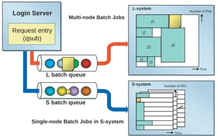
The Network Queuing System II (NQSII) is a batch processing system for a high-performance cluster system. In ES, there are two-type batch queues. One is S batch queue and the other is L batch queue (Fig. 3). S batch queue is aimed at being used for a pre-run or a post-run for large-scale batch jobs (making initial data, processing
Fig. 2 Operation Management Software. This system consists
of Network Queuing System II, System Manager, Automatic Operation System, User Information Manager, Accounting System and Broadcasting System. SM communicates with NQSII tightly, and controls other components. Data Base
NQSII
SM (System Manager) Automatic Operation System (AOS) Accounting System (ACCT) User Information Manager (UIM) Broadcasting System (BCS)results of a simulation and other processes), and L batch queue is for a production run.
S batch queue is designed for single-node batch jobs. In S batch queue, ERSII[4] is used as a scheduler and does a job scheduling based on CPU time. Programs are confined in one of PNs in S-system, and APs and memo-ry are shared with other programs in the same PN. PNs in S-system manage S-Disk, thus programs can access user’s files in S-Disk directly.
On the other hand, L batch queue is designed for multi-node batch jobs. In this queue, the customized scheduler for ES is used as the scheduler. We have been developing this scheduler with following strategies[3];
•The nodes allocated to a batch job are used
exclu-sively for that batch job.
•The batch job is scheduled based on elapsed time
instead of CPU time.
These strategies enable to estimate the job termination time and make it easy to allocate nodes for the next batch jobs in advance. This means that the scheduler can allo-cate nodes to even a large-scale batch job when that batch job is submitted. Therefore large-scale batch jobs could be executed in a short waiting time although ES has basi-cally adopted a single batch queue environment in L-sys-tem.
PNs of L-system are prohibited from access to the user disk to ensure enough disk I/O performance. Therefore, user’s files used by the batch job are copied from the user disk to the work disk before the job execution. This process is called “stage-in.” In the job scheduling, it is important to hide this staging time. To hide the staging time, staging process of the next scheduled batch job is executed by FSPs in the background of the job execution in PNs (Fig. 4). This process is executed without using APs of PNs, and produces a little effect on the disk I/O
performance. After the job execution, results of the simu-lation are also copied from the work disk to the user disk. This process is called “stage-out.”
Main steps of the job scheduling are summarized as follows (Fig. 5);
(1) Node Allocation
(2) Stage-in (copies files from the user disk to the work disk automatically)
(3) Job Escalation (reschedules for the earlier estimated start time if possible)
(4) Job Execution
(5) Stage-out (copies files from the work disk to the user disk automatically)
J1 j2 J2 j1 j3 J3 L-system Time Number of APs Time Login Server
Single-node Batch Jobs in S-system
S batch queue L batch queue
Request entry (qsub)
Multi-node Batch Jobs
S-system
Number of PNs
Fig. 3 Queue configuration of the Earth Simulator. ES has
two-type queues. S batch queue is designed for single-node batch jobs and L batch queue is for multi-node batch jobs. Work User Stage-in Access B A FSP Processor Node Batch Job B (next) Batch Job A (running) Disk Disk Stage-out
Fig. 4 File Staging Process. File B used by the next scheduled
batch job B is copied from the user disk to the work disk (stage-in), and File A created by the running batch job A is copied from the work disk to the user disk after the job execution (stage-out). These processes are executed by FSPs in the background of the job execution in PNs without using APs of PNs. They affect mainly disk I/O performance, but produce a little effect.
Submitted Terminated Node Allocation Stage-in Stage-out Waiting Execution Escalation
(1) Node Allocation
When a new batch job is submitted, the scheduler searches available nodes which has sufficient vacant work disk space and execution time. If the scheduler finds enough available nodes, it allocates those nodes and the estimated start time to the batch job, and starts stage-in process.
(2) Stage-in
After the nodes are allocated to the batch job, stage-in process starts. This process is executed by FSPs without using APs of PNs. By analyzing the file path, NQSII chooses an FSP that does file copy. And an FSP copies user’s files from the user disk to the work disk while a PN executing another batch job.
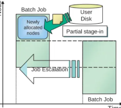
(3) Job Escalation
The scheduler checks the estimated start time of each batch job periodically. If the scheduler finds the earlier start time than the estimated start time, it allocates the new start time to the batch job. This process is called “Job Escalation” (Fig. 6). At this time, if some nodes are able to be allocated to the same batch job again, the scheduler doesn’t execute stage-in process toward those nodes, and starts stage-in process only toward newly allo-cated nodes. This process is called “partial stage-in.”
(4) Job Execution
When the estimated start time has arrived, the sched-uler executes the batch job. If stage-in process hasn’t been finished until the estimated start time, the scheduler cancels this estimated start time, and does rescheduling after stage-in process is completed.
When the job execution is finished or the declared elapsed time is over, the scheduler terminates the batch job and starts stage-out process.
Time Node User Disk Partial stage-in Batch Job Newly allocated Job Escalation Batch Job New start time Estimated start time
nodes
Fig. 6 Job Escalation. If the scheduler finds the earlier start time than the estimated start time, the new start time is allocated to the batch job. And the scheduler starts stage-in process only toward newly allocated nodes. This process is called “partial stage-in.”
(5) Stage-out
After the job execution, the scheduler starts stage-out process. This process is also executed by FSPs without using APs of PNs. The priority of stage-out process is lower than one of stage-in process, because stage-in process is need to be finished as fast as possible to ensure the estimated start time of the batch job.
L-system is basically operated as a single batch queue environment, but L-system can be operated as some batch queues environment at the same time. This process can be done without stopping the ES system. NQSII can manage each batch queue as an independent queue, and can increase or decrease nodes of any queue anytime.
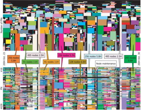
Fig. 7 shows the number and size of batch jobs execut-ed in ES in 1 week. The top figure shows the size and the elapsed time of the batch jobs, and the bottom figure indi-cates the job execution situation of each PN. The rectan-gles painted different colors are ones for different batch jobs. Since all nodes of ES have the same performance, ES can execute a batch job on any nodes in the same per-formance. So the nodes allocated to one batch job could be scattered. In the bottom figure, the boxes of the same color on the same vertical axis correspond to the same batch job, and those boxes are arranged to shape one rec-tangle that indicates one batch job in the top figure. The width of a rectangle depicts the elapsed time from the start time to the termination time. The height denotes a number of nodes. The black area in the bottom figure shows the nodes either waiting for execution or for main-tenance. We maintain each 1 cluster (16 nodes) per week. As can be seen in Fig. 7, ES can execute batch jobs of many sizes simultaneously and has kept a high ratio of the node utilization using this scheduling algorithm.
4.2 System Manager
System Manager (SM) manages the communication between NQSII and other components (Automatic Operation System, Accounting System and other compo-nents). SM communicates with NQSII tightly, and moni-tors the state of all batch jobs in batch queues. The main function of SM is the distribution of the events from NQSII to other components and the control of other com-ponents.
4.3 Automatic Operation System
Automatic Operation System (AOS) controls power management of each PN. AOS controls to start up and stop a PN according to the operation schedule of ES. And AOS monitors the load of the ES system and stops or starts up a PN to avoid the waste of energy corresponding to the system load.
4.4 User Information Manager
User Information Manager (UIM) manages the user’s information and the resource assigned to the user. When the batch job is submitted, NQSII connects to UIM and checks the resource which the batch job requires. If its required resource is over the remaining resource, NQSII deletes that batch job.
4.5 Accounting System
Accounting System (ACCT) collects the information of the batch job (process account, performance informa-tion and other informainforma-tion) after the job execuinforma-tion. And ACCT registers these information in the Data Base System.
4.6 Broadcasting System
Broadcasting System (BCS) provides the information of ES and user’s batch job via World Wide Web. Therefore, users can see the state of ES, the batch jobs and the used resource using a conventional web browser.
5. Programming Environment
ES provides a three-level hierarchy of parallel process-ing; vector processing in an AP, parallel processing with shared memory in a PN, and parallel processing among PNs via IN. To achieve the highest performance of ES fully, users must develop well-parallelized programs that make the most use of such parallelism.
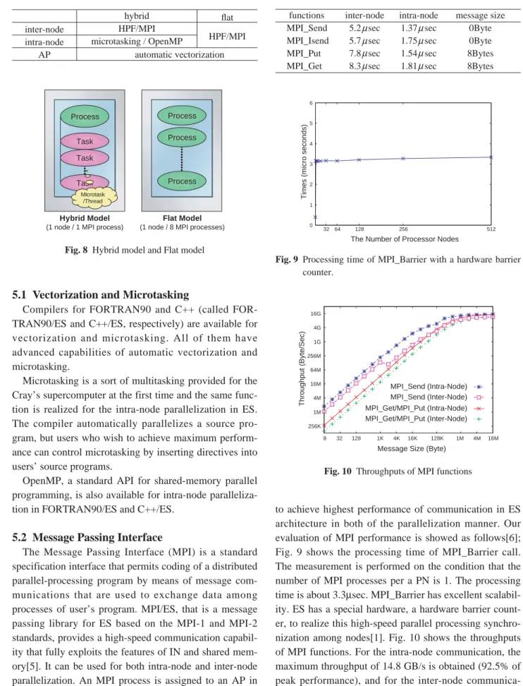
There are two different usages of the three-level paral-lelism (Table 1, Fig. 8). The first is on the hybrid model, where users must distinguish the intra-node and inter-node parallelism and specify each of the two explicitly in a program. The inter-node parallelism can be specified with HPF or MPI, and the intra-node is specified with microtasking or OpenMP in this model of parallelization. The second is on the flat model, where ES as a whole
is viewed as a flat system composed of 5,120 (= 640×8)
APs and users do not have to distinguish the intra-node and inter-node parallelism. Parallelization can be done with HPF or MPI in this model of parallelization.
Fig. 7 The number and size of batch jobs executed in ES from 23 to 30 October 2004 (1 week.) The top figure
shows the size and the elapsed time of the batch jobs, and the bottom figure indicates the job execution situation of each PN. The rectangles colored differently correspond to different batch jobs and the same colored rectangles on the same vertical axis mean one batch job. The horizontal axis is time. The verti-cal axis of the bottom figure indicates a PN number, and the top is node #016 and the bottom is node #639 (nodes from #000 to #015 are not shown because they belong to S-system.) In the top figure, the rectangles in the bottom figure are arranged to shape one rectangle that indicates one batch job. The height of the rectangle denotes the number of nodes and the width means the used elapsed time.
5.1 Vectorization and Microtasking
Compilers for FORTRAN90 and C++ (called FOR-TRAN90/ES and C++/ES, respectively) are available for vectorization and microtasking. All of them have advanced capabilities of automatic vectorization and microtasking.
Microtasking is a sort of multitasking provided for the Cray’s supercomputer at the first time and the same func-tion is realized for the intra-node parallelizafunc-tion in ES. The compiler automatically parallelizes a source pro-gram, but users who wish to achieve maximum perform-ance can control microtasking by inserting directives into users’ source programs.
OpenMP, a standard API for shared-memory parallel programming, is also available for intra-node paralleliza-tion in FORTRAN90/ES and C++/ES.
5.2 Message Passing Interface
The Message Passing Interface (MPI) is a standard specification interface that permits coding of a distributed parallel-processing program by means of message com-munications that are used to exchange data among processes of user’s program. MPI/ES, that is a message passing library for ES based on the MPI-1 and MPI-2 standards, provides a high-speed communication capabil-ity that fully exploits the features of IN and shared mem-ory[5]. It can be used for both intra-node and inter-node parallelization. An MPI process is assigned to an AP in “flat” parallelization, or to a PN containing microtasks or OpenMP threads in “hybrid” parallelization.
MPI/ES libraries are designed and optimized carefully
to achieve highest performance of communication in ES architecture in both of the parallelization manner. Our evaluation of MPI performance is showed as follows[6]; Fig. 9 shows the processing time of MPI_Barrier call. The measurement is performed on the condition that the number of MPI processes per a PN is 1. The processing time is about 3.3µsec. MPI_Barrier has excellent scalabil-ity. ES has a special hardware, a hardware barrier count-er, to realize this high-speed parallel processing synchro-nization among nodes[1]. Fig. 10 shows the throughputs of MPI functions. For the intra-node communication, the maximum throughput of 14.8 GB/s is obtained (92.5% of peak performance), and for the inter-node communica-tion, the maximum throughput of 11.6 GB/s is obtained (94.3% of peak performance). Table 2 shows the start-up costs of MPI-functions. The results show the start-up
Table 1 Programming models of ES
inter-node intra-node AP hybrid HPF/MPI microtasking / OpenMP flat HPF/MPI automatic vectorization Task Process Process Process Process Hybrid Model (1 node / 1 MPI process)
Flat Model (1 node / 8 MPI processes)
Task Task
Microtask /Thread
Fig. 8 Hybrid model and Flat model
Table 2 Start-up costs of MPI functions.
functions MPI_Send MPI_Isend MPI_Put MPI_Get inter-node 5.2 sec 5.7 sec 7.8 sec 8.3 sec intra-node 1.37 sec 1.75 sec 1.54 sec 1.81 sec message size 0Byte 0Byte 8Bytes 8Bytes 0 1 2 3 4 5 6 32 64 128 256 512
The Number of Processor Nodes
Times (micro seconds)
Fig. 9 Processing time of MPI_Barrier with a hardware barrier
counter. 256K 1M 4M 16M 64M 256M 1G 4G 16G 8 32 128 1K 4K 16K 128K 1M 4M 16M MPI_Get/MPI_Put (Intra-Node) MPI_Get/MPI_Put (Inter-Node) MPI_Send (Intra-Node) MPI_Send (Inter-Node) Throughput (Byte/Sec)
Message Size (Byte)
costs are shorter than 10 µseconds. As can be seen from these results, MPI/ES has a good performance of commu-nication.
5.3 High Performance Fortran
High Performance Fortran (HPF) is designed to sup-port efficient and sup-portable parallel programming for scal-able systems[7]. Compared to MPI, an advantage of HPF is that users can easily develop parallel programs by inserting a few directives into conventional Fortran pro-grams and can achieve a high performance. HPF/ES, HPF compiler for ES, supports the specifications of HPF 2.0, its approved extensions, HPF/JA language specifications, and some unique extensions for ES. The ES-specific extensions are those as follows;
•HALO
This is a feature for irregular problems such as finite element method, which are said to be difficult to par-allelize with HPF. HALO enables users to handle irregular accesses and communications efficiently to parallelize irregular problems.
•parallel I/O
ES has a capability of parallel I/O and HPF/ES pro-vides an interface to it. Users can exploit parallel I/O readily from HPF programs.
•interface to MPI subroutines
A subroutine embedded with MPI calls can be invoked from HPF programs, which means that users can replace the part of performance bottleneck in users’ program with faster MPI subroutines to improve its performance.
•vectorization/microtasking directives
HPF/ES accepts some vectorization/microtasking directives. These are specified for more efficient
vec-torization and microtasking.
The development process of distributed-memory paral-lel programs with HPF/ES is that users direct the compil-er how to layout data by inscompil-erting HPF directives to con-ventional Fortran programs. The compiler allocates data on parallel processors according the users’ instructions, decomposes and schedules computation among parallel processors to minimize the occurrence of the remote data accesses, then produces Fortran codes with MPI calls for minimum inter-processor communication. HPF/ES can provide three-level parallel processing, and users can control vectorization and parallelization in detail by inserting vectorization and parallelization directives of FORTRAN90/ES complier into HPF programs.
IMPACT-3D[8] is a plasma simulation code and is parallelized with HPF/ES. To parallelize this code, only 30 HPF directives are added to the original Fortran code using about 2 hours, and this program achieves 14.9 TFLOPS (46.5% of the peak performance) in 4096 APs
(8 APs ×512 PNs). This result shows that HPF/ES has a
high scalability and can be used readily in developing an actual simulation program.
5.4 Performance Analysis
Compilers (FORTRAN90/ES, C++/ES and HPF/ES) have some tools for the performance analysis.
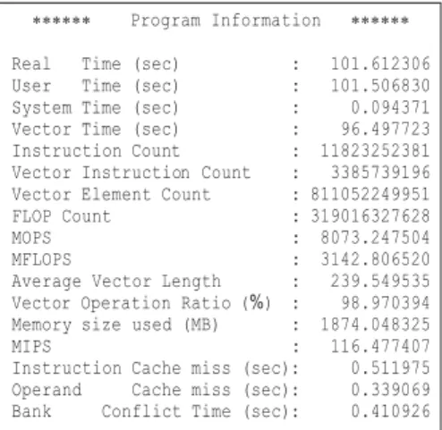
Ftrace and Proginf are available for FORTRAN90/ES and C++/ES. Ftrace is the simple performance analysis function. This function can collect the detailed perform-ance analysis information of each procedure (function) (Fig. 11), but this function should be used only during program tuning because this causes overhead in execution time. Proginf provides the many information concerned with only the overall program execution without any
overhead (Fig. 12). These tools provide performance information as follows;
•Elapsed time
•MFLOPS (Million floating-point operations per
sec-ond)
•Vector operation ratio
•Bank conflict time
•and other performance information
Users can perform tuning efficiently by analyzing these information.
HPFPROF profiler is a tool that analyzes data generat-ed during execution of specially compilgenerat-ed HPF programs. This profiler provides various performance information for tuning works, such as execution count, execution time and information about communications, vector and hard-ware performance. And users can analyze these informa-tion using Graphical User Interface.
Vampir/ES is a performance analysis tool for MPI applications, and this tool displays the application run-time behavior in variety of graphical views.
6. Conclusion
An outline of software of the Earth Simulator (the operating system, Operation Management Software and a programming environment) is presented in this paper.
The operating system and Operation Management Software provide Single System Image (SSI) system operation, system management and job control for the ES system. NQSII, one of the major components of Operation Management Software, plays very important role in executing the batch jobs, and the scheduling algo-rithm used in ES is based on the elapsed time and has achieved high ratio of the node utilization.
As a programming environment, useful languages, libraries and tools are prepared for users to develop well-parallelized programs and to achieve the highest perform-ance. FORTRAN90/ES and C++/ES has advanced capa-bilities of automatic vectorization and microtasking. HPF/ES provides an easy parallel program development environment, and MPI/ES has the highest performance of communication on the ES architecture.
I think that these software provide the efficient opera-tion of the ES system and the comfortable user environ-ment.
Acknowledgments
The author would like to thank the members of the Earth Simulator Center and all of the engineers concerned with the Earth Simulator project.
(This article is reviewed by Dr. Horst D. Simon.)
References
[1] S. Habata, M. Yokokawa and S. Kitawaki, The Earth Simulator System, NEC Research & Development, vol.44, No.1, pp.21 – 26, 2003.
[2] T. Yanagawa, Operating System for the Earth Simulator, NEC Research & Development, vol.44, No.1, pp.43 – 46, 2003.
[3] A. Uno, T. Aoyagi and K. Tani, Job Scheduling on the Earth Simulator, NEC Research & Development, vol.44, No.1, pp.47 – 52, 2003.
[4] E. Miyazaki and K. Yabuki, Integrated Operating Multi-Node System for SX-Series and Enhanced Resource Scheduler, NEC Research & Development, vol.44, No.1, pp. 37– 42, 2003.
[5] M. , H. Ritzdorf, J. L. Träff and F. Zimmermann, The MPI/SX Implementation of MPI for NEC’s SX-6 and Other NEC Platforms, NEC Research & Development, vol.44, No.1, pp.69 – 74, 2003.
[6] H. Uehara, M. Tamura and M. Yokokawa, MPI Performance Measurement on the Earth Simulator, NEC Research & Development, vol.44, No.1, pp.75 – 79, 2003. [7] K. Suehiro, Y. Hayashi, H. Hirokawa and Y. Seo, HPF
and Performance on SX-6/SX-7, NEC Research & Development, vol.44, No. 1, pp.64 – 68, 2003.
[8] H. Sakagami, H. Murai, Y. Seo and M. Yokokawa, 14.9 TFLOPS Three-dimensional Fluid Simulation for Fusion Science with HPF on the Earth Simulator, Proceedings of the ACM/IEEE SC2002 conference, 2002. http://www.sc-2002.org/paperpdfs/pap.pap147.pdf.