Sharif University of Technology
Scientia IranicaTransactions A: Civil Engineering http://scientiairanica.sharif.edu
Simulating structural responses of a generic
AAR-aected arch dam considering seismic loading
M. Lamea
a;and H. Mirzabozorg
ba. Department of Civil Engineering, Kashan Branch-Islamic Azad University, Kashan, P.O. Box 87135/433, Iran. b. Department of Civil Engineering, K.N. Toosi University of Technology, Tehran, P.O. Box 1996715433, Iran. Received 6 December 2015; received in revised form 22 April 2017; accepted 31 July 2017
KEYWORDS Alkali-aggregate reaction;
Concrete arch dams; Finite-element method;
Seismic behavior; Post-earthquake performance.
Abstract.Alkali-Aggregate Reaction (AAR) is a deteriorative phenomenon for concrete that aects the performance of structures. This study focuses on seismic and post-earthquake behaviors of an AAR-aected dam. A computer program is developed for simulating the structural behavior of AAR-aected dams including the seismic and post-earthquake durations. A thin high double-curvature arch dam is selected as a case study and is modelled in a series of analyses within the assumed 30-year operating period. Each analysis includes an earthquake excitation in a dierent specied time. In each analysis, the seismic record is applied to the dam at dierent statuses of AAR progression, considering the proposed ARI index. The results show that AAR aects seismic performance of the dam, i.e., with the AAR progression, the dynamic responses are signicantly changed. On the other side, the eect of earthquake occurrence time on the dam post-earthquake behavior is not noticeable. This may be explained by the linear elastic behavior assigned to the body material in the provided FE model.
© 2018 Sharif University of Technology. All rights reserved.
1. Introduction
The AAR-aected dams show unusual behavior that is intensied with the passage of structure lifetime. This dierent behavior originates from two main factors: the AAR gel expansion and degradation of the concrete mechanical properties. Both of the aforementioned factors are time dependent. On the other side, seis-mic loading is followed by signicant eects on the structural reactions of any dam. With such a point of view, coupling between AAR eects and seismic loading, i.e. seismic loading eects on the performance of the AAR-aected dam and AAR eects on seismic responses, is probable which is followed as a subject for
*. Corresponding author. Tel.: +98 21 8877 9623
E-mail addresses: m [email protected] (M. Lamea); [email protected] (H. Mirzabozorg)
doi: 10.24200/sci.2017.4230
the current research. Several studies have been carried out previously on AAR-aected structures. However, few of them had tendencies towards the dynamic performances.
The earliest phenomenological model presented by Charlwood et al. [1] has been widely used to analyze AAR-aected dams. Some researchers worked on chemo-mechanical modeling of alkali-aggregate re-action [2,3]. Malla and Wieland modelled a rather small arch-gravity dam in both linear and nonlinear conditions. In their research, the volume expansion due to AAR was simulated using equivalent temper-ature and was taken uniform over the whole dam body [4]. Parvini et al. investigated the seismic behavior of an AAR-aected hydraulic structure as a case study. They conducted the dynamic analysis after a period of transient static one (considering AAR phenomenon). The analyses with AAR involved only the pre-earthquake duration; meanwhile, the post-earthquake analysis was not included in the study [5].
Introducing a new phenomenological model for AAR, Saouma and Perotti developed a numerical computer program to simulate structural eects of AAR. Ver-ifying the proposed model, they simulated an AAR-aected arch-gravity dam, which led to accurate and reliable results. In their research, seismic behavior of the structure was not elaborated [6]. Grimal et al. used a numerical model developed by Electricite De France (EDF) and modelled the expansion in damaged structures successfully. The researchers considered the concrete creep, the stresses induced by the AAR gel, and the mechanical damage to predict the experimental behavior of several beams subjected to AAR [7]. Tok-mechi studied the probability of crack distribution and cracked zones percentage due to Normal Alkali Silica Reaction in a sample RCC dam. He used Monte Carlo Method to solve the stochastic system. His study did not deal with seismic loads of the mentioned dam [8]. In the study presented by Jinting et al., the seismic safety of an arch dam suering from aging eects was evaluated using a proposed model. The reduction in the structural safety and intensication of the tensile cantilever stresses were approved during the performed analyses [9]. Based on the Saouma's model, a chemo-damage model was proposed by Pan et al. [10,11], and the model was used to analyze the long-term behavior of AAR-aected gravity dams and arch dams. A more complete review on modeling of AAR-aected cases are presented by Pan et al. [12].
In the current research, a computer code pre-pared previously by the authors was developed for analyzing the AAR-aected structures under seismic excitations. The program is based on the nite-element procedure and is able to analyze the structures in three dierent phases: pre-earthquake static (but transient) phase, dynamic analyses due to seismic loading, and resumption of the static analysis in the post-earthquake phase. During the static phases, AAR progression is numerically simulated following a sigmoid curve based on an adopted comprehensive AAR model. During the earthquake period, no growth in AAR gel or degra-dation in mechanical properties is expected; however, variations in the subsequent eects of the reaction are elaborated. In this regard, a new redistribution of the AAR gel expansion may be expected. This is due to the new imposed connement (i.e., new stress state) during the seismic loading, which leads to changes in the AAR load vector. Furthermore, the material behavior is assumed to be linear elastic. Therefore, when one changes the earthquake excitation time, coupling between AAR and seismic loading and subsequent eects on the post-earthquake responses may be negligible. Nevertheless, the conditions may be dierent during the seismic loading. However, this point of view would be considered during the current research.
2. Governing equations and ground motion loading
Clearly, seismic loading of a dam-reservoir-foundation system is followed by a coupled problem. The coupled mathematical problem should be solved through the numerical procedures, such as Finite-Element method. In the aforementioned system, the Helmoltz equation governs the reservoir medium given as follows [13]:
r2p = 1
C2
@2p
@t2; (1)
where p, C, and t are hydrodynamic pressure, pressure wave velocity in the liquid domain, and time, respec-tively. For solving Eq. (1), the boundary conditions are required to be applied on the reservoir medium [14]. The equations of the dam-foundation (as the structure) and the reservoir take the following form:
[M] 0 [Q]T [G] UP
+
[C] 0 0 [C0] _U_P
+
[K] [Q] 0 [K0] UP
=
8 < :
ff1g [M]
n Ug
o
fF g [Q]TnUgo
9 = ; ; (2) where [M], [C], and [K] are the mass, damping, and stiness matrices of the structure including the dam body and its surrounding foundation medium; [G], [C0],
and [K0] are matrices representing the mass, damping,
and stiness equivalent matrices of the reservoir, re-spectively. Matrix [Q] is the coupling matrix; ff1g is
the vector including both the body and the hydrostatic force; fP g and fUg are the vectors of hydrodynamic pressures and displacements, respectively, and f Ugg is
the ground acceleration vector.
In the current research, all three components of a ground motion record, scaled in DBE (design basis earthquake), are applied simultaneously to the provided nite-element model. For decreasing the computation cost, only the strong motion duration is elaborated. Figure 1 shows the time history of the aforementioned earthquake during strong motion interval.
The conducted seismic analyses include 583 steps with the time interval of 0.02. For computing damping matrix using Rayleigh method, the damping ratio (pro-portional to the structure stiness and mass matrices) is assumed 5%, while and factors are taken as 0.94248 and 0.00199, respectively. It is worth men-tioning that PGA is 0.2 for the horizontal components and 0.11 for the vertical direction based on the dam site specications.
The utilized Newton-Raphson equilibrium iter-ations provide convergence at the end of each load increment within the dened tolerance limits. In this
Figure 1. Scaled strong motion duration of the
earthquake records in three directions: (a) Cross stream, (b) stream, and (c) vertical.
study, for the solid elements with concrete material, the convergence criteria are based on the force and displacement, while elements are based on the pressure for the reservoir uid. For dynamic analyses, the Newmark- method is utilized for the direct integration of the coupled equations along the subsequent time steps.
3. Formulation of the AAR model
For simulating AAR eects within the current devel-oped code, the phenomenological model of Saouma and Perotti is used. This model has a relatively comprehensive formulation involving various aspects of the reaction. It prots by both of state-of-the-art
Figure 2. Reaction progression at a constant temperature [15].
theoretic and new experimental achievements. The reaction kinetics is assumed to follow a sigmoid curve (Figure 2), which is expressed by Eq. (3).
(t; )="AAR(t)="AAR
1 =
1 exp t c()
1 + exp 1 l(;I;fc0)
c()
; (3) where is an index for AAR progression that ranges from 0 to 1, i.e., two limits for minimum and maximum reaction advancements; t is the analysis time (or the dam lifetime); is the internal temperature of AAR-aected material; nally, cand lare the characteristic
and latency times, respectively (see Figure 2 for more details).
AAR has two main eects that aect the time history of structural responses: ination of the AAR gel and degradation of the elastic modulus and tensile strength. Eq. (4) presents a relation for computing the expansion rate in every time step [15].
_"AAR
vol (t)= t(ft0; 1) : c(; fc0) :f(h):(t; ):"1j=0;
(4) where t represents a descendent factor because of
forming macro cracks. Similar eect is exerted by
c due to forming of micro cracks; f(h) is the eect
of moisture deciency (may be taken as unity in the structures such as concrete dams); is attained by Eq. (3); "1is the maximum of free volumetric
expan-sion, measured in the reference temperature [15]. Con-sidering Eq. (4) and through a simple nite dierence method, the gel expansion value in every time step may be computed. The attained expansion value is indeed the free volumetric strain and should be distributed in linear free strains within the provided numerical procedure. This is performed by three corresponding weight factors, wi, so that [15]:
"i= wi"AARV ; i = 1; 2; 3: (5)
princi-pal direction \k" consists of [15]:
Wk = N1W1+ N2W2+ N3W3+ N4W4
=ab1 8 > > < > > :
(a 0
l)(b m0 )
l(b m0 )
0 l0m
(a 0 l)0m
9 > > = > > ;
t8>
> < > > : W1 W2 W3 W4 9 > > = > > ; (6)
According to Figure 3, w1 to w4 correspond to nodes
of the rectangle representing the current stress state; a and b are sides of this rectangle (see [15] for more details).
Following the aforementioned procedure, a vector of free strains is attained which leads to an additional force vector within the utilized nite-element proce-dure.
On the other side, AAR degrades the solidity and tensile strength of the AAR-aected concrete. In this regard, Eqs. (7) and (8) are proposed in the utilized model:
E(t; ) = E0[1 (1 E)(t; )] ; (7)
ft(t; ) = ft;0[1 (1 f)(t; )] ; (8)
where E0 and ft;0 are the initial elastic modulus and
tensile strength, respectively. In addition, E and
f are the corresponding residual fractional values
when "AAR tends to "1AAR. The later equations, along
with Eq. (4), describe the dependency of AAR-aected structure behavior on the dam lifetime. This may lead to dierent seismic behaviors for the structure when it experiences the same excitation at dierent moments
Figure 3. Stress regions for computing stress weight factors [15].
of its lifetime. This is the main challenge considered in the current study.
The currently developed computer program in-volves all of the formulations presented in Sections 2 and 3. The accuracy of this program in simulating AAR-aected concrete structures and seismic load-ing has been previously veried in the separate re-search [14,16,17].
4. Case study: Dez dam
Dez dam is a thin double-curvature high arch dam located in 20 km NE of Andimeshk, Iran (Figure 4(a)). Its height is 203m from the foundation and 190m from the riverbed. For the dam crown cantilever, the thicknesses at the crest elevation and base are 4.5 m and 21 m, respectively. Crest length is 212 m and its altitude is 354 masl. After conducting the optimization program on the dam performance and hydropower gen-eration plants, the reservoir's normal water level was raised up to 352 masl [18]. It is worth noting that the reinforced concrete saddle, referred to as pulvino, was provided between the dam body and foundation rock for facilitating distribution of the applied loads on the surrounding rock. Figure 4(b) shows the downstream view of the Dam and its surrounding environment.
In the provided Finite-Element model, the dam body and its pulvino are modelled using 648 and 144
Figure 4. (a) Satellite photo of Dez dam and lake (Google map, 2017). (b) General view of dam, river, and reservoir [18].
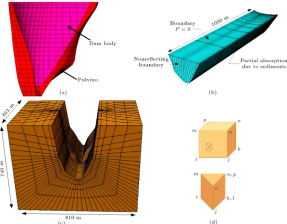
Figure 5. Details of the geometric modelling: (a) Finite-element mesh of the dam body, (b) FE mesh of the reservoir, (c) FE mesh of the foundation, and (d) cubed and prism solid-thermal elements.
elements, respectively (see Figure 5(a)). The dam foundation rock and reservoir aect the seismic analy-sis; they are modelled with 3770 and 3660 elements, respectively. Finally, the total number of elements in the model is 8522 (see Figure 5). The utilized elements for modelling the concrete dam, its pulvino and the foundation rock are 8-node brick elements with 8 integration points. Each node has three translational degrees of freedom in the global directions: x, y, and z. Furthermore, the reservoir is modelled using 8-node uid brick elements. Pressure is the nodal degree of freedom for the uid elements (Figure 5(b)).
Elasticity modulus, Poison's ratio, density and thermal expansion coecient for the dam body con-crete are assumed 40 GPa, 0.2, 2400 kg/m3, and 6
10 6/C, respectively. The moduli of deformations for
the saturated and unsaturated parts of the foundation medium are taken 13 GPa and 15 GPa, respectively. The pressure wave velocity in water is taken 1440 m/s, and the wave reection coecient for the reservoir peripheral boundary is assumed 0.8. All the above-mentioned mechanical parameters were extracted from a comprehensive calibration procedure conducted on the provided model by the second author and his co-workers [18]. Table 1 shows a list of material properties assumed for modeling of the dam in static and dynamic conditions, separately.
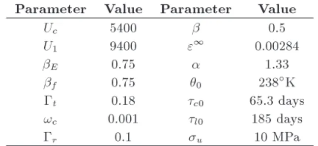
The utilized values for parameters of the AAR
Table 1. Material properties of the mass concrete and foundation rock of Dez arch dam.
Parameter Static Dynamic Econcrete(GPa) 40 46 concrete(kg/m3) 2400 2400
concrete 0.20 0.14
fconcrete
t (MPa) 3.40 5.10
fconcrete
c (MPa) 35.0 36.5
Erock(GPa) 13 15 13 15
rock 0.25 0.25
water(kg/m3) 1000 1000 Cwater(m/s) 1440 1440
model are assumed as presented in Table 2. More details of these parameters may be found in the study by Saouma and Perotti [15].
5. Analyses' results and discussion
Developing the desired program and modeling the case study, a couple of analyses are conducted within the assumed 30-year operation period. All of the analyses involve both of the static (pre-earthquake and post-earthquake analyses) and dynamic phases (during earthquake occurrence) at the same procedure. The specied time for earthquake occurrence is dierent for
Table 2. Values of AAR parameters based on the model of Saouma and Perotti.
Parameter Value Parameter Value
Uc 5400 0.5
U1 9400 "1 0.00284
E 0.75 1.33
f 0.75 0 238K
t 0.18 c0 65.3 days
!c 0.001 l0 185 days
r 0.1 u 10 MPa
each analysis. The performed analyses are named here as follows:
- Case A: Earthquake occurs passing 1 years of the dam lifetime (with ARI=0.2%);
- Case B: Earthquake occurs passing 6 years of the dam lifetime (with ARI=20%);
- Case C: Earthquake occurs passing 9 years of the dam lifetime (with ARI=38%);
- Case D: Earthquake occurs passing 12 years of the dam lifetime (with ARI=57%);
- Case E: Earthquake occurs passing 15 years of the dam lifetime (with ARI=73%);
- Case F: Earthquake occurs passing 26 years of the dam lifetime (with ARI=99%).
It is worth mentioning that occurrence of the earthquake in the above cases is arranged to be on dierent ARI levels. ARI may be a suitable index to evaluate the reaction progression in any AAR-aected dam. This index is proposed by the authors as the weighted average of the reaction kinetics index thorough all elements of the dam body and is computed using Eq. (9):
ARI = Pnel
n=1Vn:RIn
Pnel
n=1Vn
; (9)
where Vn is volume of the nth element, RIn is the
reaction kinetic index of the nth element, and nel is the total number of dam body elements. Figure 6 presents the diagram of ARI versus time for the modelled arch dam. This gure is prepared based on a similar transient static analysis. Indicated in Figure 6, AAR reaches its extreme level after 22 years passing the dam service life. The earthquake excitation times for all of the cases are marked in Figure 6. The analyses cover the occurrence of earthquake in dierent conditions of AAR progression in the considered dam.
It should be noted that a transient thermal analysis is performed before the structural analyses. Solar radiations were modelled in the aforementioned simulations using a precise formulation utilized by the authors during the previous studies [19,20]. Meanwhile,
Figure 6. Diagram of ARI (Average of Reaction kinetic Index) for the analyzed case study.
Figure 7. History of crest displacements in (a) cross-stream direction, (b) horizontal direction, and (c) vertical direction.
the variation of the reservoir surface level was elabo-rated based on the recorded history in the dam site. In all of the cases, seismic loading is assumed to occur in summer, which is commonly known as the critical season for earthquake excitations in arch dams.
from the performed analyses in all of the three direc-tions: x, y, and z.
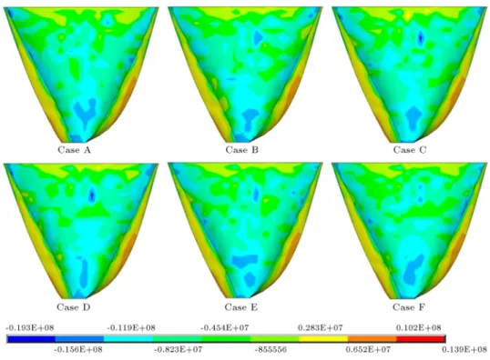
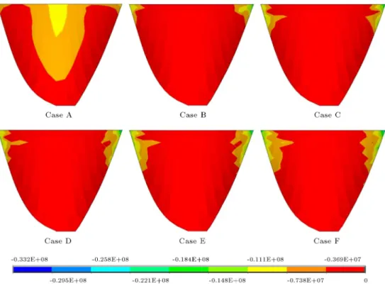
Indicated in the diagrams of Figure 6, it is inferred that the time of earthquake excitation does not aect the time history of post-earthquake crest displacements. However, when the stress contours of
the nal analyses steps (post-earthquake phase) are assessed, some few dierences may be observed (see the contours in Figures 8 and 9).
The rest of the presented results include the struc-tural responses during the seismic loading. Figures 10 and 11 show time history of the crest displacements
Figure 8. Contours of the 1st principal stresses at the last step of the analyses (in DS face, Pa).
Figure 10. History of displacements in US/DS direction for all cases during earthquake (mm) (crest displacements versus analysis steps).
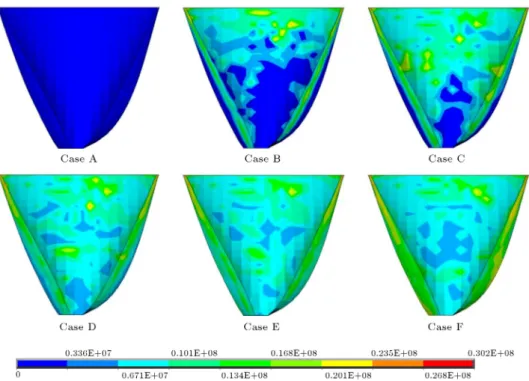
during earthquake for all of the performed analyses. Non-concurrent Envelopes of the 1st and 3rd principal stresses during the earthquake excitation concerning all of the performed seismic analyses are presented in Figures 12 to 15.
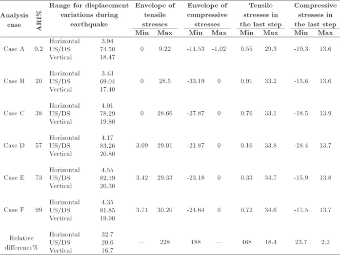
Based on what is observed in Figures 12 to 15, the occurrence of the same earthquake at dierent mo-ments of the lifetime would result in dierent reactions in the considered dam. In Table 3, a summary of the extreme values of Section 5 is presented.
The analyses' results imply that the occurrence of the same earthquake results in dierent seismic reactions in the considered dam. However, the eects are considerably milder when one considers the post-earthquake responses. This may be explained by the assumption of linear elastic behavior for the body mate-rial. Simply, during the short period of the earthquake, there is not enough time for the AAR-aected concrete elements to experience further reduction in the elastic modulus. In other words, when one assumes non-linear behavior for the model, impressibility of the
post-earthquake responses is expected to be intensied. However, this part is left for development of the current research. The results presented in Section 5 show that estimating the responses of an AAR-aected dam is complicated when it experiences earthquake during its service life. Meanwhile, it is indicated that the critical or extreme values of the dierent structural responses do not occur in the same case. This perspective should receive more attention during the future extensions of the current study.
6. Conclusion
Using the new developed code, numerical simulations of AAR-aected dams are possible in both of the static and dynamic phases. Using the aforementioned com-puter program, several analyses, with assumption of the same earthquake excitation, were conducted. Each of the analyses includes simulation of the earthquake excitation at a dierent time step, which corresponds to dierent statuses for the AAR progression. The
Figure 11. History of displacements in US/DS direction for all cases during earthquake (mm) (crest displacements versus analysis steps).
Figure 13. Envelopes of the 1st principal stresses on up-stream face (Pa). Table 3. Summary of the analyses' results during earthquake. Analysis
case ARI%
Range for displacement variations during
earthquake
Envelope of tensile stresses
Envelope of compressive
stresses
Tensile stresses in the last step
Compressive stresses in the last step
Min Max Min Max Min Max Min Max
Case A 0.2 HorizontalUS/DS 74.503.94 0 9.22 -11.53 -1.02 0.55 29.3 -19.3 13.6 Vertical 18.47
Case B 20 HorizontalUS/DS 69.043.43 0 28.5 -33.19 0 0.91 33.2 -15.6 13.6 Vertical 17.40
Case C 38 HorizontalUS/DS 78.294.01 0 28.66 -27.87 0 0.76 33.1 -18.5 13.9 Vertical 19.80
Case D 57 HorizontalUS/DS 83.264.17 3.09 29.01 -21.87 0 0.16 33.8 -18.4 13.7 Vertical 20.80
Case E 73 HorizontalUS/DS 82.194.55 3.42 29.33 -23.18 0 0.33 34.7 -15.9 13.8 Vertical 20.30
Case F 99 HorizontalUS/DS 81.854.35 3.71 30.20 -24.64 0 0.72 34.6 -17.5 13.7 Vertical 19.90
Relative dierence%
Horizontal 32.7
| 228 188 | 468 18.4 23.7 2.2
US/DS 20.6
Figure 14. Envelopes of the 3rd principal stresses on down-stream face (Pa).
Figure 15. Envelopes of the 3rd principal stresses on up-stream face.
modelled AAR-aected case study showed signicant dependency of the seismic responses on the earthquake excitation time. It is observed, prior to almost 50% of the reaction progression, that earthquake eects on the stresses are signicant (Cases A, B, and C);
however, the dependency decreased when earthquake was assumed to occur at any time after passing an ARI of about 50% (Cases C, D, and E). However, the dier-ences were milder when one traced the post-earthquake responses. Highly reliable judgment on the current
conclusions should be left for further considerations. Finally, it may be inferred that evaluating behavior of the AAR-aected dams under seismic loadings is complicated, and only case-by-case simulations may be proposed.
References
1. Charlwood, R.G., Steele, R.R., Solymar, Z.V., and Curtis, D.D. \A review of alkali-aggregate reaction in hydro-electric plants and dams", In Int. Conf. on Alkali-Aggregate Reactions in Hydro-Electric Plants and Dams: New Brunswick, Canada (1992).
2. Huang, M. and Pietruszczak, S. \Modeling of thermo-mechanical eects of alkali-silica reaction", Journal of Engineering Mechanics, 125(4), pp. 476-485 (1999).
3. Ulm, F.J., Coussy, O., Kefei, L., Larive, C. \Thermo-chemo-mechanics of ASR expansion in concrete struc-ture", Journal of Engineering Mechanics, 126(3), pp. 232-242 (2000).
4. Malla, S. and Wieland, M. \Analysis of an arch-gravity dam with a horizontal crack", Computers & Structures, 72(1-3), pp. 267-278 (1999).
5. Parvini, M., Pietruszczak, S., and Gocevski, V. \Seis-mic analysis of hydraulic structures aected by alkali-aggregate reaction: a case study", Canadian Journal of Civil Engineering, 28(2), pp. 332-338 (2001).
6. Saouma, V., Perotti, L., and Shimpo, T. \Stress analysis of concrete structures subjected to alkali-aggregate reactions", ACI Structural Journal, 104(5), pp. 532-541 (2007).
7. Grimal, E., Sellier, A., Multon, S., Le Pape, Y., and Bourdarot, E. \Concrete modelling for expertise of structures aected by alkali aggregate reaction", Cement and Concrete Research, 40(4), pp. 502-507 (2010).
8. Tokmechi, Z. \The probability of RCC dams cracking due to NASR", Aust. J. Basic Appl. Sci., 5(5), pp. 768-775 (2011).
9. Wang, J., Jin, F., and Zhang, C. \Seismic safety of arch dams with aging eects", Science China Technological Sciences, 54(3), pp. 522-530 (2011).
10. Pan, J., Xu, Y., Jin, F., and Zhang, C. \A unied approach for long-term behavior and seismic response of AAR-aected concrete dams", Soil Dynamics and Earthquake Engineering, 63, pp. 193-202 (2014).
11. Pan, J., Feng, Y., Xu, Y., Jin, F., Zhang, C., and Zhang, B. \Chemo-damage modeling and cracking analysis of AAR-aected concrete dams", Science China Technological Sciences, 56(6), pp. 1449-1457 (2013).
12. Pan, J., Feng, Y., Wang, J., Sun, Q., Zhang, C., and Owen, D. \Modeling of alkali-silica reaction in
concrete: a review", Frontiers of Structural and Civil Engineering, 6(1), pp. 1-18 (2012).
13. Mirzabozorg, H. \Staggered solution scheme for three-dimensional analysis of dam reservoir interaction", Dam Engineering, 3, pp. 147-179 (2003).
14. Hariri-Ardebili, M. and Mirzabozorg, H. \Numerical simulation of reservoir uctuation eects on nonlinear dynamic response of concrete arch dams", Advances in Fluid Mechanics VIII (AFM), WIT Press, Algarve, Portugal, pp. 427-438 (2010).
15. Saouma, V. and Perotti, L. \Constitutive model for alkali-aggregate reactions", ACI Materials Journal, 103(3), p. 194 (2006).
16. Lamea, M. and Mirzabozorg, H. \Simulating nonlinear behavior of AAR-aected arch dams including detec-tion of crack proles", Arabian Journal for Science and Engineering, 40(2), pp. 329-341 (2014).
17. Hariri-Ardebili, M. and Mirzabozorg, H. \Feasibility study of Dez arch dam heightening based on nonlinear numerical analysis of existing dam", Archives of Civil Engineering, 59(1), pp. 21-49 (2013).
18. Hariri-Ardebili, M.A. and Mirzabozorg, H. \Feasibility study of Dez arch dam heightening based on nonlinear numerical analysis of existing dam", Archives of Civil Engineering, 59(1), pp. 21-49 (2013).
19. Mirzabozorg, H., Hariri-Ardebili, M., Shirkhan, M., and Seyed-Kolbadi, S. \Mathematical modeling and numerical analysis of thermal distribution in arch dams considering solar radiation eect", The Scientic World Journal, 2014 (2014).
20. Lamea, M. and Mirzabozorg, H. \Evaluating sensitiv-ity of an AAR-aected concrete arch dam to the eects of structural joints and solar radiation", Strength of Materials, 47(2), pp. 341-354 (2015).
Biographies
Mohsen Lamea is now an Assistant Professor at Civil Engineering Department, Islamic Azad University-Kashan Branch, University-Kashan, Iran. He has received his PhD in Structural Engineering from K.N. Toosi University of Technology, Tehran, Iran. His research interests include dam engineering, computational mechanics, and numerical simulations.
Hasan Mirzabozorg is now an Associate Professor at Civil Engineering Department, K.N. Toosi University of Technology, Tehran, Iran. He received his PhD from Sharif University of Technology in Tehran. His research interests are dam engineering, computational mechanics, and numerical simulations.
![Figure 2. Reaction progression at a constant temperature [15].](https://thumb-us.123doks.com/thumbv2/123dok_us/8371472.2223390/3.892.73.413.149.803/figure-reaction-progression-at-a-constant-temperature.webp)
![Figure 3. Stress regions for computing stress weight factors [15].](https://thumb-us.123doks.com/thumbv2/123dok_us/8371472.2223390/4.892.486.818.665.1090/figure-stress-regions-computing-stress-weight-factors.webp)