*Correspondence to Author: Xicun Zhu
College of Resources and Environ-ment, Shandong Agricultural Uni-versity, Tai’an, Shandong; National Engineering Laboratory on Efficient Utilization of Soil and Fertilization, Tai’an, Shandong.
How to cite this article:
Cheng Li, Xicun Zhu, Lulu Gao, Huansan Zhao, Yu Wei, Gengx-ing Zhao. Distributed Storage of Remote Sensing Data Based on Hadoop Platform in Virtual Environ-ment. American Journal of Agricul-tural Research, 2017; 2:2.
eSciPub LLC, Houston, TX USA.
American Journal of Agricultural Research
(ISSN:2475-2002)
Research Article AJAR (2017) 2:2
Distributed Storage of Remote Sensing Data Based on Hadoop
Platform in Virtual Environment
A distributed remote sensing data storage system based on Ha-doop platform is designed to solve the problem of low storage efficiency and low security of mass remote sensing data. Uesd virtualization technology to PC as hardware based virtual com-puting node the Hadoop Cluster required, without increasing the dedicated server clusters and does not change the original PC use conditions, built the Hadoop platform by the virtual machine cluster. Using LandSat-8 satellite image data as the experimen-tal object, through the design of file tree structure, the remote sensing image data according to the band and split into several blocks of image coordinates, combined with the Hadoop distrib-uted file system (HDFS) characteristics of block storage data block, the remote sensing data stored in the distribution of the whole virtual computer cluster in. Build Hadoop platform remote sensing data distributed storage system with low cost.
Key words: Virtualization Hadoop HDFS Remote Sensing Data
Cheng Li1, Xicun Zhu1,2*, Lulu Gao1, Huansan Zhao1, Yu Wei1, Gengxing Zhao1
1College of Resources and Environment, Shandong Agricultural University, Tai’an, Shandong 2National Engineering Laboratory on Efficient Utilization of Soil and Fertilization, Tai’an, Shandong
Introduction
With the rapid development of remote sensing technology, more and more remote sensing data, such as multi-sensor, multi temporal, high spatial resolution and high spectral resolution, are be-coming complex.[1-4] Traditional stand-alone data
storage and processing methods can not meet the needs of rapid processing of massive data. In the process of dealing with a large amount of remote sensing data, the storage, management and query of data has become a very difficult problem. Therefore, it is necessary to explore an efficient way to store remote sensing data in or -der to solve a series of problems.[1, 4-6]
Scholars at home and abroad attempted to es-tablish the remote sensing database and store the remote sensing data in order to store and manage the remote sensing data systematical-ly. The remote sensing database named Micro-soft TerraServer was developed by the MicroMicro-soft Corp in the United States based on SQLServer database software.[7] Wegmuller developed
dif-ferent crop spectral database system accord-ing to the different crop reflectance spectra.[8-9]
Zomer developed wetland spectral database us-ing hyperspectral remote sensus-ing image data.[10]
In China, GeoStar ORACLE database software was developed based on the GeoImageDB im-age database manim-agement system.[11]
However, these remote sensing databases are relational databases (such as ORACLE, MySQL, SQLServer, etc.), which are stored in the form of tables in a single server.[1-6] The main forms of
the remote sensing data are unstructured spec-tral reflectance data, satellite image data and so on. The storage efficiency of these kinds of data is not high in traditional relational database. Moreover, the performance of the database is limited by the hardware and the capacity of the server, which can not adapt to the increasing amount of the remote sensing data, but also has a high security risk.[12-15]
In recent years, with the increasingly maturing of the storage and processing technology, such as Hadoop, of mass data processing, the research-ers began experimenting with remote sensing technology with Hadoop. And the massive remote sensing data in heterogeneous distributed stor-age is studied by using the Hadoop platform, has
achieved remarkable results. In 2011, Kang Jun-feng designed the storage model named C-RSM and management platform named C-RSMP for the high resolution remote sensing image based on the Hadoop and Eucalyptus cloud.[16] On this
basis, Fang Cong designed and developed dis-tribution system of the massive remote sensing data based on peer to peer architecture in 2013.
[17] Lin Jiudui studied and developed a retrieval
system for the massive spatial remote sensing data based on HBase in 2015.[18] Other research
teams have studied in the storage redundancy of the massive remote sensing image[19], efficient
data transmission system[20] and remote sensing
data security mechanism[21], and have developed
their own remote sensing database based on big data or computer cloud platform.
However, the traditional Hadoop cluster needs several to dozens or even hundreds of high per-formance server for hardware based high cost and high speed switching networks with com-plex. System maintenance is more comcom-plex. It is difficult to meet the financial and technical re -quirements of the distributed remote sensing da-tabase based on Hadoop cluster for the ordinary small and medium-sized laboratory. If the use of existing PC in the laboratory without changing the normal use of the way at the same time, us-ing the hardware environment to build Hadoop cluster, will greatly reduce the establishment of the distributed remote sensing database based on Hadoop platform cost and technical difficulty.
[22-23]
The virtualization technology is a virtual number of logic independent computer technology based on the original computer. The virtual computers are independent, without affecting the normal use of the oringinal computer.[22]
In this study, the existing PC in the laboratory can be used to simulate several independent virtual computers based on the virtualization technolo-gy. The use of the virtual computers as Hadoop server cluster, based on no additional dedicated server, set up remote sensing data distributed storage system based on Hadoop platform in a , so as to obtain remote sensing data storage management program.
Introduction to Hadoop
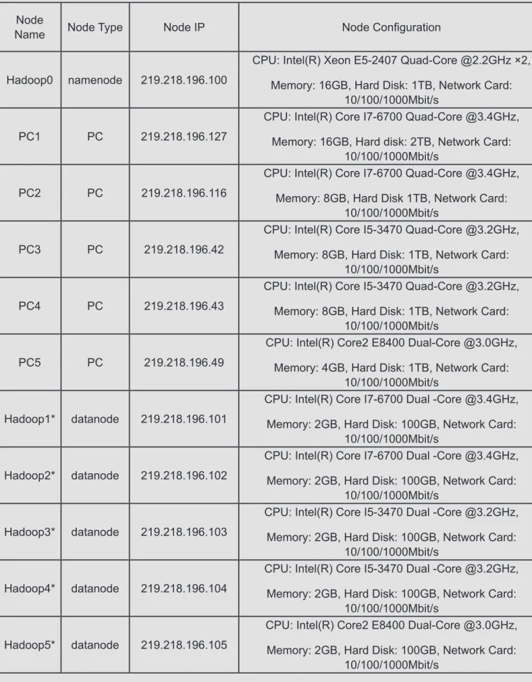
pa-Tab. 1 Hardware configuration of each node
Node
Name Node Type Node IP Node Configuration
Hadoop0 namenode 219.218.196.100
CPU: Intel(R) Xeon E5-2407 Quad-Core @2.2GHz ×2, Memory: 16GB, Hard Disk: 1TB, Network Card:
10/100/1000Mbit/s
PC1 PC 219.218.196.127
CPU: Intel(R) Core I7-6700 Quad-Core @3.4GHz, Memory: 16GB, Hard disk: 2TB, Network Card:
10/100/1000Mbit/s
PC2 PC 219.218.196.116
CPU: Intel(R) Core I7-6700 Quad-Core @3.4GHz, Memory: 8GB, Hard Disk 1TB, Network Card:
10/100/1000Mbit/s
PC3 PC 219.218.196.42
CPU: Intel(R) Core I5-3470 Quad-Core @3.2GHz, Memory: 8GB, Hard Disk: 1TB, Network Card:
10/100/1000Mbit/s
PC4 PC 219.218.196.43
CPU: Intel(R) Core I5-3470 Quad-Core @3.2GHz, Memory: 8GB, Hard Disk: 1TB, Network Card:
10/100/1000Mbit/s
PC5 PC 219.218.196.49
CPU: Intel(R) Core2 E8400 Dual-Core @3.0GHz, Memory: 4GB, Hard Disk: 1TB, Network Card:
10/100/1000Mbit/s
Hadoop1* datanode 219.218.196.101
CPU: Intel(R) Core I7-6700 Dual -Core @3.4GHz, Memory: 2GB, Hard Disk: 100GB, Network Card:
10/100/1000Mbit/s
Hadoop2* datanode 219.218.196.102
CPU: Intel(R) Core I7-6700 Dual -Core @3.4GHz, Memory: 2GB, Hard Disk: 100GB, Network Card:
10/100/1000Mbit/s
Hadoop3* datanode 219.218.196.103
CPU: Intel(R) Core I5-3470 Dual -Core @3.2GHz, Memory: 2GB, Hard Disk: 100GB, Network Card:
10/100/1000Mbit/s
Hadoop4* datanode 219.218.196.104
CPU: Intel(R) Core I5-3470 Dual -Core @3.2GHz, Memory: 2GB, Hard Disk: 100GB, Network Card:
10/100/1000Mbit/s
Hadoop5* datanode 219.218.196.105
CPU: Intel(R) Core2 E8400 Dual-Core @3.0GHz, Memory: 2GB, Hard Disk: 100GB, Network Card:
10/100/1000Mbit/s
per about the GFS (Google File System) which described a distributed file system used for large-scale data intensive and scalable.[24] In
2004, Jeffrey and Sanjay wrote a paper about the MapReduce jointly which provided a new model of algorithm and the generation of a large data set.[25] In 2006, Fay wrote a paper about
BigTable which described a design of distribut-ed structurdistribut-ed data storage system for massive data processing.[26] Hadoop’s predecessor was
the Nutch project hosted by Doug Cutting. In-spired by the three papers from Google, Doug and other researchers in the Nutch project de-signed NDFS, MapReduce and other modules, and later named Hadoop. Hadoop became the top project in Apache in 2008, which marked the platform basically mature. Since then, Hadoop was used by a number of Internet companies.
[27-28] The distributed system represented by
Ha-doop platform provides a solution for the storage and processing of massive heterogeneous data. The Hadoop platform provides a high reliability, high scalability and efficient interface for applica -tions. It is mainly composed of two components of HDFS and MapReduce. In this study, we use HDFS to realize the distributed storage of remote sensing data.
HDFS
HDFS is a distributed file storage system which is based on streaming data access mode to store massive data. Its biggest characteristic is that it can shield the difference of the hardware of the computers in the cluster. The whole cluster is presented as a whole. Data operation, similar to the Linux operating system in the form of data storage, can automatically complete the data re-dundancy backup at the same time. Simple op-eration, high efficiency, safe and reliable.
Block
Similar to the smallest unit of the data in the hard disk read-write named block, HDFS also has the concept of block, but much larger than the hard disk block. The block is the smallest unit of data read-write in Hadoop distributed file system. The default size is 64MB. By designing the data block, you can split large files into a number of small files into the block, the small files are split into the HDFS block, in order to achieve the dis-tributed data storage.
Namenode and Datanode
Namenode and datanode are two kinds of nodes in HDFS system. Where namenode is the man-agement of the whole system, and is responsible for the allocation of data blocks, while recording the data mapping and data block; datanode is the executor in the system, while the HDFS data blocks are actually stored in the physical disk of datanode.
The data storage process
By configuring the system, the Hadoop will be used to integrate all the nodes in the whole com-puter cluster, and the hardware differences be -tween the nodes can be shielded. Set a server as namenode for HDFS, while the remaining nodes are datanode. Set the data block size at the same time. When the user store the remote sensing data to HDFS, namenode split data pre-set according to the size of the block, and then the split data are stored in the datanode block, and the namenode will establish a redundant backup data and block mapping table. When the user reads the data, first of all to the namenode request, namenode query mapping table to de-termine the location of data block in datanodes, and then read out all the data blocks from the datanodes, and reassemble data according to the mapping table. Fig. 1 shows the flow chart for storing data for HDFS.
The computer virtual technology
The computer virtual technology is to abstract the resources of a physical host into logical re-sources, and based on this, a host computer will be able to simulate many independent logical hosts.
Fig. 1 HDFS stored data flow chart
The virtualization technology can facilitate the virtual machine to split, integrate and data migra-tion, so that the entire virtual machine Hadoop cluster is more flexible, more convenient for any node in the cluster system configuration.
Overall system design System architecture design
The system is divided into 5 layers: physical lay-er, virtual laylay-er, data storage laylay-er, data access and operation layer, data presentation layer. The physical layer is hardware and network to-pology. In the traditional Hadoop cluster, the physical layer is composed of a number of spe-cialized servers in a certain network topology. However, in this study the physical layer consists of the existing PC and the switching network in the laboratory.
The virtual layer uses the computer virtualization technology to virtual the physical layer of the PC machine for the formation of a number of Ha-doop cluster logical host.
The data storage layer is installed on the virtual machine cluster Hadoop platform, through the configuration specified namenode and datan -ode, while specifying the size of the data block, the establishment of the Hadoop distributed file system.
A complete set of application interfaces provid-ed by Hadoop data access and operation layer through the realization of HDFS in data access and data CRUD operations.
The data presentation layer is the front-end pro-gram of the system, which can realize the func-tions of data storage, query, browse and down-load through the Linux command line or visual graphical interface.
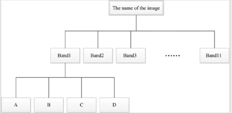
Design of remote sensing data storage model Usually the data volume of a satellite remote sensing image was several hundred megabytes, or even several GB. If fuse the data or operate the band, the volume of data will be greater. The storage efficiency is low in the form of a single image file. According to the theory of HDFS block distributed storage, combined with the technolo-gy of image Pyramid, a whole satellite remote
sensing image is divided into several small blocks according to the band stratified according to the geographic coordinate image, in order for each image encoding of each layer, then each image block is stored in the HDFS data block. When the user accesses the data, the system restructures the original remote sensing image using the image blocks according to the code. The file storage structure is shown in Fig. 2.
System detailed design Experimental data
The experimental data used in this study is the remote sensing data of LandSat-8 satellite, which satellite imaging width is 185 * 185 Km. The LandSat-8 satellite is equipped with Oper-ational Land Imager (OLI) and Thermal Infra-red Sensor (TIRS). OLI includes 8 multispectral bands with spatial resolution of 30 meters and 1 panchromatic band with spatial resolution of 15 meters; TIRS includes two bands with spatial resolution of 100 meters.
The LandSat-8 satellite remote sensing image data format is TIFF format, including 11 image files of bands, a quality evaluation document and a metadata file with TXT format. The quality evaluation document mainly includes the operat-ing environment parameters of the sensor, and the metadata file includes the shooting time, the solar altitude angle and the latitude and longi-tude information.
By analyzing the data format of the LandSat-8 satellite remote sensing image data ,we knew that the metadata file and quality assessment document are the properties file, which can be abstracted as the form of K-V. Typical structured data as they are, the traditional structured data-base such as MySQL can be used to store them by designing the data tables. However the image files are TIFF format. Their data structure is a data cube which is composed of a matrix of the geographic coordinates and a TN value corre-sponding to the pixel. Design file directory ac -cording to the differents of the image file names and the bands, and store them using HDFS. Experiment platform
Tab. 2 The main software installation of each node
Node
Name Operating System Main Software
Hadoop0 Linux CentOS 7 jdk 1.7.0_80, hadoop 2.7.3, MySQL 5.5.27, tomcat 7.0.53 PC1 Windows 7 VMWare Workstation 10, jdk 1.7.0_80, eclipse INDIGO, Xshell 5
PC2 Windows 7 VMWare Workstation 10, Xshell 5
PC3 Windows 7 VMWare Workstation 10, Xshell 5
PC4 Windows 7 VMWare Workstation 10, Xshell 5
PC5 Windows 7 VMWare Workstation 10, Xshell 5
Hadoop1* Linux CentOS 7 jdk 1.7.0_80, hadoop 2.7.3
Hadoop2* Linux CentOS 7 jdk 1.7.0_80, hadoop 2.7.3
Hadoop3* Linux CentOS 7 jdk 1.7.0_80, hadoop 2.7.3
Hadoop4* Linux CentOS 7 jdk 1.7.0_80, hadoop 2.7.3
Hadoop5* Linux CentOS 7 jdk 1.7.0_80, hadoop 2.7.3
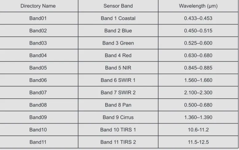
Tab. 3 The relationship between the image data directory name and the sensor band
Directory Name Sensor Band Wavelength (μm)
Band01 Band 1 Coastal 0.433–0.453
Band02 Band 2 Blue 0.450–0.515
Band03 Band 3 Green 0.525–0.600
Band04 Band 4 Red 0.630–0.680
Band05 Band 5 NIR 0.845–0.885
Band06 Band 6 SWIR 1 1.560–1.660
Band07 Band 7 SWIR 2 2.100–2.300
Band08 Band 8 Pan 0.500–0.680
Band09 Band 9 Cirrus 1.360–1.390
Band10 Band 10 TIRS 1 10.6-11.2
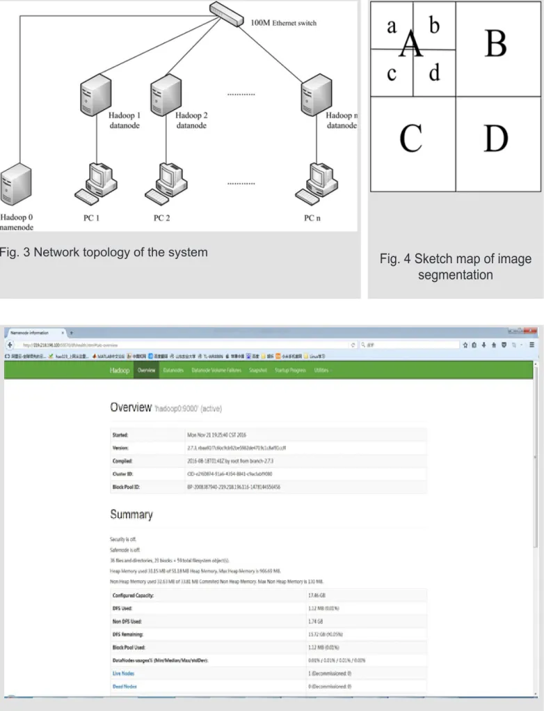
The 2-way sever is a kind of special equipment which is installed Linux operating system, de-ployed Hadoop software and designated as the namenode; 5 PCs are installed Windows oper-ating system, virtual machine software named VMware Workstation. Each PC hosts one virtual machine which is installed Linux operating sys-tem, deployed Hadoop software and designated as the datanode. These nodes are connected by Ethernet switches, with the network communica-tion basing on TCP/IP protocol. The hardware configuration of each node is shown in Tab. 1. The software installation of each node is shown in Tab. 2. The system network topology is shown in Fig. 3.
Remote sensing data storage model Format the HDFS
Initialize the current file system, we can determine the location of a default file system data storage. Complete the operation of format-ing HDFS by the command
$ hadoop namenode –format
Design remote sensing data file tree
Create a folder named RMData in the HDFS root directory, as the root of all remote sensing image data, by the command
$ hadoop dfs –mkdir /RMData
Than create a folder named as the remote sens-ing image file name in RMData.
In the image data root directory, create a series of folders named Band01, Band02 • • • Band11 11 folders, as each band image file storage di -rectory, the corresponding relationship as shown in Tab. 3:
For each band of the image file, the image center is the origin of four equal, as shown in Fig. 4. The image of the upper left, upper right, lower left, lower right of the four image blocks were named A, B, C, D. Create the four sub folders named A, B, C, D in each band folder, and the four im-age blocks of each band are stored in respective folders by name correspondence. For example: A image block of the first band of the XXX imag -es was stored in the folder xxx/Band1/A. If the volume of the data of a single image block is still
large, each image block is divided into four equal parts according to the method.
By this way, the single large data volume image is divided into several small image data blocks. These data blocks are stored in a hierarchical recursive HDFS to form a remote sensing image data file tree.
4.3.3 Input and output remote sensing image data
The namenode in the 2-way server named Ha-doop 0 node was designated as a client, which was connected to each other PC through the Secure Shell (SSH). Any PC in the laboratory can sent commands to the server by the Xshell 5 software. The server and the PC transfer files by the File Transfer Protocol (FTP). At the same time, Hadoop supports that any PC in the net can accesses and manages HDFS through browser.
In the Linux command line mode, access to remote sensing image data resources on the internet by the command:
$ wget
And extract the image data packet by the com-mand:
$ tar –xzvf
Then we can get 11 bands of image files and the metadata file.
After image segmentation using remote sensing data processing software, copy the im-age files from Linux file system to HDFS using the command:
$ hadoop dfs –copyFromLocal
At the same time, managed by the namenode, the data backups automatically. What’s more, a single remote sensing image data packet with a big volume is stored in all datanodes of the Ha-doop cluster distributedly, and the data redun-dancy backup is realized. Users can copy the files from HDFS to local file system by the com -mand:
$ hadoop dfs –copyFromLocal
Fig. 3 Network topology of the system Fig. 4 Sketch map of image
segmentation
the browser.
The Hadoop platform shields the hardware dif-ferences between the nodes in the cluster, and presents it with a whole HDFS. As a data user, what we see is the HDFS composed by the hard disk of the entire datanodes in the Hadoop clus-ter. And the size of the HDFS space is the size sum of the space divided by each datanode. The user does not need to care about each specific data block stored in which hard disk of the PC, and only need to obtain complete remote sens-ing data file tree through the command line or the browser from the HDFS, and download the data to the local computer according to the needs of. When the amount of data continues to increase, you only need to purchase a single hard disk to add to the virtual machine or increase the dat-anode can achieve HDFS expansion, without changing the original HDFS structure or rede-ploy Hadoop system.
Conclusion and discussion Conclusion
The distributed remote sensing data storage sys-tem based on Hadoop platform has been built, through the Computer virtualization technology, based on the hardware of the PC instead of ded-icated server. The conclusions:
(1) The virtualization technology can be used to build a number of virtual Linux server based on the hardware of PC without the need to change the original use of PC;
(2) The virtual Linux server can be used as the computing node of the Hadoop cluster to form a virtual Hadoop cluster;
(3) The virtual Hadoop cluster holds the same function as the traditional Hadoop cluster, which can use HDFS to complete the distributed data storage;
(4) Taking the LandSat-8 satellite image data as the experimental object, combined with the char-acteristics of HDFS Hadoop data block, the re-mote sensing image of the large amount of data is split into several image blocks according to the coordinate and band, to realize the massive re-mote sensing data stored in the file tree.
Discussion
This system provides a flexible and economical way to support for the management and storage of massive remote sensing image data. But the following aspects of the system need to be im-proved:
(1) This system relies on the virtual hardware platform, rather than the traditional physical serv-er clustserv-er, and its pserv-erformance stability needs to be further tested;
(2) This system has not been able to run inde-pendently in the Hadoop cluster, some data pro-cessing work still needs the PC to complete. And the following, we will use the MapReduce pro-gramming model to realize the data processing work Based on the Hadoop platform;
(3) This system user interface is not friendly, that many operations need to manually enter the command to complete. Following, we will use the JavaWeb programming, to build a more friend-ly graphical user interface and convenient, con-venient for users to import and export and data management.
Acknowledgements
This paper was supported by the National Na-ture Science Foundation of China (41671346, 41271369) and Agriculture Big Data Project of Shandong Agricultural University (75016).
References
[1] Huang Feipeng. Design and Implement of Massive Remote Sensing Image Management System[D]. Wuhan: East China Normal University, 2011: 1-3.
[2] Yin Bing. Research of Distributed Remote Sensing Image Processing Based on Hadoop[D]. Wuhan: East China Normal University, 2015: 1-4.
[3] Zhou Tao. Remote Sensing Digital Image Process-ing Methods Based on Hadoop[D]. Changchun: Northeast Normal University, 2013: 1-2.
[4] Xie Changbo. Design and Implementation of Re-mote Sensing Image Storage and Management System[D]. Kunming: Kunming University of Sci-ence and Technology, 2013: 1-4.
[5] Fan Jiang. The Research and Realization of Re-mote Sensing Image Database on IDL[D]. Lan-zhou: Lanzhou University, 2009: 1-7.
2008: 1-6.
[7] Microsoft TerraServer. http://terraserver-usa.com.
[8] Wegmuller U, C Matzler, R Huppi, e tal. Active and passive microwave signature catalogue on bare soil(2-12GHz)[J]. IEEE Geosci. Remote Sensing, 1994, 32(3): 698-702.
[9] Wegmuller U, Sigature research for crop classifi -cation by active and passive microwaves[J]. Int. J. Remote Sensing, 1993, 14(5): 871-883,1993.
[10] Zomer R J, Trabucco A, Ustin S L. Building spec-tral libraries for wetlands land cover classification and hyperspectral remote sensing[J]. Journal of Environmental Management, 2009, 90(7): 2170-2177.
[11] http://www.geostar.com.cn/.
[12] Liu Xiaoli, Xu Pandeng, Zhu Guobin, Li Xue. Par-allel and Distributed Retrieval of Remote Sensing Image Using Hbase and MapReduce[J]. Geogra-phy and Geo-Information Science, 2014, 30(5): 26-30+32.
[13] Chi Ziwen, Zhang Feng, Du Zhenhong, Liu Renyi. A Distributed Storage Method of Remote Sensing Data Based on Image Blocks Organization[J]. Journal of Zhejiang University (Science Edition), 2014, 41(1): 95-99+112.
[14] Cui Jie, Li Taoshen, Lan Hongxing. Design and Development of the Mass Data Storage Platform Based on Hadoop[J]. Journal of Computer Re-search and Development, 2012, 49(Suppl.): 12-18.
[15] Lei Delong, Guo Diansheng, Chen Chongcheng, Wu Jianwei, Wu Xiaozhu. Vector Spatial Data Cloud Storage and Processing Based on Mon-goDB[J]. Journal of Geo-information Science, 2014,16(4): 507-516.
[16] Kang Junfeng. Technologies of Storage and
Ef-ficient Management on Cloud Computing for High
Resolution Remote Sensing Image[D]. Hangzhou: Zhejiang University, 2011: 1-25.
[17] Fang Cong. A Mass Remote Sensing Data Dis-tribution System Which Based on P2P Architec-ture[D]. Hangzhou: Zhejiang University, 2013: 1-11.
[18] Lin Jiudui. A HBase Based Massive Remote Sensing Metadata Search System[D]. Hangzhou: Zhejiang University, 2015: 1-8.
[19] Wang Yanan. Research on the Redundan-cy Mechanism of Remote Sensing Image with
Data[D]. Hangzhou: Zhejiang University, 2012: 1-6.
[21] Hu Wei. The Security Mechanism of Near-infra-red Spectroscopy Big Data under Hadoop Fram-work[D]. Changsha: Hunan Normal University, 2014: 5-12.
[22] Xia Shangyun, Wang Minchao, Zhang Huiran, Dai Dongbo, Xie Jiang, Li Qing, Zhang Wu. Ha-doop Architecture Based-on Virtual Technology of KVM[J]. Microelectronics & computer, 2013, 30(3): 63-66.
[23] Liu Ruiqi, Yang Jie, Gao Zhan, He Zhiqiang. A Resource Scheduling Approach to Improving Data Locality for Virtualized Hadoop Cluster[J]. Journal of Computer Research and Development, 2014, 51(Suppl.): 189-198.
[24] Sanjay Ghemawat, Howard Gobioff, Shun-Tak Leung. The Google File System[J/OL]. http://labs. google.com/papers/gfs.html. 2003.
[25] Jeffrey Dean, Sanjay Chemawat. MapReduce: Simplified Data Processing on Large Clusters[J/ OL]. http://labs.google.com/papers/mapreduce. html. 2004.
[26] Fay Chang, Jeffrey Dean, Sanjay Ghemawat, et al. Bigtable: A Distributed Storage System for Structured Data[J/OL]. http://labs.google.com/pa-pers/bigtable.html. 2006.
[27] Tom White. Hadoop The Definitive Guide[M]. Se -bastopol: O’Reilly Media, 2015: 3-77.