Product Version
Document Organization
Getting Help
Table of Contents
F
ASTF
INDL
INKSHitachi Simple Modular Storage 100
User’s Guide
© 2007 Hitachi Data Systems Corporation, ALL RIGHTS RESERVED
Notice: No part of this publication may be reproduced or transmitted in any form or by any means, electronic or mechanical, including photocopying and recording, or stored in a database or retrieval system for any purpose without the express written permission of Hitachi Data Systems Corporation (hereinafter referred to as “Hitachi Data Systems”). Hitachi Data Systems reserves the right to make changes to this document at any time without notice and assumes no responsibility for its use. Hitachi Data Systems products and services can only be ordered under the terms and conditions of Hitachi Data Systems' applicable agreements. All of the features described in this document may not be currently available. Refer to the most recent product announcement or contact your local Hitachi Data Systems sales office for
information on feature and product availability.
This document contains the most current information available at the time of publication. When new and/or revised information becomes available, this entire document is updated and distributed to all registered users.
Hitachi Data Systems is a registered
trademark and service mark of Hitachi, Ltd., and the Hitachi Data Systems design mark is a trademark and service mark of Hitachi, Ltd. Other company and product names mentioned herein are trademarks of their respective companies. Mention of third-party products is for informational purposes only and
constitutes neither an endorsement nor a recommendation. Hitachi Data Systems assumes no responsibility with regard to the performance or use of these products.
Table of Contents
Preface . . . vii
Document Revision Level . . . .viii
Changes in this Revision. . . .viii
Safety and Warnings . . . .viii
Environmental Notices . . . ix
Intended Audience . . . ix
Product Version. . . ix
Supplemental Documentation . . . ix
Document Organization . . . ix
Related Documents . . . x
Document Conventions . . . x
Convention for Storage Capacity Values. . . xi
Getting Help . . . xi
Support Contact Information . . . xi
HDS Support Web Site . . . xii
Comments . . . xii
1
Introduction . . . 1-1
Overview . . . 1-1
Product Description . . . 1-2
Key Features. . . 1-2
Clear Customer Benefits. . . 1-3
Storage Features . . . 1-3
Holistic Backup and Recovery . . . 1-3
LUN Management . . . 1-4
Security . . . 1-4
Monitoring System Performance . . . 1-5
Supported Host Operating Systems . . . 1-5
Supported Topologies . . . 1-5
Direct Connect Topology . . . 1-6
Switch (Fabric) Topology . . . 1-6
Concepts and Terms . . . 1-7
RAID 6 . . . 1-7
iSCSI . . . 1-7
iSCSI Initiators and Targets . . . 1-7
LUNs . . . 1-8
CHAP . . . 1-8
2
Identifying Hardware Components . . . 2-1
Front Panel Components . . . 2-1
Drive Slots . . . 2-2
Front Panel LEDs. . . 2-2
Power LED . . . 2-2
Ready LED . . . 2-2
Alarm LED . . . 2-2
Warning LED. . . 2-3
Back Panel Components. . . 2-3
iSCSI Gigabit Ethernet Data Ports (PORT A and PORT B). . . 2-4
10/100 Ethernet Management Ports (LAN). . . 2-5
10/100 Ethernet Maintenance Ports (MAINTENANCE ONLY) . . . 2-6
Fans. . . 2-6
Power Supplies . . . 2-7
ON/OFF Switch (MAIN SW) . . . 2-8
Mode Switch . . . 2-8
Top Components. . . 2-9
3
Installing Your Array . . . 3-1
Installation at a Glance . . . 3-2
Preparing Your Site . . . 3-3
Topology Considerations . . . 3-3
Site Considerations . . . 3-3
Rack-Mount Considerations . . . 3-4
Server Considerations . . . 3-4
Safety Considerations . . . 3-5
Unpacking . . . 3-7
Required Items Supplied by the User . . . 3-8
Installing the Hitachi Simple Modular Storage 100 . . . 3-9
Installing on a Table or Shelf . . . 3-9
Rack-Mounting the Hitachi Simple Modular Storage 100 . . . 3-9
Attaching the Front Panel Bezel . . . 3-11
Removing the Front Panel Bezel . . . 3-12
Connecting to the 10/100 Ethernet Management Port . . . 3-13
Connecting to the iSCSI Gigabit Ethernet Data Ports . . . 3-14
Connecting Power . . . 3-15
Verifying Startup Operations . . . 3-16
Configuring and Managing Your Storage . . . 3-17
Installing the Storage Navigator Modular 2 Software . . . 3-17
Logging in to Storage Navigator Modular 2. . . 3-18
Adding Arrays (Add Array Wizard) . . . 3-18
Configuring Array Drives (Initial Setup Wizard) . . . 3-19
Creating Logical Units . . . 3-19
Specifying Mode Parameters . . . 3-20
Installing iSCSI Initiator Software . . . 3-21
Hitachi Simple Modular Storage 100 Host Installation Guide . . . 3-21
4
Maintaining Your Array . . . 4-1
Installing Spares . . . 4-2
Before You Begin. . . 4-2
Checking for Defective Drives . . . 4-2
Installing the Spare Drives . . . 4-5
Caring for Your Hitachi Simple Storage Modular . . . 4-7
Migrating Data . . . 4-7
Moving Your Hitachi Simple Storage Modular . . . 4-8
Before You Move Your Hitachi Simple Modular Storage 100 . . . 4-8
After Your Array is in the New Location . . . 4-8
Storing Your Hitachi Simple Storage Modular 100 . . . 4-9
5
Troubleshooting . . . 5-1
Recovering from Failures . . . 5-2
Troubleshooting Your Array . . . 5-5
A
Upgrading Firmware ... A-1
B
Specifications ... B-1
Mechanical Specifications . . . B-2
Electrical Specifications . . . B-3
Environmental Specifications . . . B-4
Power Cables . . . B-4
Ethernet Specifications. . . B-6
Glossary
Index
Preface
Congratulations on your new Hitachi Simple Modular Storage 100 array.Your Hitachi Simple Modular Storage 100 is a powerful Internet Small Computer System Interface (iSCSI) solution that provides a range of benefits, features, and economics from its ability to use familiar, proven, and widespread networking technologies like Internet Protocol (IP) and Ethernet for storage solutions. Your Hitachi Simple Modular 100 is designed for businesses that want to improve the reliability, availability, serviceability, and
performance of their storage systems.
This guide will assist you in installing, configuring, and maintaining your Hitachi Simple Modular Storage 100. This preface includes the following information:
• Document Revision Level
• Changes in this Revision
• Safety and Warnings
• Environmental Notices • Intended Audience • Product Version • Supplemental Documentation • Document Organization • Related Documents • Document Conventions
• Convention for Storage Capacity Values
• Getting Help
• Comments
Notice: The use of the Hitachi Simple Modular Storage and all Hitachi Data Systems products is governed by the terms of your agreement(s) with Hitachi Data Systems.
Document Revision Level
This section provides a history of the revision changes to this document.
•
Changes in this Revision
This section provides a list of changes from the previous revision to this one. • Not applicable (initial release)
Safety and Warnings
This document uses the following symbols to draw your attention to certain information.
•
Revision Date Description
MK-97DF8061 September 2007 Initial Release
MK-97DF8061-01 November 2007 Revision 1, supersedes and replaces MK-97DF8061-00.
Symbol Meaning Description
•
Tip Tips provide helpful information, guidelines, or suggestions for performing tasks more effectively.
•
Note Notes emphasize or supplement important points of the main text.
•
Caution Cautions indicate that failure to take a specified action could result in damage to the software or hardware.
•
WARNING Warnings indicate that failure to take a specified action could result in loss of data or serious damage to hardware.
•
DANGER Danger warns users of possible injury or death if instructions are not followed.
•cv ELECTRIC SHOCK HAZARD!
This symbol warns users of electric shock hazard. Failure to take appropriate precautions such as not opening or touching hazardous areas of the equipment could result in injury or death.
•
Electrostatic
Sensitive The ESD symbol warns users that the equipment is sensitive to electrostatic discharge (ESD) and could be damaged if users do not take appropriate precautions such as using a grounded wrist strap when touching or handling the equipment.
Environmental Notices
FCC Notice
Federal Communications Commission
This equipment has been tested and found to comply with the limits for a Class A digital device, pursuant to part 15 of the FCC Rules. These limits are designed to provide reasonable protection against harmful interference when the equipment is operated in a commercial environment.This
equipment generates, uses, and can radiate radio frequency energy and, if not installed and used in accordance with the instruction manual, may cause harmful interference to radio communications. Operation of this equipment in a residential area is likely to cause harmful interference, in which case users will be required to correct the interference at their own expense.
Intended Audience
This document is intended for users who are involved in installing, configuring, and operating your Hitachi Simple Modular Storage 100. To use this document, you should have a working knowledge of the following:
• A basic understanding of data storage concepts
• Familiarity with system installation and configuration terminology • An understanding of the host operating system supported by your
Hitachi Simple Modular Storage 100
Product Version
This document revision applies to Hitachi Simple Modular Storage microcode versions 1810/A and higher.
Supplemental Documentation
Release Notes. Please read the Release Notes before installing and/or using this product. The Release Notes are located on the installation CD). They may contain requirements and/or restrictions that are not fully described in this document. The Release Notes may also contain updates and/or corrections to this document.
Document Organization
The following table provides an overview of the contents and organization of this document. Click the chapter title in the first column to go to that chapter. The first page of every chapter or appendix contains a brief list of the contents of that section of the manual, with links to the pages where the information is located.
•
Related Documents
• Hitachi Simple Modular Storage 100 Quick Installation Guide (MK-97DF8059)
• Hitachi Simple Modular Storage 100 Quick Configuration Guide (MK-96DF8090)
• Hitachi Simple Modular Storage 100 Drive Installation Guide (MK-96DF8060)
• Hitachi Simple Modular Storage 100 Auto Migration Assistant Guide
(MK-96DF8066)
• Hitachi Storage Navigator Modular 2 online help
•
Chapter/Appendix
Title Description
Chapter 1, Introduction Provides a brief overview of your Hitachi Simple Modular Storage 100.
Chapter 2, Identifying
Hardware Components Describes the hardware components on your Hitachi Simple Modular Storage 100. Chapter 3, Installing
Your Array
Provides instructions for installing your Hitachi Simple Modular Storage 100.
Chapter 4, Maintaining
Your Array Describes how to install spares and care, transport, and store your Hitachi Simple Modular Storage 100. An overview of migrating data is also provided.
Chapter 5,
Troubleshooting Provides information for identifying and resolving problems. Appendix A, Upgrading
Firmware
Describes how to upgrade your Hitachi Simple Modular Storage 100 firmware.
Appendix B, Factory
Default Settings Shows your Hitachi Simple Modular Storage 100 factory default configuration. Appendix B,
Specifications
Lists your Hitachi Simple Modular Storage 100 specifications.
Glossary Defines the acronyms and special terms used in this document.
Document Conventions
The following table describes the typographic conventions used in this document.
Convention for Storage Capacity Values
Storage capacity values for hard disk drives (HDDs) in Hitachi Data Systems’ storage products are calculated based on the following values: • 1 KB = 1,000 bytes
• 1 MB = 1,0002 bytes • 1 GB = 1,0003 bytes • 1 TB = 1,0004 bytes
For further information on Hitachi Data Systems products and services, please contact your Hitachi Data Systems account team, or visit Hitachi Data Systems online at http://www.hds.com.
Convention Description
Bold Indicates text on a window, other than the window title, including menus, menu options, buttons, fields, and labels.
Italic Indicates a variable, which is a placeholder for actual text provided by the user or system. Example: copy source-file target-file.
Note: Angled brackets (< >) are also used to indicate variables. screen/code Indicates text that is displayed on screen or entered by the user. < > angled
brackets
Indicates a variable, which is a placeholder for actual text provided by the user or system. Italic font is also used to indicate variables. [ ] square
brackets Indicates optional values.
{ } braces Indicates required or expected values.
| vertical bar Indicates that you have a choice between two or more options or arguments.
Getting Help
If you have questions after reading this guide, contact an HDS authorized service provider or visit the HDS support website: http://support.hds.com
Support Contact Information
If you purchased this product from an authorized HDS reseller, contact that reseller for support. For the name of your nearest HDS authorized reseller, refer to the HDS support web site for locations and contact information. To contact the Hitachi Data Systems Support Center, please visit the HDS website for current telephone numbers and other contact information.
http://support.hds.com
Please provide at least the following information about the problem: • Product name, model number, part number (if applicable) and serial
number
• System configuration, including names of optional features installed, host connections, and storage configuration such as RAID groups and LUNs
• Operating system name and revision or service pack number • The exact content of any error message(s) displayed on the host
system(s)
• The circumstances surrounding the error or failure
• A detailed description of the problem and what has been done to try to solve it
• Confirmation that the HDS Hi-Track remote monitoring feature has been installed and tested.
•
HDS Support Web Site
The following pages on the HDS support web site contain other further help and contact information:
• Home Page: http://support.hds.com
NOTE: To help improve the quality of our service and support, your calls may be recorded or monitored.
Comments
Your comments and suggestions to improve this document are greatly appreciated. When contacting HDS, please include the document title, number, and revision. Please refer to specific section(s) and paragraph(s) whenever possible.
• E-mail: [email protected]
• Mail: Technical Writing, M/S 35-10 Hitachi Data Systems 10277 Scripps Ranch Blvd. San Diego, CA 92131
Thank you! (All comments become the property of Hitachi Data Systems
1
Introduction
This chapter provides an overview of your Hitachi Simple Modular Storage 100 array. This chapter covers the following key topics: Overview Product Description
Key Features
Clear Customer Benefits
Storage Features
Supported Host Operating Systems
Supported Topologies
Concepts and Terms
Overview
Your Hitachi Simple Modular Storage 100 is a cost-effective, easily deployable, and fully integrated iSCSI storage solution that allows servers to connect to storage networking using Internet SCSI (iSCSI).
iSCSI is a standard for linking data storage devices over a network and transferring data by carrying SCSI commands over IP networks. On your Hitachi Simple Modular Storage 100, iSCSI disks reside on an expandable RAID-protected volume, but appear to a client machine as a local SCSI drive. Connectivity to the iSCSI disk is established using a software package or PCI card known as an iSCSI initiator, which must be installed on a client machine. The initiator recognizes your Hitachi Simple Modular Storage 100 as a “target portal” and an iSCSI disk as a “target.”
Hitachi Data Systems has qualified a number of iSCSI initiators, network interface cards (NICs), and other devices to interoperate with your Hitachi Simple Modular Storage 100. For the latest information about supported versions and models of iSCSI software and hardware products, please refer to the Hitachi Feature and Interoperability Reports at https://
extranet.hds.com/http://hifirerw.hds.com/HiFire/GuestRegister.jsp.
Product Description
Your Hitachi Simple Modular Storage 100 is available in single- and dual- controller configurations:
• Arrays with a single controller provide two iSCSI data ports and 1 GB of cache.
• Arrays with dual controllers provide four iSCSI data ports and 2 GB of cache.
All iSCSI data ports support 1 Gbps full-duplex Ethernet (1000Base-T) speeds using standard Category 5e or Category 6 Ethernet Local Area Network (LAN) cables.
Both configurations support six, eight, or 12 Serial Advanced Technology Attachment (SATA) or Serial Attached SCSI (SAS) drives. SATA and SAS drives cannot be mixed in the same array.
Key Features
• 1 Gbps full-duplex Ethernet (1000Base-T) iSCSI data ports using standard Category 5e or Category 6 cables
• Available in single- and dual-controller configurations • 1 GB cache per controller
• Provides up to 9 TB of storage
• Supports up to 255 host connections via iSCSI switch
• RAID 6 support allows for two simultaneous drive failures without data loss or downtime
• Modular design supports up to 12 SATA or SAS drives
• Modular design allows two spare drives to be added without having to power-down the array
• Challenge Handshake Authentication Protocol (CHAP) authentication authenticates end-node identities
• iSNS for discovery of devices on the iSCSI network • Redundant (2) power supplies and fans
• Web-based management software featuring a point-and-click GUI and step-by-step wizards that simplify your ability to configure, provision, and manage storage on an as-needed basis
• Array can be configured to send email alerts when a serious event, such as a failure, occurs
Clear Customer Benefits
• Designed from the ground up as a reliable, cost-effective storage solution that is easy for users to install and maintain, without requiring storage expertise
• Proven, third-generation SAN storage technology that delivers enterprise features and remote data protection to small-to-midsize businesses
• High availability with RAID 6 protection to safeguard critical data assets • Installs in minutes, with no single point of failure
• Scalable architecture allows up to two spare drives to be added while the array is running
• Built-in redundancy provide continuous access to data with dual paths from servers to disk drives, and fully redundant power
• Complete suite of quick-start guides, user guides, and Storage Navigator Modular 2 online help ensure you get the most out of your Hitachi Simple Modular Storage 100
Storage Features
Your Hitachi Simple Modular Storage 100 may come with several pre-installed storage features that enable you to simplify your storage tasks. The following sections describe these storage features.
User manuals for the features described in the following sections can be found as PDF files on the documentation CD supplied with your Hitachi Simple Modular Storage 100. If your storage feature requires a license key or code before it can be used, please refer to the Storage Navigator Modular 2 online help for instructions.
Holistic Backup and Recovery
Features
• ShadowImage™ In-system Replication software • Hitachi Copy-on-Write Snapshot software
From accidental file deletions to natural disasters, all kinds of data calamities threaten business operations and escalate the demands for better business practices. The challenge facing most companies is how to minimize the lost revenue and operating expenses these disasters cause. No matter what your company does or what size it is, business continuity matters to you. Your ability to recover data and resume operations depend completely on what you do before the disaster.
NOTE: Some of the features described in the following sections may not be available at the time your Hitachi Simple Modular Storage 100 was shipped. For more information, please refer to the Hitachi Feature and Interoperability Reports at https://extranet.hds.com/http://
Data backups offer critically important benefits, as long as backups are done correctly and consistently. ShadowImage In-system Replication software offers nondisruptive, high-speed data backup operations on a copy of up-to-date production data, while critical applications run unaffected and businesses remain online.
Traditional downtime recovery processes can be labor-intensive and span several hours, during which production data is unavailable. Copy-on-Write Snapshot software rapidly creates point-in-time copies of any data volume within your Hitachi Simple Modular Storage 100 without impacting
application service or performance levels. Because snapshots store only the changed data blocks, the storage capacity required for each copy is
substantially smaller than the source volume, providing significant savings over full cloning methods. The Copy-on-Write Snapshot copies are fully read/write compatible, simplifying rapid data restores, data mining and warehousing, and nondisruptive backup and maintenance procedures.
•
LUN Management
Feature
• LUN Manager
A Logical Unit Number (or LUN) refers to either an entire physical disk, or a subset of a larger physical disk or disk volume. LUNs represent the
“virtualization layer” between the physical disk/volume and applications. A LUN can be used to present a smaller view of the total amount of disk storage available to a server. For example if you partition a drive into small pieces for an application or to accommodate disk limitations of your server’s operating system, each segment would share a common SCSI target ID, with each partition having a unique LUN.
LUN Manager streamlines the processes associated with adding,
configuring, modifying, deleting, and reassigning LUNs to specific paths without having to reboot your array. LUN Manager also lets you assign multiple paths to a single LUN to support alternative path failover, path load balancing, and clustered systems.
Security
Feature
• Password Protection
Your Hitachi Simple Modular Storage 100 offers several data-protection features to protect your critical data assets. Password Protection lets you restrict access to your Hitachi Simple Modular Storage 100 to one registered user at a time.
NOTE: ShadowImage In-system Replication software and Copy-on-Write Snapshot software are available only for Hitachi Simple Modular Storage 100s equipped with dual controllers.
Monitoring System Performance
Feature
• Hitachi Performance Monitor feature
With business infrastructures constantly growing more complex, companies need the knowledge, skills, and tools to quickly identify potential
bottlenecks in each element of the infrastructure and take corrective action, preferably before a problem becomes severe enough to be noticed.
Performance Monitor is an essential tool for planning and analysis of storage resource requirements. It provides detailed, in-depth storage performance monitoring and reporting of your Hitachi Simple Modular Storage 100, including drives, logical volumes, processors, cache, ports, and other resources. It can help you achieve and maintain service-level objectives for performance and availability, identify storage performance bottlenecks, and maximize the utilization of your storage assets. Performance Monitor’s in-depth troubleshooting and analysis reduce the time to resolve storage performance problems.
Supported Host Operating Systems
Your Hitachi Simple Modular Storage 100 works with a number of operating systems, including:
• Microsoft Windows Server 2003, XP, and Vista • Red Hat Linux
• Red Flag Linux • SUSE Linux • Solaris • VMware
The list of supported host operating systems continues to grow. For the latest information, please refer to the Hitachi Feature and Interoperability Reports at https://extranet.hds.com/http://hifirerw.hds.com/HiFire/ GuestRegister.jsp.
Supported Topologies
Your Hitachi Simple Modular Storage 100 is designed to provide disk storage for use by your host servers. At its front end, your Hitachi Simple Modular Storage 100 uses the iSCSI protocol over Ethernet to connect to iSCSI HBAs or NICs installed in your server. This connection can be a direct, point-to-point connection or a switched configuration through an IP storage switch (also known as a “fabric”).
At its back end, your Hitachi Simple Modular Storage 100 contains six, eight, or 12 internal SATA or SAS drives. The drives are preconfigured for RAID 6 and are not intended to be removed from the array. Two spare drive slots are provided for adding capacity, for a total of 12 drives and 9 TB of
Direct Connect Topology
Figure 1-1 shows an example of a direct connection between your Hitachi Simple Modular Storage 100 and host server. In a direct-connect
configuration, the host server can reside up to 100 meters (328 feet) from your Hitachi Simple Modular Storage 100.
•
Figure 1-1: Example of a Direct Connection
Switch (Fabric) Topology
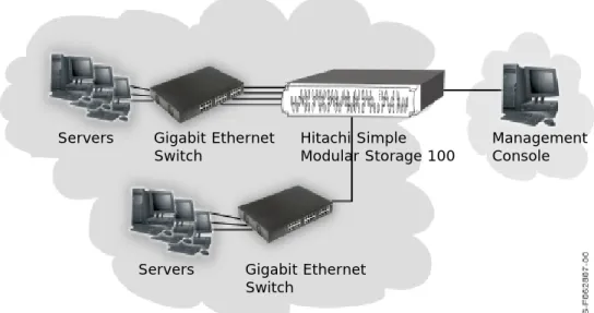
Figure 1-2 shows an example of using your Hitachi Simple Modular Storage 100 in a switch (fabric) configuration. Your Hitachi Simple Modular Storage 100 supports up to 256 connections in a switch configuration. The Storage Area Network shown in the figure is an Ethernet network used to exchange data between your servers and your Hitachi Simple Modular Storage 100.
•
Figure 1-2: Example of a Switch Connection
Servers Hitachi Simple Modular Storage 100
Management Console
Servers Gigabit Ethernet Switch Hitachi Simple Modular Storage 100 Management Console Gigabit Ethernet Switch Servers
Concepts and Terms
This section describes key concepts and terms you will find helpful when using your Hitachi Simple Modular Storage 100. For additional assistance, a
Glossary at the back of this guide defines the technical terms in this guide.
RAID 6
Drives in your Hitachi Simple Modular Storage 100 are preconfigured for RAID 6. RAID 6 is an extension of the RAID 5 array, with a second independent distributed parity scheme. Data and parity are striped on a block level across multiple array members, and a second set of parity is calculated and written across all drives. In this way, RAID 6 delivers enhanced data protection compared with single-parity RAID systems by allowing for two simultaneous drive failures without downtime or data loss. Your Hitachi Simple Modular Storage 100 supports RAID 6 in 6-, 8-, or 12-drive configurations:
• For arrays with six drives, four drives are used for data and two are used for parity.
• For arrays with eight drives, six drives are used for data and two are used for parity.
• For arrays with 12 drives, 9 drives are used for data, two are used for parity, and one acts as a spare in case one of the other drives fails.
iSCSI
Your Hitachi Simple Modular Storage 100 is an iSCSI storage device. iSCSI (pronounced “eye skuzzy”) is an IP-based protocol that leverages the low cost and familiarity of Ethernet and IP networking.
iSCSI links data storage devices over standard Ethernet-based TCP/IP networks using small computer system interface (SCSI) commands. Because iSCSI uses the standard Ethernet infrastructure to provide access to storage “targets,” it is compatible with, and can connect directly to, standard Gigabit Ethernet switches and IP routers. In this way, iSCSI enables low-cost storage access through the mature and predominant Ethernet infrastructure.
iSCSI Initiators and Targets
iSCSI defines a SCSI encapsulation protocol across a TCP/IP connection. As with SCSI, there are two types of components in an iSCSI system: initiators and targets.
An iSCSI initiator is a hardware device — such as an iSCSI host bus adapter (HBA) or TCP/IP offload engine (TOE) — and/or software installed in a server. The iSCSI initiator is the source of iSCSI commands that are sent over the network to the target. As such, it is responsible for:
• Originating iSCSI requests for target discovery and target connection. • Creating the iSCSI packets.
• Handling transmission of the packets and corresponding responses using TCP/IP.
An iSCSI target is a device that receives iSCSI requests originating from an iSCSI initiator. Typically, the target is a drive contained in a storage device, such as your Hitachi Simple Modular Storage 100.
The following steps describe the sequence followed by the iSCSI initiator and target when establishing a “session.”
1. The iSCSI initiator starts a TCP session with a target and tries to log in by sending a list of log-in parameters.
2. The initiator and target may insist on authenticating each other with one of several authentication methods (described next), depending on the system's configuration.
3. After passing the authentication stage, the initiator and target negotiate operating parameters, after which SCSI commands and data can pass between them.
LUNs
Your Hitachi Simple Modular Storage 100 includes several drives, with each drive including many gigabytes of storage. To effectively enable access to this storage, it is organized into smaller portions called logical units or volumes that can be allocated to different resources that want to access the storage.
Each volume itself consists of a numeric address, thereby permitting the storage on your Hitachi Simple Modular Storage 100 to appear as many smaller storage units to the host computers accessing it, enabling more efficient operation. To the server, a volume appears to be a single virtual “disk”.
LUNs can be assigned to hosts, so that a particular volume can be accessed only by designated hosts that have “permission” to access that portion of the storage. This provides enhanced security as the software controlling access to the storage system will only permit access by certain previously defined hosts. While it is somewhat arbitrary how many hosts are permitted to access a given volume, conventionally only one host usually has access rights to a given volume at a given time. As a result, data on the volume is protected against access by hosts or servers other than those previously designated, thereby enhancing the security of the data.
CHAP
The Challenge Handshake Authentication Protocol (CHAP) is a security mechanism that one entity uses to verify the identity of another entity, without revealing a secret password that is shared by the two entities. In this way, CHAP prevents an unauthorized system from using an authorized system's iSCSI name to access storage.
CHAP involves configuring a secret that both your Hitachi Simple Modular Storage 100 and the host server must know. You enable and configure CHAP using Storage Navigator Modular 2. CHAP is not enabled by default, but it is strongly recommended. The Storage Navigator Modular 2 online help describes how to enable and configure CHAP.
The following sequence describes how CHAP works when it is configured and enabled on your Hitachi Simple Modular Storage 100.
1. During negotiations between the iSCSI initiator and target, the initiator sends a “challenge” message to the target.
2. The target responds with a calculated value.
3. The initiator compares the response against its own calculation of the value. If the values match, the initiator acknowledges the
authentication; otherwise, it terminates the connection.
At random intervals, the initiator sends a new challenge to the target and repeats steps 1 through 3 to ensure that it is communicating with the appropriate peer.
2
Identifying Hardware
Components
In This Chapter
This chapter describes the hardware components on your Hitachi Simple Modular Storage 100 array. This chapter covers the following key topics:
Front Panel Components
Back Panel Components
Top Components
Front Panel Components
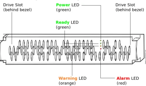
Figure 2-1 shows the hardware components on the front panel of your Hitachi Simple Modular Storage 100.
•
Figure 2-1: Front Panel Components
Drive Slot (behind bezel) Power LED (green) Drive Slot (behind bezel) Ready LED (green) Warning LED
Drive Slots
The front panel of your Hitachi Simple Modular Storage 100 has two drive slots. Each slot can accommodate a spare drive. The spare drive must be of the same type (SATA or SAS) as the other drives in your Hitachi Simple Modular Storage 100.
Front Panel LEDs
The front panel has several light-emitting diodes (LEDs) that show the status of your Hitachi Simple Modular Storage 100.
Power LED
The front panel has a green Power LED that shows when your Hitachi Simple Modular Storage 100 is turned on and receiving power.
Ready LED
The green Ready LED shows when your Hitachi Simple Modular Storage 100 is ready for operation.
Alarm LED
The red Alarm LED shows when your Hitachi Simple Modular Storage 100 is operating normally or has encountered a fatal error.
Table 2-1: Front Panel Power LED
LED Status Description
ON Hitachi Simple Modular Storage 100 is turned on and receiving power. OFF Hitachi Simple Modular Storage 100 is not turned on.
Table 2-2: Ready LED
LED Status Description
ON Normal operation; the array is operational.
Slow Blink Downloaded firmware execution procedure is finished (displayed during maintenance mode).
Fast Blink Firmware is downloading (do not turn off the array).
Table 2-3: Alarm LED
LED Status Description
OFF Normal operation
ON Fatal error. Please visit the Hitachi Web Portal at http:// support.hds.com.
Slow Blink A serious failure has occurred. Please visit the Hitachi Web Portal at http://support.hds.com.
Warning LED
The orange Warning LED shows when your Hitachi Simple Modular Storage 100 is operating normally, has encountered a nonfatal error, and is
upgrading firmware.
Back Panel Components
Figure 2-2 shows the key hardware components on the back panel of a 2-controller Hitachi Simple Modular Storage 100. Components associated with CTL0 are indicated with blue callouts in the following figure, while
components associated with CTL1 are indicated with red callouts. If your Hitachi Simple Modular Storage 100 has a single controller, ignore the components for CTRL 1.
•
Figure 2-2: Key Back Panel Components
Table 2-4: Warning LED
LED Status Description
OFF Normal operation ON or Slow
Blink
Nonfatal error. Array can remain operating.
Fast Blink Flash is being updated with new firmware (do not turn off the array).
NOTE: If your Hitachi Simple Modular Storage 100 has a single controller, ignore the components for CTL1.
Auto Migration Port iSCSI Data Ports
Management Port Maintenance Port Power Receptacle CTL1 CTL0 Fan Power Receptacle
iSCSI Data Ports Auto Migration Port
Fan
MAIN Switch Maintenance Port Management Port
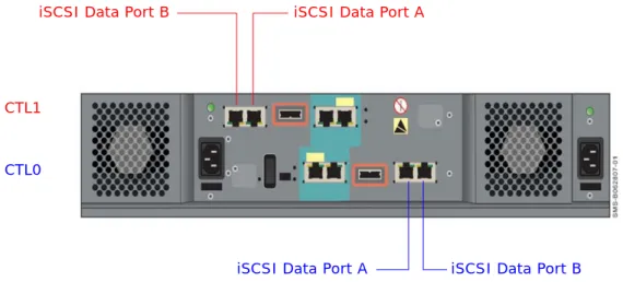
iSCSI Gigabit Ethernet Data Ports (PORT A and PORT B)
Each Hitachi Simple Modular Storage 100 controller has two standard RJ-45 Ethernet iSCSI data ports labeled PORT A and PORT B. Each iSCSI data port provides a 1-Gigabit Ethernet interface for direct or switched
connections to IP hosts that require IP access to storage. Each iSCSI data port accepts a straight-through or cross-over Ethernet cable, and
automatically adjusts to the type of cable used.
Figure 2-3: Location of iSCSI Data Ports on the Back Panel
Each iSCSI data port has an amber port activity LED on the left side of the port and a green link LED on the right side.
Table 2-5: Port Activity LED
LED Status Description
OFF Data is not being sent or received on the port. ON Data is being sent or received on the port.
Table 2-6: Link LED
LED Status Description
OFF Link status error. ON Link status is normal.
iSCSI Data Port A iSCSI Data Port B
CTL1
CTL0
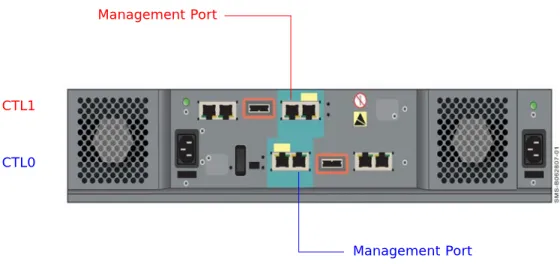
10/100 Ethernet Management Ports (LAN)
Each Hitachi Simple Modular Storage 100 controller has a 10/100BaseT Ethernet management port labeled LAN. These ports connect to the PC acting as the management console.
Using these ports, you can configure and manage your Hitachi Simple Modular Storage 100 using the Hitachi Storage Navigator Modular 2 software on the supplied CD. You can also use the storage features
described under Storage Features on page 1-3 to interact with your Hitachi Simple Modular Storage 100.
These ports accept either a cross-over cable for direct connections to the management port or a straight-through cable if connecting to the
management port through a switch.
Each management port has an amber port activity LED on the left side of the port and a green link LED on the right side (see Table 2-5 on page 2-4
and Table 2-6 on page 2-4).
•
Figure 2-4: Location of Management Ports on the Back Panel NOTE: If you use the Storage Navigator Modular 2 software to configure your Hitachi Simple Modular Storage 100 to send email alerts, be sure the management port can communicate via Ethernet with your mail server. For more information, refer to the Storage Navigator Modular 2 online help.
CTL1
CTL0
Management Port
10/100 Ethernet Maintenance Ports (MAINTENANCE ONLY)
Each Hitachi Simple Modular Storage 100 controller has a 10/100 10/ 100BaseT Ethernet maintenance port labeled MAINTENACE ONLY. These ports are for performing troubleshooting procedures in the unlikely event you encounter a problem with your Hitachi Simple Modular Storage 100. You should not have to use these ports unless instructed to do so by an Hitachi Customer Service Representative.
Each maintenance port has an amber port activity LED on the left side of the port and a green link LED on the right side (see Table 2-5 on page 2-4
and Table 2-6 on page 2-4).
•
Figure 2-5: Location of Maintenance Ports on the Back Panel
•
Fans
The back panel has two fans that provide ventilation for your Hitachi Simple Modular Storage 100. The fans pull air from the front and exhaust to the back. When you install your Hitachi Simple Modular Storage 100, be sure these fans are not blocked and that there is a free flow of air passing from the front of your Hitachi Simple Modular Storage 100. The fans provide redundant cooling. If one fan fails, the other fan runs at a higher speed to compensate for the loss.
•
Figure 2-6: Location of Fans on the Back Panel
CTL1
CTL0
Maintenance Port
Maintenance Port
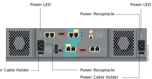
Power Supplies
Your Hitachi Simple Modular Storage 100 comes with two fully redundant power supplies. If one power supply fails, the other one takes over to compensate for the loss.
Each power supply has its own power receptacle that is accessed on the back panel. Both receptacles must be connected to a working AC source using the supplied power cable.
A green LED above each power receptacle blinks when the corresponding power receptacle is connected to a working AC outlet, even if your Hitachi Simple Modular Storage 100 is not powered on; otherwise, the LED is OFF. Below each power receptacle is a holder you can use to secure the power cable after connecting it to your Hitachi Simple Modular Storage 100.
•
•
Figure 2-7: Location of Power Receptacles, LEDs, and Cable Insets
When connecting
CAUTION! When connecting to an AC outlet, do not use an outlet controlled by a wall switch. Otherwise, you will lose access to your Hitachi Simple Modular Storage 100 if the wall switch is
inadvertently turned off.
Power LED Power LED
Power Receptacle
Power Receptacle Power Cable Holder Power Cable Holder
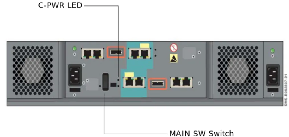
ON/OFF Switch (MAIN SW)
The back panel has an ON/OFF switch labeled MAIN SW that applies power to your Hitachi Simple Modular Storage 100. To apply power, move this switch to the following ON position:
The Power LED on the front panel goes ON.
To turn off your Hitachi Simple Modular Storage 100, move the MAIN SW switch to the following OFF position:
The front panel Power LED and the C-PWR LED on the back panel both go OFF.
•
•
Figure 2-8: Location of MAIN SW Switch on the Back Panel
Mode Switch
The back panel has a mode switch labeled MODE that places a dual-controller Hitachi Simple Modular Storage 100 into migration mode. WARNING! Before you move your Hitachi Simple Modular Storage 100, set the MAIN SW switch to the OFF position and disconnect the power cables from the power receptacles and from the AC source.
C-PWR LED
For normal operation, the mode switch should be in the N position. The E position is used when you need to migrate data from one dual-controller Hitachi Simple Modular Storage 100 to another. The back panel C-PWR LED then goes OFF and the EXT LED goes ON to show that the array is in migration mode. For more information, see Migrating Data on page 4-7.
•
•
Figure 2-9: Location of MODE Switch and EXT LED on the Back Panel
Top Components
The top of your Hitachi Simple Modular Storage 100 may have cautions, product information labels, and/or agency certifications.
NOTE: When you move the MODE switch to the E position, a question mark (?) appears for the status shown for the array in Storage Navigator Modular 2 to show that the array is in migration mode.
EXT LED MODE Switch
3
Installing Your Array
This chapter describes how to install your Hitachi Simple Modular Storage 100 array. This chapter covers the following key topics: Installation at a Glance Preparing Your Site
Safety Considerations
Unpacking
Required Items Supplied by the User
Installing the Hitachi Simple Modular Storage 100
Verifying Startup Operations
Configuring and Managing Your Storage
Installing iSCSI Initiator Software
Installation at a Glance
Table 3-1 describes the steps to follow when installing your Hitachi Simple Modular Storage 100.
Figure 3-1: Installation Roadmap
Table 3-1: Installation Roadmap
Step Description See Page
1. Prepare the site where you intend to install your Hitachi Simple
Modular Storage 100. 3-3
2. Review all safety considerations before you start the installation
process. 3-5
3. Unpack and make sure all items are accounted for and not
damaged. 3-7
4. Obtain the required user-supplied items to perform the
installation. 3-8
5. Install your Hitachi Simple Modular Storage 100. The array can
be installed on a desk or shelf or in a rack. 3-9
6. Verify startup operations. 3-17
7. Configure and manage your storage. 3-18
8. Install iSCSI initiator software. 3-22
9. Consult the Hitachi Simple Modular Storage 100 Host Installation
Guide for your host operating system. 3-22 2. Review All Safety Considerations 3. Unpack the Array 4. Obtain Required Items 1. Prepare Your Site 5. Install the Array 6. Verify Startup Operations 7. Configure & Manage Storage 8. Install iSCSI Initiator 9. See Host Installation Guide
Preparing Your Site
Planning the proper location and layout of your Hitachi Simple Modular Storage 100 is essential for its successful operation. Equipment placed too close together or in an inadequately ventilated area can cause
over-temperature conditions. In addition, poor equipment placement can make the back panel inaccessible.
To ensure normal operation and to avoid unnecessary maintenance, plan your site configuration and prepare your site before installation. The following sections provide guidelines to be observed when preparing your site prior to installing your Hitachi Simple Modular Storage 100.
Topology Considerations
Plan the topology in which your Hitachi Simple Modular Storage 100 will be used. Determine whether you want to set up a dedicated point-to-point configuration for your Hitachi Simple Modular Storage 100 and its iSCSI initiators (a recommended, simple configuration) or include your Hitachi Simple Modular Storage 100 in a shared and potentially complex switch configuration that requires more network expertise and possibly the use of Challenge Handshake Authentication Protocol (CHAP) security.
For more information, see Supported Topologies on page 1-5.
Site Considerations
The site where you install your Hitachi Simple Modular Storage 100 can affect its performance. Therefore, choose a site that:
• Is fairly cool and dry for the acceptable temperature and humidity ranges.
• Is free of strong electromagnetic field generators (such as motors), vibration, dust, and direct exposure to sunlight.
• Provides a sturdy, level surface that can support your Hitachi Simple Modular Storage 100. A fully populated unit weighs approximately 72.6 lbs. (33 kg.).
• Has a power outlet within six feet (1.82 meters) of your Hitachi Simple Modular Storage 100.
• Allows for at least six inches (152.3 mm) of space at the front and back of your Hitachi Simple Modular Storage 100 for ventilation.
• Will not place your Hitachi Simple Modular Storage 100 next to, on top off, or below any device that generates heat or will block the fee flow of air through the array’s ventilation slots.
Rack-Mount Considerations
The following additional considerations must be observed for rack installations (see Figure 2 4):
• Your Hitachi Simple Modular Storage 100 can be mounted in a standard 19-inch rack. The rack-mounting hardware must be carefully selected to properly support the equipment. Follow the instructions in the documentation for the rack.
• The operating ambient temperature of rack-mounted equipment must not exceed the maximum rated ambient temperature indicated in this guide (refer user to Appendix A for more information).
• The air flow clearances specified in this guide must be maintained within the rack.
• The AC supply circuit for rack-mounted equipment must be capable of supplying the total current specified on all the labels of the rack-mounted equipment.
• All AC power supply connections must be properly earthed. To ensure the integrity of the earth connection, special attention must be given to connections that are not directly connected to the branch circuit (for example, power strips).
Server Considerations
• Your Hitachi Simple Modular Storage 100 supports a variety of client operating systems (see Supported Host Operating Systems on page 1-5).
• Be sure your server has an installed iSCSI HBA or NIC with the latest supported Basic Input Output System (BIOS). For the latest HDS-supported iSCSI HBAs and NICs, please refer to Hitachi Feature and Interoperability Reports at https://extranet.hds.com/http://
hifirerw.hds.com/HiFire/GuestRegister.jsp.
• Follow the directions for your iSCSI HBA or NIC to install the card and its appropriate driver(s). Install any required updates, such as service packs, hot fixes, or patches, and reboot the server when the installation is complete.
• Be sure your server is using an HDS-supported iSCSI initiator and driver. For a list of HDS-supported iSCSI initiators and HBAs, please refer to Hitachi Feature and Interoperability Reports at https:// extranet.hds.com/http://hifirerw.hds.com/HiFire/GuestRegister.jsp.
Safety Considerations
Observe the following guidelines to ensure safety. Failure to follow these guidelines could result in bodily injury or damage to your Hitachi Simple Modular Storage 100 chassis or components
• Do not wear loose clothing that could get caught in the chassis or mounting hardware.
• Wear safety glasses when working under conditions that are hazardous to your eyes.
• Do not perform any action that creates a potential hazard to people or makes the equipment or rack unsafe.
• Do not work on the equipment or disconnect cables during a thunderstorm, when wearing a wool sweater or other heavy wool clothing, or when power is applied.
• Disconnect all power before installation.
• Avoid hazards such as moist floor and ungrounded power-extension cables.
• To avoid damage to your Hitachi Simple Modular Storage 100 due to electrostatic discharge (ESD), wear an anti-static wrist strap. Connect the clip to an unpainted part of the array chassis frame to safely channel any static electricity generated by your body to ground. If no wrist strap is available, ground yourself by touching an unpainted part of the array chassis frame.
• A fully populated Hitachi Simple Modular Storage 100 weighs
approximately 72.6 pounds (33 kg) and requires three or more persons to lift the array. Always turn off your Hitachi Simple Modular Storage 100 and unplug all data and power cables before lifting.
• If rack mounting the array, mount the array at the bottom of the rack. If the array is mounted at the top of the rack, the rack may become unstable and fall.
WARNING! During installation, if your Hitachi Simple Modular Storage 100 falls at a high position, a personal injury will be caused. Three or more persons are required to installing the array in a rack above chest level. Perform the positioning, fastening, or other handlings very carefully.
CAUTION! Be sure to perform the rack installation with three or more persons. Work carefully because a single Hitachi Simple Modular Storage 100 can weigh 72.6 pounds (33 kg). Be sure to install the array from the bottom of the rack to prevent the rack from falling. Lift the array up to the height suitable for mounting. Adjust the position of the array, so it is seated in the center of the rack frame. Shift the array onto the rails in the rack frame. When shifting the array, push it in to the end gently.
Unpacking
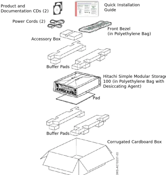
After receiving your Hitachi Simple Modular Storage 100, perform the following steps to ensure that your contents arrived safely.
1. Inspect the outer shipping container for damage during shipping. Report any sign of damage to the appropriate shipping carrier.
2. Remove the contents from the shipping container and check for the following items:
• One Hitachi Simple Modular Storage 100 • Two power cables
• A front bezel
• Product and documentation CDs • One Quick Installation Guide
3. Inspect your Hitachi Simple Modular Storage 100 thoroughly. If you see any signs of damage, contact the shipping carrier.
•
Figure 3-2: Hitachi Simple Modular Storage 100 Package
Quick Installation Guide Product and Documentation CDs (2) Power Cords (2) Buffer Pads Front Bezel
(in Polyethylene Bag)
Hitachi Simple Modular Storage 100 (in Polyethylene Bag with Desiccating Agent)
Pad
Corrugated Cardboard Box Accessory Box
Required Items Supplied by the User
In addition to the contents supplied in your Hitachi Simple Modular Storage 100, the following user-supplied items are required to perform the
installation.
For your Hitachi Simple Modular Storage 100
• An IP address, subnet mask, gateway (if applicable), and Ethernet cable for each iSCSI data port that will connect to your storage network • An IP address and Ethernet cable for each management port
• Two AC outlets (100 V to 120/200 V to 240 V)
For the computer that will act as the iSCSI initiator
• A NIC• An iSCSI initiator driver for your operating system
For the computer that will act as the management console
• An installed NIC with connection to the storage network• 1 GHz Intel processor (2.4 GHz, Intel dual-processor recommended) • At least 1 GB of Random-Access Memory
• At least 1.5 GB of available disk space
• Video resolution of 800 x 600 dots per inch (1024 x 768 or higher recommended)
• One of the following operating systems: • Microsoft Windows XP (Service Pack 2)
• Microsoft Windows 2003 Server (Service Pack 1) • Microsoft Windows 2000 (Service Pack 3/4) • Sun™ Solaris™ v8
• Sun Solaris v9
• Internet access using one of the following browsers • Internet Explorer v6.0
• Mozilla v1.7
•
Rack-mount users require the following additional items
• A standard 19-inch rack.• Mounting hardware for the specific rack being used. • Documentation for the rack and mounting hardware.
Optional Items
An Ethernet switch and Ethernet cable are required to use your Hitachi Simple Modular Storage 100 in a switch (fabric) topology.
•
Installing the Hitachi Simple Modular Storage 100
Installing your Hitachi Simple Modular Storage 100 involves the following steps:
1. Installing your Hitachi Simple Modular Storage 100 on a table or shelf or in a rack. See the sections below.
2. Attaching the front panel bezel. See page 3-12.
3. Connecting to the 10/100 Ethernet management ports. See page 3-14. 4. Connecting to the iSCSI Gigabit Ethernet Data Ports. See page 3-15. 5. Connecting power. See page 3-16.
Installing on a Table or Shelf
If installing your Hitachi Simple Modular Storage 100 on a table or shelf: • Place your Hitachi Simple Modular Storage 100 near an AC power
source.
• Allow enough ventilation space between your Hitachi Simple Modular Storage 100 and other objects in the vicinity.
• Be sure the air vents on the front and back of the your Hitachi Simple Modular Storage 100 enclosure are not blocked.
Rack-Mounting the Hitachi Simple Modular Storage 100
Your Hitachi Simple Modular Storage 100 can be mounted in a standard 19-inch rack. The rack-mount and/or rail kit hardware must be carefully selected to support the equipment properly. Follow the instructions in the documentation for the rack and/or rail kit. For more information, please contact your place of purchase.
The following procedure provides general guidelines to follow when installing your Hitachi Simple Modular Storage 100 in a rack.
•
WARNING! Three or more persons are required to lift your Hitachi Simple Modular Storage 100. Grasp the enclosure from the bottom and lift with both hands. To prevent injury, keep your back straight and lift with your legs, not your back.
WARNING! Three or more persons are required to lift your Hitachi Simple Modular Storage 100. Grasp the enclosure from the bottom and lift with both hands. To prevent injury, keep your back straight and lift with your legs, not your back.
DANGER! Before mount your Hitachi Simple Modular Storage 100 in a rack, be sure the rack is secure and is in no danger of falling over.
•
1. Verify that your Hitachi Simple Modular Storage 100 is turned off. 2. Verify that the MAIN SW switch is in the OFF position.
3. With help from another person, position and hold your Hitachi Simple Modular Storage 100 in the rack. Then secure the array to the rack frame using M5×10 binding screws (one screw at the right and left sides of the array, as shown in Figure 3-3). For more information, refer to the manual for your mounting hardware and rack.
•
•
•
NOTE: Be sure the rack provides sufficient airflow to the front and back of your Hitachi Simple Modular Storage 100 to maintain correct cooling.
WARNING! To prevent bodily injury when mounting or servicing your Hitachi Simple Modular Storage 100 in a rack, you must take special precautions to ensure that the array remains stable. The following guidelines are provided to ensure your safety:
• Perform the rack installation with three or more persons.
• Work carefully because a single Hitachi Simple Modular Storage 100 can weigh 72.6 pounds (33 kg).
• Your Hitachi Simple Modular Storage 100 should be mounted at the bottom of the rack if it is the only unit in the rack.
• Lift the array up to the height suitable for mounting. Adjust the position of the array, so it is seated in the center of the rack frame. Shift the array onto the rails in the rack frame. When shifting the array, push it in to the end gently.
• When mounting your Hitachi Simple Modular Storage 100 in a partially filled rack, load the rack from the bottom to the top, with the heaviest component at the bottom of the rack.
• If the rack is provided with stabilizing devices, install the stabilizers before mounting or servicing your Hitachi Simple Modular Storage 100 in the rack.
WARNING! During installation, if your Hitachi Simple Modular Storage 100 falls at a high position, a personal injury will be caused. Three or more persons are required to installing the array in a rack above chest level. Perform the positioning, fastening, or other handlings very carefully.
•
Figure 3-3: Example of Securing the Array to a Rack
Attaching the Front Panel Bezel
For table and shelf installations, the bezel connects directly to the four ball catches (two on each side) of the Hitachi Simple Modular Storage 100 front panel:
1. Unwrap the front bezel.
2. Holding the side of front bezel with both hands, align it with the four ball catches on the front panel.
3. Gently push the bezel against the catches and front panel until the bezel snaps into place.
Figure 3-4 shows how to attach the bezel for table and shelf installations.
•
Figure 3-4: Attaching the Front Bezel (Table/Shelf Installations) For rack-mount installations, attach the bezel to the front left and right sides of the rack chassis (see Figure 3-5 on page 3-13).
•
Figure 3-5: Attaching the Front Bezel (Rack-Mount Installation)
Removing the Front Panel Bezel
To remove the front bezel, grasp the front bezel and gently pull it toward you until it disengages from the four ball catches (two on each side).
CAUTION! It is important to keep the front panel bezel and rear panel clean (see Caring for Your Hitachi Simple Storage Modular on page 4-7). Otherwise, the array’s internal temperature can increase, causing the array to fail.
Connecting to the 10/100 Ethernet Management Port
For local administrative access to your Hitachi Simple Modular Storage 100, connect the 10/100 Ethernet management port to a PC acting as the management console. You can then use the Storage Navigator Modular 2 software to configure your Hitachi Simple Modular Storage 100.
Initially, you configure your Hitachi Simple Modular Storage 100 by directly connecting a management console PC equipped with a NIC to each
management port using the default IP addresses in Table 3-2. These default IP addresses can be changed using the Storage Navigator Modular 2 software. Thereafter, you can connect the management port(s) to your network and access your Hitachi Simple Modular Storage 100 via the Web using Storage Navigator Modular 2.
1. Connect either end of an Ethernet cable to a NIC installed in a management console.
2. Connect the other end of the cable to the management port(s) labeled LAN on the back of your Hitachi Simple Modular Storage 100 (see
Figure 3-6 on page 3-15).
3. Configure the NIC in the management console to use the subnet 192.168.0.x.
4. Launch your browser and access the management port at the appropriate default IP address:
• For CTL0, use the IP address 192.168.0.16. • For CTL1, use the IP address 192.168.0.17.
5. Perform the configuration activities for that controller.
6. If your Hitachi Simple Modular Storage 100 has a second controller, perform the configuration activities for the other controller using the appropriate IP address in Table 3-2.
•
Table 3-2: Default Management Port IP Addresses
Controller IP Address
Controller 0 192.168.0.16 Controller 1 192.168.0.17
NOTE: If your Hitachi Simple Modular Storage 100 has one controller, ignore the management port on CTL1 in Figure 3-6 on page 3-15.
NOTE: If you are not able to connect, you may need to use a cross-over cable between the management console PC and the management ports.
•
Figure 3-6: Management Ports
Connecting to the iSCSI Gigabit Ethernet Data Ports
The following procedure describes how to connect the iSCSI Gigabit Ethernet data ports to your storage network or server. The default IP addresses for the iSCSI data ports are shown in Table 3-3. These settings can be changed using the Storage Navigator Modular 2 software.
1. On the back panel, insert one end of an Ethernet cable into an iSCSI data port (either PORT A or PORT B)on the back of your Hitachi Simple Modular Storage 100 (see Figure 3-7 on page 3-16 and Figure 3-8 on page 3-16). Connect the other end of the cable to your host system or switch.
2. To connect additional iSCSI data ports to your storage network, repeat step 1 using another Ethernet cable and another available iSCSI data port.
•
•
Management Port on CTL1
Management Port on CTL0
NOTE: If your Hitachi Simple Modular Storage 100 has one controller, ignore the IP addresses for on CTL1 in Table 3-3.
Table 3-3: Default iSCSI Data Port IP Addresses
Controller iSCSI Data Port IP Address
Controller 0 Port A 192.168.0.200 Port B 192.168.0.201 Controller 1 Port A 192.168.0.208 Port B 192.168.0.209
NOTE: If your Hitachi Simple Modular Storage 100 has one controller, ignore the iSCSI data ports on CTL1 in Figure 3-7 on page 3-16.
NOTE: The IP address for your server(s) console must be on the same IP subnetwork (192.168.0.x) as the iSCSI data ports.
•
Figure 3-7: iSCSI Gigabit Ethernet Data Ports
•
Figure 3-8: Connecting an Ethernet Cable
Connecting Power
Your Hitachi Simple Modular Storage 100 comes with two power cables. Both receptacles must be connected to a working AC source using the supplied power cables. This provides redundancy in the unlikely event that one power supply fails.
1. Make sure the MAIN SW switch on the back panel is in the OFF position (see Figure 3-9 on page 3-17).
2. Attach one power cable to the 3-pronged power connectors on the back panel and secure with the power clamp (see Figure 3-9 on page 3-17). Attach the other end to a working AC outlet. Use the holder below the receptacle to secure the power cable. The green LED above the power receptacle blinks.
•
3. We recommend that you repeat step 2 to connect and secure the second power cable.
4. Set the MAIN SW switch to the ON position.
iSCSI Data Ports for CTL1
iSCSI Data Ports for CTL0
NOTE: The AC outlet should not be controlled by a wall switch. Otherwise, the wall switch can accidentally turn off power to your Hitachi Simple Modular Storage 100.
•
Figure 3-9: Attaching the Power Cables
Verifying Startup Operations
To verify that your Hitachi Simple Modular Storage 100 is installed and starts up properly:
1. On the back panel, verify that the green LEDs above each power receptacle are blinking.
2. Set the MAIN SW switch on the back panel to the ON position to apply power.
3. Listen for the fans to start operating and check for airflow.
4. On the front panel, verify that the green Power LED goes on (see
Figure 2-1 on page 2-1).
5. In a few minutes, verify that the green Ready LED on the front panel goes ON (see Figure 2-1 on page 2-1).
•
Power LED Power LED
Power Cable Holder Power Cable Holder MAIN SW Switch
Configuring and Managing Your Storage
After you verify startup operations, your Hitachi Simple Modular Storage 100 is ready for software configuration using the Storage Navigator Modular 2 software on the supplied CD.
With primary goals of simplicity and ease-of-use, the configuration of your Hitachi Simple Modular Storage 100 has been designed to make things obvious for new users from the get-go. To that end, the Storage Navigator Modular 2 software includes the following wizards and point-and-click screens for configuring, provisioning, and managing your storage quickly and easily.
Installing the Storage Navigator Modular 2 Software
The Storage Navigator Modular 2 software is installed on the management console attached to the LAN management port. The console must meet the following minimum requirements:
• Intel processor: 1 GHz (2 GHz or faster recommended) • Memory: At least 1 GB
• Free disk space: 1.5 GB • Video resolution: 1024 x 768
• Microsoft® Windows® XP (Service Pack 2), 2003 Server (Service Pack 1), Windows 2000 (Service Pack 3/4); or Sun Solaris™ v8 or v9
• Browser: Internet Explorer v 6.0 for Microsoft Windows operating systems or Mozilla v1.7 for Solaris operating systems
•
To install Storage Navigator 2:
1. In the management console’s CD-ROM drive, insert the CD containing the Storage Navigator Modular 2 software (see Figure 3-10).
•
Figure 3-10: Inserting the Storage Navigator Modular 2 CD CAUTION! Pop-up blockers must be disabled in the browser.
2. When the installation starts, follow the instructions in the friendly screens that appear. As part of these instructions, you will be asked to either accept the default destination directory where Storage Navigator Modular 2 is to be installed or specify a different location.
Logging in to Storage Navigator Modular 2
1. After you install Storage Navigator Modular 2, log in: http://<IP address of management console PC>:23015/ StorageNavigatorModular/
2. When the login window appears (see Figure 3-11), enter system as the default User ID and manager as the default password ID box.
•
Figure 3-11: Storage Navigator Modular Login Window
•
3. Click the Login button.
Adding Arrays (Add Array Wizard)
When Storage Navigator Modular 2 is launched, it displays all existing arrays contained in its database. The first time it starts, the database does not contain any arrays and Storage Navigator Modular 2 launches the Add Array wizard automatically.
NOTE: If autostart is turned off on the management console, double-click the file SNM2.exe in the SNM2 folder to start the installation.
NOTE: For security, each password character you type appears as a dot (•). We recommend you change the default password to protect your Hitachi Simple Modular Storage 100 against unauthorized access. For more information, refer to the Storage Navigator Modular 2 online help.