Model S3534EC
Full Outage Drive Ride-Thru System
for Variable Frequency AC Drives
Bonitron, Inc.
Nashville, TNAn industry leader in providing solutions for AC drives.
A
BOUT
B
ONITRON
Bonitron designs and manufactures quality industrial electronics that improve the reliability of processes and variable frequency drives worldwide. With products in numerous industries, and an educated and experienced team of engineers, Bonitron has seen thousands of products engineered since 1962 and welcomes custom applications.
With engineering, production, and testing all in the same facility, Bonitron is able to ensure its products are of the utmost quality and ready to be applied to your application.
The Bonitron engineering team has the background and expertise necessary to design, develop, and manufacture the quality industrial electronic systems demanded in today’s market. A strong academic background supported by continuing education is complemented by many years of hands-on field experience. A clear advantage Bonitron has over many competitors is combined on-site engineering labs and manufacturing facilities, which allows the engineering team to have immediate access to testing and manufacturing. This not only saves time during prototype development, but also is essential to providing only the highest quality products.
The sales and marketing teams work closely with engineering to provide up-to-date information and provide remarkable customer support to make sure you receive the best solution for your application. Thanks to this combination of quality products and superior customer support, Bonitron has products installed in critical applications worldwide.
AC
D
RIVE
O
PTIONS
In 1975, Bonitron began working with AC inverter drive specialists at synthetic fiber plants to develop speed control systems that could be interfaced with their plant process computers. Ever since, Bonitron has developed AC drive options that solve application issues associated with modern AC variable frequency drives and aid in reducing drive faults. Below is a sampling of Bonitron’s current product offering.
W
ORLD
C
LASS
P
RODUCTS
Undervoltage Solutions
Overvoltage Solutions
Uninterruptible Power for Drives (DC Bus Ride-Thru) Voltage Regulators Chargers and Dischargers
Energy Storage
Braking Transistors Braking Resistors Transistor/Resistor Combo
Line Regeneration Dynamic Braking for Servo Drives
Common Bus Solutions
Portable Maintenance Solutions
Single Phase Power Supplies 3-Phase Power Supplies
Common Bus Diodes
Capacitor Formers Capacitor Testers
Power Quality Solutions
Green Solutions
1.
I
NTRODUCTION...7
1.1. Who Should Use ... 7
1.2. Purpose and Scope ... 7
1.3. Manual Version and Change Record ... 7
Figure 1-1: Typical S3534EC Ride-Thru System ... 7
1.4. Symbol Conventions Used in this Manual and on Equipment ... 8
2.
P
RODUCTD
ESCRIPTION/
F
EATURES...9
2.1. Related Products ... 9
2.2. Part Number Breakdown ... 10
Figure 2-1: Example of Part Number Breakdown ... 10
Table 2-1: System Voltage Rating Codes ... 10
Table 2-2: Cabinet Styles and Codes ... 10
2.3. General Specifications ... 11
Table 2-3: General Specifications ... 11
2.4. General Precautions and Safety Warnings ... 12
3.
I
NSTALLATIONI
NSTRUCTIONS...13
3.1. Environment ... 13
3.2. Unpacking ... 13
3.3. Mounting ... 13
3.4. Wiring and Customer Connections ... 13
3.4.1. Power Wiring ... 14
Table 3-1: Field Wiring Connections ... 14
Figure 3-1: S3534EC Field Connection Terminal Layout ... 14
Figure 3-2: Typical S3534EC Interconnection with Existing Drive System ... 15
Figure 3-3: S3534EC Drive Ride-Thru System in E61 Cabinet Internal Layout ... 16
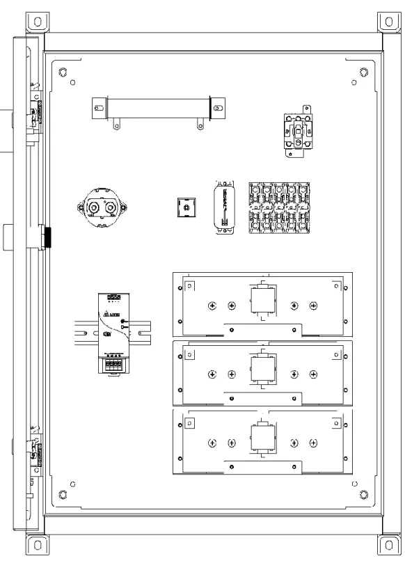
Figure 3-4: S3534EC Drive Ride-Thru System in E63 Cabinet Internal Layout ... 17
4.
O
PERATION...19
4.1. Functional Description ... 19 4.2. Features ... 19 4.2.1. Local Indicators ... 19 4.3. Startup ... 19 4.3.1. Pre-Power Checks ... 194.3.2. Startup Procedure And Checks ... 19
5.
M
AINTENANCE ANDT
ROUBLESHOOTING...21
5.1. Periodic Testing ... 21
5.2. Maintenance Items ... 21
5.2.1. Capacitor Replacement Criteria ... 21
5.3. Troubleshooting ... 21
Table 5-1: Troubleshooting Symptoms ... 21
5.4. Technical Help – Before You Call ... 22
6.
E
NGINEERINGD
ATA...23
6.1. Ratings Charts ... 23
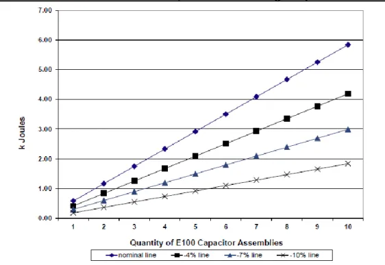
Figure 6-1: Usable kJ with 460V Feed, Drive Undervoltage Trip Point of 550VDC ... 23
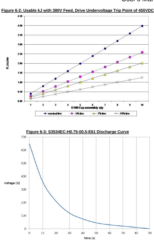
Figure 6-2: Usable kJ with 380V Feed, Drive Undervoltage Trip Point of 455VDC ... 24
Figure 6-3: S3534EC-H0.75-00.5-E61 Discharge Curve ... 24
6.2. Watt Loss ... 25
6.3. Fuse Sizing And Rating ... 25
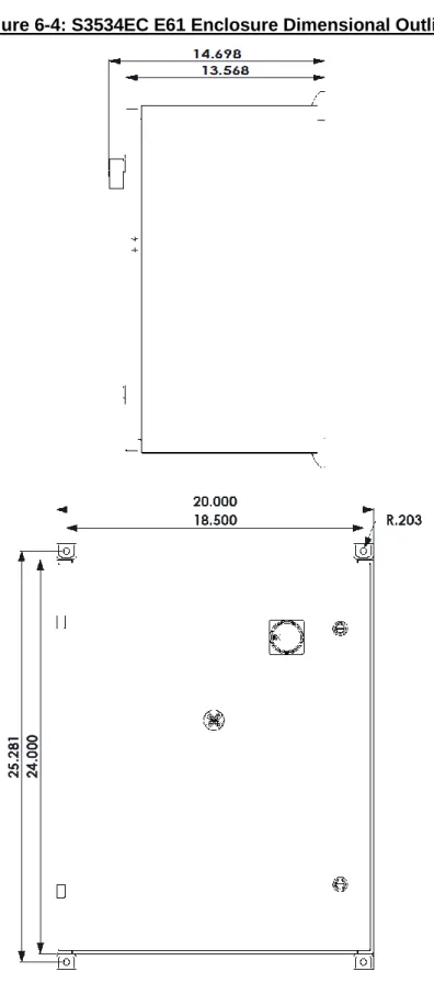
Figure 6-4: S3534EC E61 Enclosure Dimensional Outline ... 26
Figure 6-5: S3534EC E63 Enclosure Dimensional Outline ... 27
Figure 6-6: S3534EC E66 Enclosure Dimensional Outline ... 28
6.5. Block Diagrams ... 29
Figure 6-7: Ride-Thru System Configuration ... 29
7.
A
PPENDICES...30
7.1. Usable Energy Data For Storage Capacitors ... 30
7.2. Calculations ... 30
7.2.1. Determining the Required Capacity of a S3534EC System ... 30
7.2.2. Calculating the Actual Usable Energy of One ASM-3534EC Storage Capacitor ... 31
7.2.3. Determining the Required Number of Storage Capacitors for the S3534EC ... 32
1.
I
NTRODUCTION
1.1.
W
HO
S
HOULD
U
SE
This manual is intended for use by anyone who is responsible for integrating, installing, maintaining, troubleshooting, or using this equipment with any AC Drive System. Please keep this manual for future reference.
1.2.
P
URPOSE AND
S
COPE
This manual is a user’s guide for the Model S3534EC Full Outage Ride-Thru System. It will provide the user with the necessary information to successfully install, integrate, and use the S3534EC system in a variable frequency AC drive system.
In the event of any conflict between this document and any publication and/or documentation related to the AC drive system, the latter shall have precedence.
1.3.
M
ANUAL
V
ERSION AND
C
HANGE
R
ECORD
Rev 01 incorporates the new part number format and additional data. Rev 01a updates include connection clarifications.
The product name and ratings are updated in Rev 01b. An internal wiring drawing is updated in Rev 01c.
Updates to the ratings and manual template were made in Rev 02a. Updates for product redesign made in Rev 03a.
1.4.
S
YMBOL
C
ONVENTIONS
U
SED IN THIS
M
ANUAL AND ON
E
QUIPMENT
Earth Ground or Protective Earth
AC Voltage
DC Voltage
DANGER!
DANGER: Electrical hazard - Identifies a statement that indicates a shock or electrocution hazard that must be avoided.
DANGER!
DANGER: Identifies information about practices or circumstances that can lead to personal injury or death, property damage, or economic loss.
CAUTION!
CAUTION: Identifies information about practices or
circumstances that can lead to property damage, or economic loss. Attentions help you identify a potential hazard, avoid a hazard, and recognize the consequences.
CAUTION!
CAUTION: Heat or burn hazard - Identifies a statement regarding heat production or a burn hazard that should be avoided.
2.
P
RODUCT
D
ESCRIPTION
/
F
EATURES
Variable Frequency Drives (VFDs) are commonly used in industry to improve control over continuous process applications, such as in the textile and semiconductor industries, where very accurate motor speed control is required. Unfortunately, these systems are quite susceptible to problems caused by fluctuations of incoming power, such as AC line voltage sags or outages. Long downtimes as well as large and costly production losses have been experienced due to VFD shutdowns caused by these occurrences.
Bonitron’s model S3534EC series of ride-thru provide protection from AC line voltage sags and outages for AC drive systems that use a fixed DC bus. The S3534 series provides protection from line voltage sags or the momentary loss of one phase by temporarily storing energy internally and releasing it back into the DC bus when needed. This allows the drive to “ride through” these events, maintaining motor speed and torque, without experiencing drive shutdown.
The majority of AC line voltage fluctuations that occur in three-phase distribution systems have a magnitude (decrease from nominal voltage) of less than 50% and duration of less than 2 seconds. The S3534EC incorporates additional capacitive energy reservoirs known as storage capacitors. This allows the ride-thru to supply DC bus power to the inverter during full outages of a predetermined duration in addition to its normal sag protection to allow sufficient time for auxiliary power systems to engage before shutdown occurs. Or, it may allow the drive system to ride through the outage completely, thus avoiding the problems associated with other power supply backup methods.
2.1.
R
ELATED
P
RODUCTS
S3460UR
S
ERIESR
IDE-T
HRUS
YSTEMSComplete systems that use ultracapacitor storage for short term power outages.
S3460BR
S
ERIESR
IDE-T
HRUS
YSTEMSComplete systems that use batteries for longer term power outages.
M3534
S
ERIESR
IDE-T
HRUM
ODULESVoltage regulators used for sag or outage protection of lower power systems.
M5628
B
ATTERY ANDU
LTRACAPACITORC
HARGERSChargers for high voltage storage strings.
M3628
U
LTRACAPACITORS
AFETYD
ISCHARGERSAutomatic discharge for large capacitor storage banks for safety and quick maintenance entry.
2.2.
P
ART
N
UMBER
B
REAKDOWN
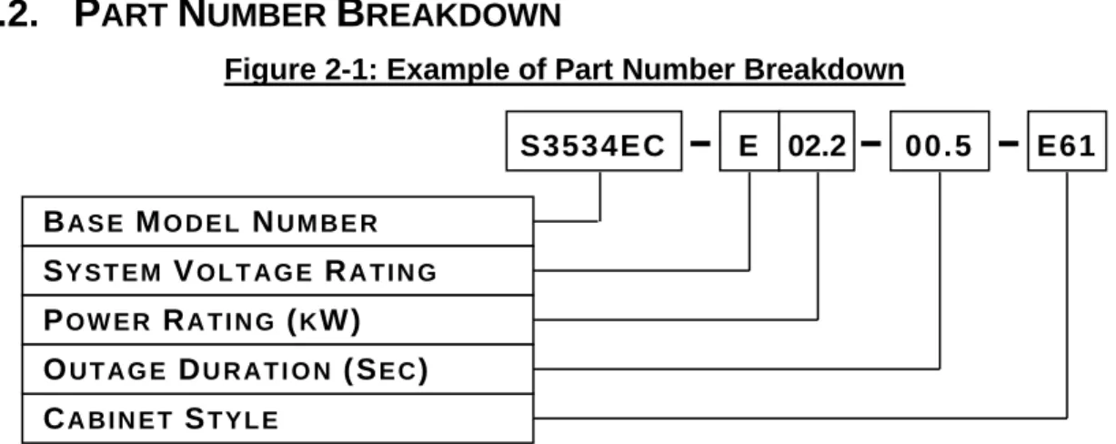
Figure 2-1: Example of Part Number Breakdown
B
ASEM
ODELN
UMBERThe Base Model Number for a full outage AC Input Drive Ride-Thru System without a
M3534R Module is S3534EC.
S
YSTEMV
OLTAGER
ATINGThe System Voltage rating indicates the nominal AC / DC voltage levels of the AC drive system the S3534EC is intended to support. A letter indicates the system voltage.
Table 2-1: System Voltage Rating Codes RATING CODE VOLTAGES (NOMINAL ACLINE /DCBUS) L 230VAC / 320VDC E 380 - 415VAC / 540 - 585VDC H 460VAC / 640VDC
P
OWERR
ATING(
KW)
The Power rating indicates the maximum power in kilowatts that can safely be handled by the S3534EC. This rating is directly represented by a 3-digit value. For instance, the rating for a 2.2kW S3534EC is 02.2.
O
UTAGED
URATION(S
EC)
The Outage Duration indicates the maximum time the S3534EC will support the DC bus at the minimum bus voltage setpoint for the specified system voltage. The time is directly represented in seconds by a 3-digit value. For example, 00.5 in this position represents 0.5 seconds of outage duration.
C
ABINETS
TYLEEnclosure type and size is dependent on the Ride-Thru System specifications. See section 6-4 for dimension information.
Table 2-2: Cabinet Styles and Codes CHASSIS CODE CHASSIS DESCRIPTION
E61 24”(H) x 20”(W) x 12(D) Type-12 wall mount enclosure
E63 30”(H) x 24”(W) x 12(D) Type-12 wall mount enclosure
E66 36”(H) x 30”(W) x 12(D) Type-12 wall mount enclosure
S353 4E C E 02.2 00.5 E61 BA S E MO D E L NU M B E R SY S T E M VO L T A G E RA T I N G PO W E R RA T I N G (KW) CA B I N E T ST Y L E OU T A G E DU R A T I O N ( SE C)
2.3.
G
ENERAL
S
PECIFICATIONS
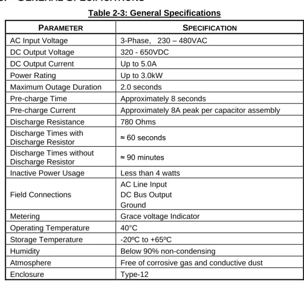
Table 2-3: General Specifications PARAMETER SPECIFICATION
AC Input Voltage 3-Phase, 230 – 480VAC
DC Output Voltage 320 - 650VDC
DC Output Current Up to 5.0A
Power Rating Up to 3.0kW
Maximum Outage Duration 2.0 seconds
Pre-charge Time Approximately 8 seconds
Pre-charge Current Approximately 8A peak per capacitor assembly
Discharge Resistance 780 Ohms
Discharge Times with
Discharge Resistor ≈ 60 seconds
Discharge Times without
Discharge Resistor ≈ 90 minutes
Inactive Power Usage Less than 4 watts
Field Connections
AC Line Input DC Bus Output Ground
Metering Grace voltage Indicator
Operating Temperature 40°C
Storage Temperature -20ºC to +65ºC
Humidity Below 90% non-condensing
Atmosphere Free of corrosive gas and conductive dust
2.4.
G
ENERAL
P
RECAUTIONS AND
S
AFETY
W
ARNINGS
DANGER!
•
H
I G H V O L T A G E S M A Y B E P R E S E N T!
•
N
E V E R A T T E M P T T O O P E R A T E T H I S P R O D U C T W I T H T H E E N C L O S U R E D O O R O P E N!
•
N
E V E R A T T E M P T T O S E R V I C E T H I S P R O D U C T W I T H O U T F I R S T D I S C O N N E C T I N G P O W E R T O A N D F R O M T H E U N I T!
•
A
L W A Y S A L L O W A D E Q U A T E T I M E F O R R E S I D U A L V O L T A G E S T O D R A I N B E F O R E O P E N I N G T H E E N C L O S U R E D O O R.
•
F A I L U R E
T O
H E E D
T H E S E
W A R N I N G S
M A Y
R E S U L T
I N
S E R I O U S
B O D I L Y
I N J U R Y
O R
D E A T H !
CAUTION!
•
T
H I S P R O D U C T W I L L G E N E R A T E H I G H A M B I E N T T E M P E R A T U R E S D U R I N G O P E R A T I O N.
•
T
H I S P R O D U C T S H O U L D B E I N S T A L L E D A C C O R D I N G L Y O N N O N-
F L A M M A B L E S U R F A C E S W I T H C L E A R A N C E S O F A T L E A S T T W O I N C H E S I N A L L D I R E C T I O N S.
•
A
L W A Y S A L L O W A D E Q U A T E T I M E F O R T H E U N I T T O C O O L B E F O R E A T T E M P T I N G S E R V I C E O N T H I S P R O D U C T.
•
B
E F O R E A T T E M P T I N G I N S T A L L A T I O N O R R E M O V A L O F T H I S P R O D U C T,
A L W A Y S R E V I E W A L LA C
D R I V E D O C U M E N T A T I O N F O R P E R T I N E N T S A F E T Y P R E C A U T I O N S.
•I
N S T A L L A T I O N A N D/
O R R E M O V A L O F T H I S P R O D U C T S H O U L D O N L Y B E A C C O M P L I S H E D B Y A Q U A L I F I E D E L E C T R I C I A N I N A C C O R D A N C E W I T HN
A T I O N A LE
L E C T R I C A LC
O D E O R E Q U I V A L E N T R E G U L A T I O N S.
ANY QUESTIONS AS TO APPLICATION, INSTALLATION, OR SERVICE
SAFETY SHOULD BE DIRECTED TO THE EQUIPMENT SUPPLIER.
3.
I
NSTALLATION
I
NSTRUCTIONS
DANGER!
Installation and/or removal of this product should only be performed by a qualified electrician in accordance with National Electrical Code or local codes and regulations.
Proper installation of the S3534EC ride-thru should be accomplished by following the steps outlined below. Be sure to refer to the AC drive instruction manual as these steps are performed. Please direct all installation inquiries that may arise during the installation and startup of this product to the equipment supplier or system integrator. See Section 7.2 for additional installation considerations.
3.1.
E
NVIRONMENT
The installation site for the S3534EC should be chosen with several considerations in mind:
1. The unit has a Type-12 rating and will therefore require some protection from the elements.
2. Conduit access for field wiring may be provided on the top-right surface of the enclosure if desired.
3. The unit will require a minimum clearance of two (2) inches in all directions around it when mounted near a non-heat source.
4. The mounting surface should be clean and dry.
3.2.
U
NPACKING
Upon receipt of this product, please verify that the product received matches the product that was ordered and that there is no obvious physical damage to the unit. If the wrong product was received or the product is damaged in any way, please contact the supplier from which the product was purchased.
3.3.
M
OUNTING
Once the installation site has been selected as outlined above, the unit should be mounted in place. The enclosure is provided with (4) mounting holes.
Mounting holes should be drilled and mounting studs or anchors installed before positioning the enclosure. Mounting hardware is not supplied.
Refer to Section 6 of this manual for the mounting dimensions for the unit.
3.4.
W
IRING AND
C
USTOMER
C
ONNECTIONS
This section provides information pertaining to the field wiring connections of the S3534EC. Actual connection points and terminal numbers of the AC drive system will be found in the documentation provided with that system.
3.4.1.
P
OWERW
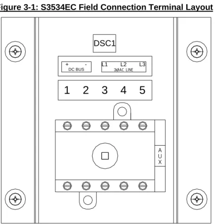
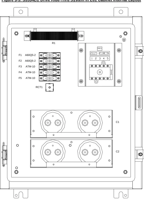
IRINGField connection terminals for the DC Bus output, AC Line input, and Ground are located at the top right of the ride-thru enclosure backplate. See Figure 3-3 for power connection location in the enclosure.
DC
B
USO
UTPUT(DSC1-1,
2)
DC Power Output connections.3-P
HASEAC
L
INEI
NPUT(DSC1-3,
4,
5)
AC Line input connections The AC source needs to be able to supply 8 Amps peak per capacitor module.
G
ROUNDCabinet should be earth grounded to the stud in the upper right corner of the backplate.
Table 3-1: Field Wiring Connections
TERMINAL FUNCTION ELECTRICAL SPECS
MIN WIRE AWG MAX WIRE AWG TORQUE DSC1-1 DC Power Output + 3.0KW 650VDC, 5A 14 AWG 8 AWG 7 - 14 lb-in
DSC1-2 DC Power Output - 650VDC, 5A 7 - 14 lb-in
DSC1-3,4,5 AC Power Input 460VAC, 6.25A 7 - 14 lb-in
GND System Ground Limited by Ring Lug 3/8" 40 - 50 lb-in
Figure 3-1: S3534EC Field Connection Terminal Layout
1
2
3
4
5
+ - L1 L2 L3
3øAC LINE
DC BUS
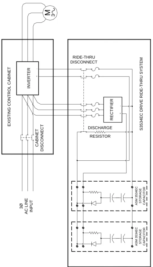
Figure 3-2: Typical S3534EC Interconnection with Existing Drive System S353 4EC DRI VE RIDE-THRU SYSTEM 3Ø AC LIN E INVERT ER EXI STING C ON TR OL CA BINET RE CT IF IER DISCHARGE RESISTOR DISCONNECT RIDE-THRU DISC ONNE CT CABINE T INPUT
M
3 S TOR A GE A SM 3 5 3 4 EC CAP A CITO RFigure 3-3: S3534EC Drive Ride-Thru System in E61 Cabinet Internal Layout 3? AC LINE DC BUS DSC1 C1 R1 C2 RCT1 ATM-10 A60Q5-2 A60Q5-2 ATM-10 ATM-10 F1 F2 F3 F4 F5
4.
O
PERATION
4.1.
F
UNCTIONAL
D
ESCRIPTION
The S3534EC ride-thru system is a passive energy storage reservoir designed to maintain the DC bus of electronic equipment during power sag or loss conditions. During a voltage sag or outage, the inverter DC bus level will be supported by the energy stored within the internal storage capacitors.
Upon application of power to the S3534EC capacitive energy reservoir, its internal storage capacitor will begin to precharge. Storage capacitors used in the ride-thru system incorporate their own slow precharge controls. Complete precharge of the storage capacitor reservoir to nominal DC bus level takes approximately 8 seconds. Once the DC bus has fully precharged to its preset nominal value, the S3534EC is ready to protect from full outages for the duration specified for the system.
The S3534EC ride-thru employs a modular design that allows reservoirs of various capacities to be assembled by connecting fixed storage capacitors in parallel configurations. Each storage capacitor includes its own precharge circuitry, which is designed to open in the event that a capacitor fails within the storage bank. By opening, the precharge circuit limits the energy to the failed capacitor and prevents itself from burning out. In addition, this selective shutdown of a failed capacitor allows the remaining capacitive energy reservoir system to continue functioning at a reduced capacity.
4.2.
F
EATURES
4.2.1.
L
OCALI
NDICATORSA Grace voltage indicator is mounted on the door of S3534EC systems.
4.3.
S
TARTUP
4.3.1.
P
RE-P
OWERC
HECKS1. Ensure power connections have proper torque.
2. Ensure DC bus connections between drive and the S3534EC are the proper polarity.
4.3.2.
S
TARTUPP
ROCEDUREA
NDC
HECKSThe associated drive should be powered up and proven operational before adding the S3534EC.
1. With power already applied to the associated drive, turn on disconnect switch.
5.
M
AINTENANCE AND
T
ROUBLESHOOTING
5.1.
P
ERIODIC
T
ESTING
Yearly testing of the S3534EC capability is recommended for critical applications. Testing can be done by removing power to the drive system, or by verifying the ride-thru capacity through calculation.
1. Remove power to the drive system for the specified outage time.
• Monitor motor speed or watch system parameters. 2. Turn off the disconnect to the S3534EC.
• Monitor capacitor bank voltage with oscilloscope and see typical the capacitor performs a normal discharge.
5.2.
M
AINTENANCE
I
TEMS
5.2.1.
C
APACITORR
EPLACEMENTC
RITERIABonitron Model 3534EC ride-thru uses high quality aluminum electrolytic capacitors and is designed for long life without maintenance. While a typical inverter may require capacitor replacement after a certain time due to the heavy ripple currents, the S3534EC typically is in a standby mode waiting for a power disturbance, and there is no ripple current, thus no heating.
The capacitor manufacturer has given a rating of 10 years MTBF if ambient temp is 50°C, capacitors are held at 100% rated voltage, and caps run full ripple current at 1% duty.
With typical operating conditions of 35°C, caps running at 75% rated voltage, and a duty cycle of one sag per month, Bonitron recommends the capacitors be checked every 5 years or replaced every 10 years.
5.2.1.1.
C
APACITORT
ESTINGP
ROCEDURE1. Remove Lexan covers to gain access to capacitor terminals.
2. Measure voltage across each capacitor and make note for future reference.
• Any voltage difference more than 15% indicates a substantial change in capacitance or leakage.
Example: DC bus = 540V, each series cap = 270V. 15% of 270 = 40.5V cap 1 = 290V cap 2 = 250V.
If any set of capacitors is out of tolerance, remove power and replace both capacitors.
CAUTION!
REPAIRS OR MODIFICATIONS TO THIS EQUIPMENT ARE TO BE PERFORMED BY BONITRON APPROVED PERSONNEL ONLY. ANY REPAIR OR MODIFICATION TO THIS EQUIPMENT BY PERSONNEL NOT APPROVED BY
BONITRON WILL VOID ANY WARRANTY REMAINING.
5.4.
T
ECHNICAL
H
ELP
–
B
EFORE
Y
OU
C
ALL
If possible, please have the following information when calling for technical help:
• Exact model number of affected units
• Serial number of unit
• Name and model number of attached drives
• Name of original equipment supplier
• Brief description of the application
• The AC line to line voltage on all 3 phases
• The DC bus voltage
• KVA rating of power source
• Source configuration Wye/Delta and grounding
This information will help us support you much more quickly. Please contact us at (615) 244-2825 or through www.bonitron.com
6.
E
NGINEERING
D
ATA
6.1.
R
ATINGS
C
HARTS
To provide full outage protection, 3534EC storage capacitors are required. Figures 6-1 through 6-3 provide data based on the number of storage capacitors used and the system AC line or DC bus voltage level.
Figure 6-2: Usable kJ with 380V Feed, Drive Undervoltage Trip Point of 455VDC
6.2.
W
ATT
L
OSS
Less than 2 watts per capacitor assembly.
6.3.
F
USE
S
IZING
A
ND
R
ATING
AC Line input: (3) ATM-10 – 1 fuse per phase. DC Bus output: (2) A60Q5-2 – 1 fuse per leg.
6.4.
D
IMENSIONS AND
M
ECHANICAL
D
RAWINGS
6.5.
B
LOCK
D
IAGRAMS
Figure 6-7: Ride-Thru System Configuration
SINGLE CABINET POWERED FROM AC LINE USING ELECTROLYTIC CAP RESERVOIR
2.5KW & BELOW, 0 - 0.5 SECOND, 100% OUTAGE PROTECTION
AC LIN E 3 PHASE VFD M CAPACITOR DC LINK BANK ELECTROLYTIC 3534EC
7.
A
PPENDICES
7.1.
U
SABLE
E
NERGY
D
ATA
F
OR
S
TORAGE
C
APACITORS
This section provides data pertaining to the amount of available usable energy for DC bus voltage support provided by S3534EC Systems as well as the effect that drive system AC Line / Low Voltage trip levels have on these ratings.
The usable energy available from a capacitive energy reservoir, such as the ASM 3534EC-E100 Storage Capacitor used in the S3534EC Ride-Thru System, is the difference between the reservoir’s total stored energy when charged to the normal DC bus level and its remaining energy when the DC bus drops to the low voltage trip setting of the drive system. Accordingly, the actual usable energy of the reservoir can be optimized through higher AC line levels and/or lower drive low voltage trip settings. While an inverter may continue to run at lower voltages, the output power is decreased to the motor.
7.2.
C
ALCULATIONS
This section provides the calculations required to determine the optimum number of storage capacitors to be used when configuring a S3534EC Drive Ride-Thru System. There are three important calculations that must be made to properly size the system. First, the necessary capacity of the system to adequately support the drive system must be determined. Next, the actual usable energy level of the storage capacitor type to be used in the system must be calculated based on drive system parameters. Finally, the first two calculations are used to determine the optimum number of storage capacitors to include in the system configuration. Each of these calculations is detailed below.
7.2.1.
D
ETERMINING THER
EQUIREDC
APACITY OF AS3534EC
S
YSTEMThe capacity or USABLE ENERGY rating (in kJ) of a S3534EC DC bus support system required to support a given drive system can be determined by multiplying the drive or load rating (in kW) by the duration (in seconds) of the outage to be protected against. Keep in mind that the S3534EC is rated for 2.2kW maximum. For load ratings greater than 2.2kW or 3kJ, the M3534CR may be added for a more cost effective solution.
The following formula is used to determine the required capacity (in kJ or hps) of a S3534EC System:
Capa city (kJ) = Load (kW) x Dur atio n (secon ds)
Capa city (h ps) = Load (h p) x Durat ion (seconds)
To be sure that the S3534EC will always be sufficiently sized for the drive system, use the power rating of the drive in the calculation. Since the load on the drive will not exceed the drive rating, the calculated capacity will always be sufficient. To determine capacity for a specific application where the drive may be oversized for the actual load, the power rating of the actual load may be used.
7.2.2.
C
ALCULATING THEA
CTUALU
SABLEE
NERGY OFO
NEASM-3534EC
S
TORAGEC
APACITORIn order to provide a reliable general guideline for properly sizing a model
S3534EC DC Bus Support system, the USABLE ENERGY ratings for
ASM-3534EC-E100 Storage Capacitors were calculated based on the combined conservative assumptions of a low AC line input level and relatively high drive Low Voltage trip setpoint. This helps to ensure that the S3534EC system will adequately perform under actual field conditions.
However, to more accurately determine the actual USABLE ENERGY of an ASM-3534EC Storage Capacitor when used for support of a drive, 3 specific values must be known:
1. the capacitance of the Storage Capacitor (10,000uF for the ASM-3534EC-E100)
2. the normal operating DC bus voltage for the drive system 3. the low voltage trip setpoint of the drive
The following equation is used to calculate Usable Energy (in joules) of a capacitive energy reservoir:
EU = ES – ER
Where
EU is the actual Usable energy (in joules) available from the capacitive reservoir to provide DC bus support during outage or dip situations.
ES is the total Stored energy (in joules) in the capacitive reservoir during normal operating conditions.
ER is the total unused Remaining energy (in joules) in the capacitive reservoir after the drive unit has tripped due to low voltage conditions. Before the Usable Energy (EU) can be calculated, it is necessary to first calculate the Stored Energy (ES) and Remaining Energy(ER) values.
The following equation is used to calculate both Stored and Remaining Energy (in joules) for the capacitive energy reservoir:
E = ½CV2
Where
E is energy (in joules)
Once the Stored and Remaining energy calculations have been completed, simply plug the values into the Usable energy equation and convert the results to horsepower-seconds, using the conversion factor below, to arrive at the Usable Energy rating.
If jou le s = watt -seco nd s
and watts x 0.001 341 = horsep ower
then jou le s x 0.001 341 = horsep ower -s eco nds
7.2.3.
D
ETERMINING THER
EQUIREDN
UMBER OFS
TORAGEC
APACITORS FOR THES3534EC
Now that a value for ‘Usable Energy’ has been determined for a single Storage Capacitor, divide this number into the previously calculated ‘Required Capacity’ value to determine the required number of Storage Capacitors to be included in the S3534EC system.
Req’d Capacity(hps) Storage Capac itor Usab le Energ y(hps) = Storage Capa citor Qty
7.2.4.
D
ETERMININGA
CTUALC
APACITY FOR ANE
XISTINGS
YSTEMTo quickly prove the remaining capacitance in any 3534EC Ride-Thru System, the following method can be used.
1. Determine discharge curve using oscilloscope or voltmeter and stopwatch
• Note voltage at beginning of discharge
• Calculate 36.8% of beginning voltage
• Remove power and apply known resistive load, noting the time it takes to drop to 36.8% of original voltage
2. Calculate capacitance by dividing the time it took to get to 36.8% of beginning voltage, by the discharge resistance
Example: Beginning voltage is 535VDC. Discharge resistance is 780 ohms. 36.8% of 535 can be found by multiplying 535 x .368. This equals 196VDC. Note that it takes about 16 seconds to drop from 535V to 196V. Now divide 16 seconds by 780 ohms to get .02051. This answer is in Farads, so next multiply by 1 million to get nameplate rating in uF. .02051 x 1,000,000 = 20,510uF.