Memristor-Based Reactance-Less Oscillator
M. Affan Zidan, Hesham Omran, A. G. Radwan and K. N. Salama
In this letter, the first reactance-less oscillator is introduced. By using memristor, the oscilla-tor can be fully implemented on-chip without the need of any capacioscilla-tors or inducoscilla-tors, which results in an area-efficient fully integrated solution. The concept of operation of the propo-sed oscillator is explained and detailed mathematical analysis is introduced. Clopropo-sed-form expressions for the oscillation frequency and oscillation conditions are derived. Finally, the derived equations are verified with circuit simulations showing excellent agreement.
Introduction: Memristor, the fourth basic circuit element, was first proposed by L. Chua in 1971 [1], but it was not until 2008 when a passive physical implementation was realized [2]. Since then, memristor attracted researchers from multiple disciplines with its unique cha-racteristics and showed potential importance in many fields, including non-volatile memory, reconfigurable logic and circuit design [3, 4, 5].
In this letter, we introduce a reactance-less memristor-based oscillator. The increase/decrease of memristor resistance according to the applied voltage resembles the charging/discharging of a reactive element. The inherent delay in the memristor response is exploited to realize the oscillator function. The “resistance-storage” property of memristor eliminates the need for an energy-storing reactive element, i.e., capacitor or inductor. It should be noted that even ring oscillators are formed of delay stages which depend on the charging/discharging of intrinsic and extrinsic capacitances.
Using the mathematical model of HP memristor in [6], the memristor resistance as a func-tion of time is given by
Rm2 (t) =R2o±2k0
ˆ t o
Vm(τ)dτ (1)
whereRm is the memristor resistance, Ro is the initial resistance of the memristor, Vm is
drift mobility,RonandRof f are the minimum and maximum memristor resistances
respec-tively, anddis the length of the device. The dopant drift mobility is the physical limit that determines the response time of the memristor. For current values of µv, the proposed
oscillator is suitable for low frequency applications. However, the introduced concept is general and can be extended to higher frequencies given that technology advancement improves the response speed. Low frequency oscillators find usage in biomedical appli-cations and embedded systems [7, 8]. However, off-chip components are usually used because large capacitances are required [7]. In [8], a novel technique was used to imple-ment the oscillator on-chip, but the capacitor consumed 77.8% of the total chip area. By using memristor, the implementation proposed in this letter eliminates the need for capaci-tors or induccapaci-tors allowing a fully integrated implementation in a very small area.
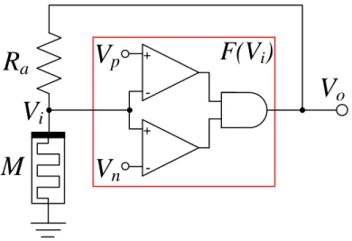
Proposed Circuit: The proposed circuit is based on a voltage divider between a resistor and a memristor, and a feedback function (F(Vi)) as shown in Fig. 1 and Fig. 2. The
voltage on the memristor is given by
Vi(t) =Vo(t)
Rm
Rm+Ra
(2)
The memristor is connected in a polarity such that Rm increases for positive Vi and
de-creases for negative Vi. The threshold voltagesVp and Vn should be selected such that
Vn <0< Vp. A simple implementation ofF(Vi)using two comparators and an AND gate
is shown in Fig. 1, while other implementations are also possible.
Using Fig. 2, the operation of the oscillator can be traced assuming that we start at ‘a’: a→b: At ‘a’ a positive voltage is applied on the memristor sinceVo =Voh. The memristor
resistance will increase, and so willVi until the operating point reaches ‘b’.
b→c: At ‘b’ the value of Vi will just pass Vp, thus Vo will switch to Vol, and the operating
point will jump to ‘c’.
c→d: At ‘c’ a negative voltage is applied on the memristor. The memristor resistance will decrease, and so will|Vi|until the operating point reaches ‘d’.
R
a
M
V
o
V
i
+ -+-V
p
V
n
F(V
i
)
Figure 1: The proposed memristor-based reactance-less oscillator.
d→a: At ‘d’ the value of Vi will just passVn, thus Vo will switch to Voh, and the operating
point will jump to ‘a’.
The circuit will oscillate independent of the initial memristor resistance (Ro). If the initial
point is at (Vi < Vn) the memristor resistance will decrease until reaching ‘d’. If it starts at
(0 < Vi < Vp) the memristor resistance will increase until reaching ‘b’. In both cases, the
circuit will start oscillation from ‘b’ or ‘d’ and will follow the path described previously. The cases (Vn < Vi < 0) and (Vi > Vp) will not happen since Vi andVo must have the same
polarity.
Oscillation Condition:Based on (2), there is a single equivalent memristor resistance for a
V
oV
pV
nV
ohV
olV’
pa
b
c
d
V’
nV
igiven value ofVi. The resistances atVi =Vp andVi=Vnare given by Rmp=Ra Vp Voh−Vp , Rmn=Ra Vn Vol−Vn (3)
Rmp and Rmn have to be selected such that Ron < Rmn < Rmp < Rof f. Based on
the circuit tracing given in the previous section, the oscillation will occur if Vp and Vn are
selected such that
Vp−Vn
Voh
Vol
>0 (4)
Oscillation Frequency: The time required by the circuit to change its state from ‘a’ to ‘b’ is determined by the time required for the memristor to change its resistance fromRmn to
Rmp. The derivative of (1) with respect to time is given by
RmdRm=k0Vi(t)dt (5)
By substituting (2) into (5) then integrating, the equation can be written as
ˆ TH 0 dt= 1 k0Voh ˆ Rmp Rmn (Rm+Ra)dRm (6)
By solving the integration, the time of the positive half cycle is
TH =
Rmp2 −R2mn+ 2Ra(Rmp−Rmn)
2k0Voh
(7)
Similarly, the time of the negative half cycle is
TL=
R2mn−R2mp+ 2Ra(Rmn−Rmp)
2k0Vol
(8)
The duty cycle expression can be derived in a simple form by substituting (3) into (7) and (8)
D= |Vol| Voh−Vol
(9)
by fo = 2Dk0Voh(Voh−Vp)2(Vn−Vol)2 R2 a(VpVol−VnVoh) (2VohVol−VolVp−VohVn) (10)
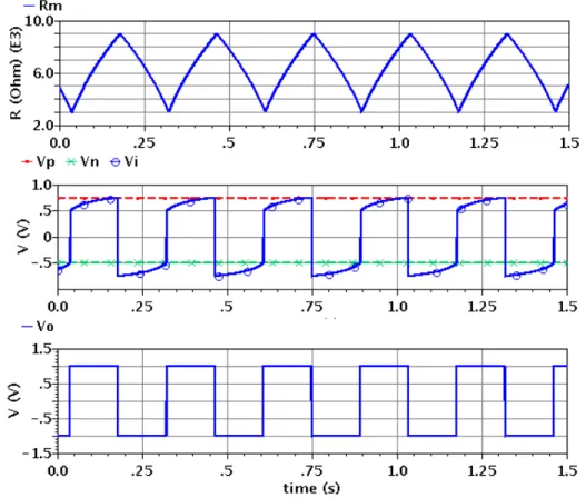
Circuit Simulation: As the access to the experimental realization of memristor is very limi-ted, researchers resort to SPICE and behavioral models of HP memristor [9], or emulate the memristor model using active circuitry [3]. The proposed oscillator was simulated using both SPICE and Verilog-A models, both giving similar results. We choseRon,Rof f,d, and
µvto be 100Ω, 38kΩ, 10nm, and10−10cm2s−1V−1respectively. Fig. 3 shows the transient
simulation results. The memristor resistance oscillates betweenRmn andRmp, which
de-fines the location of the operating points. By substituting the circuit parameters into (3) and (10): Rmn = 3kΩ,Rmp = 9kΩ, and fo = 3.51Hz, which shows excellent match to
the simulation results. For further verification of the mathematical analysis presented, the oscillation frequency was tuned by sweepingRa from2kΩto12kΩ. The maximum error
was 2.13% and 0.1% for SPICE and Verilog-A simulations respectively.
Figure 3: Transient simulation results forRm (upper),Vi (middle), andVo(lower), forRa=
Conclusion: A memristor-based oscillator without using any capacitors or inductors was presented. The introduced reactance-less oscillator enables an area efficient implemen-tation for low frequency oscillators, which find applications in biomedical and embedded systems. Mathematical analysis for the new oscillator is presented and verified using cir-cuit simulation.
References
[1] Chua L. Memristor-The missing circuit element. IEEE Transactions on Circuit Theory. 1971;18(5):507–519.
[2] Strukov DB, Snider GS, Stewart DR. The missing memristor found. Nature. 2008;435:80–83.
[3] Pershin YV, Di Ventra M. Memristive circuits simulate memcapacitors and meminduc-tors. Electronics Letters. 2010 1;46(7):517 –518.
[4] Witrisal K. Memristor-based stored-reference receiver - the UWB solution? Electronics Letters. 2009 2;45(14):713 –714.
[5] Talukdar A, Radwan AG, Salama KN. Generalized model for Memristor-based Wien family oscillators. Microelectronics Journal. 2011;42(9):1032 – 1038.
[6] Radwan AG, Zidan MA, Salama KN. HP memristor mathematical model for periodic signals and DC. In: IEEE International Midwest Symposium on Circuits and Systems (MWSCAS’10); 2010. p. 861–864.
[7] Elwakil AS, Ozoguz S. A low frequency oscillator structure. In: European Conference on Circuit Theory and Design (ECCTD’09); 2009. p. 588 –590.
[8] Hwang C, Bibyk S, Ismail M, Lohiser B. A very low frequency, micropower, low vol-tage CMOS oscillator for noncardiac pacemakers. IEEE Transactions on Circuits and Systems I: Fundamental Theory and Applications. 1995;42(11):962–966.
[9] Biolek Z, Biolek D, Biolkova V. SPICE Model of Memristor with Nonlinear Dopant Drift. Radioengineering. 2009;18(2):210–214.
Authors’ affiliations:
M. Affan Zidan, Hesham Omran, A. G. Radwan and K. N. Salama (Electrical Engineering Program, King Abdullah University of Science and Technology (KAUST), Thuwal, 23955-6900, Saudi Arabia)