CALIFORNIA POLYTECHNIC STATE UNIVERSITY
SAN LUIS OBISPO
SENIOR DESIGN PROJECT
MECHANICAL ENGINEERING DEPARTMENT
Final Design Review
RSVP Spaceship!
Authors: Sponsor:
Taylor Chavez Dr. Barata, Cal Poly Music Department Deven Frauenhofer
Andrew Nott Faculty Advisor:
Zoe Riesen Sarah Harding
i
Statement of Disclaimer
ii
Executive Summary
This document outlines the Final Design Review of a mechanical engineering senior design project at California Polytechnic State University San Luis Obispo. The project was to design and build a spaceship prop that will deploy during the performance put on by the Sound Design program within the Music Department. This performance, RSVP, is in its 25th year. Dr. Antonio G. Barata, the artistic director and producer of RSVP, is sponsoring the project. The key constraints include keeping the prop hidden in a confined space (under a stage that is comprised of multiple 4 ft. by 8 ft. by 3 ft. panels) for the majority of the show, deploying quietly and reliably, and impressing the audience with the climactic reveal and aesthetics of the prop.
This document serves to ensure this project can proceed into manufacturing and demonstration. The final design has been formed and outlined; a final 3D model has been created with engineering drawings to describe major subsystems. Due to recent events with Covid-19, no new construction and testing on the final design has been conducted as of the final project update on March 12th. The Final Design section, Design Verification, and Project Management have been updated up until this point.
iii
Table of Contents
Statement of Disclaimer ... i
Executive Summary ... ii
List of Figures ... v
List of Tables ... vii
1.0 Introduction ... 1
2.0 Background ... 2
2.1 Customer Research ... 2
2.2 Product Research ... 3
2.3 Technical Research ... 3
3.0 Objectives ... 8
3.1 Problem Statement ... 8
3.2 Boundary Diagram ... 8
3.3 Wants/Needs Summary ... 9
3.4 QFD Overview ... 9
4.0 Concept Design ... 11
4.1 Ideation ... 11
4.2 Idea Selection ... 12
4.3 Selected Concept ... 18
4.4 Engineering Assessment ... 22
4.5 Risks and Mitigation ... 22
5.0 Final Design ... 23
5.1 Design Components ... 23
5.2 Structural Prototype... 27
5.3 Proof of Concept ... 27
5.4 Specification Fulfillment ... 28
5.5 Safety, Maintenance, and Repair Considerations... 29
5.6 Cost Analysis... 29
6.0 Manufacturing Plan ... 31
6.1 Procurement ... 31
6.2 Pilot Seat: Materials, Tools, and Operations ... 31
iv
6.4 Rear Hatch (including thruster system): Materials, Tools, and Operations ... 34
6.5 Top Hatch and Hood: Materials, Tools, and Operations... 35
7.0 Design Verification Plan ... 37
7.1 Testing Summary ... 37
7.2 Preliminary Tests... 38
8.0 Shift in Project Scope... 42
9.0 Project Management ... 43
9.1 Design Process ... 43
9.2 Gantt Chart ... 44
10.0 Conclusion ... 45
References ... 46
Attachment A: Sponsor Meeting Notes ... A
Attachment B: Second Sponsor Meeting Notes... B
Attachment C: Third Sponsor Meeting Notes ... C
Attachment D: Engineering Librarian Interview Notes ... D
Attachment E: QFD House of Quality ... E
Attachment F: Sticky Note Ideation ... F
Attachment G: White Board Ideation ... G
Attachment H: Brain Sketching Ideation ... H
Attachment I: Concept Models ... I
Attachment J: Pugh Matrices ... J
Attachment K: Morphological Matrix ... K
Attachment L: Weighted Decision Matrix ... L
Attachment M: Design Hazard Checklist ... M
Attachment N: Indented Bill of Materials ... N
Attachment O: Design Verification Plan ... O
Attachment P: Gantt Chart ... P
Attachment Q: Team Contact Information ... Q
v
List of Figures
Figure 1. Floor plan for RSVP 2019 [1]. ... 2
Figure 2. A painted fiberglass shell with the mold used to create it [7]. ... 4
Figure 3. A robotic arm controlled by a series of hydraulic syringes [12]. ... 6
Figure 4. Various castors [13]. ... 6
Figure 5. A small fogger was used to deliver a plume of smoke from the top of this clock [13]. .. 7
Figure 6. Boundary diagram for the spaceship prop. ... 8
Figure 7. Functional Decomposition... 11
Figure 8. Morphological Matrix. ... 12
Figure 9. Design Idea 1. ... 13
Figure 10. Design Idea 2. ... 13
Figure 11. Design Idea 3. ... 14
Figure 12. Design Idea 4. ... 14
Figure 13. Design Idea 5. ... 15
Figure 14. Design Idea 6. ... 15
Figure 15. Design Idea 7. ... 16
Figure 16. Design Idea 8. ... 16
Figure 17. Weighted Decision Matrix. ... 17
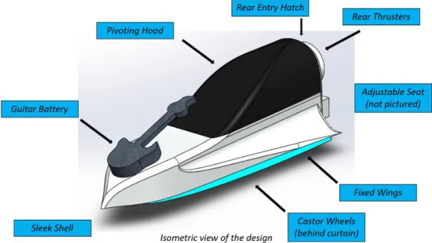
Figure 18. An isometric view of the full prop. ... 18
Figure 19. A side view highlighting the pilot's exit: a pivoting top hatch. ... 19
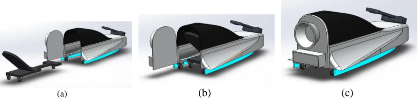
Figure 20. The three stages of the pilot's entrance. He will (a) sit on the rolling seat, (b) roll into the spaceship, and (c) close the rear hatch behind him. ... 19
Figure 21. The spaceship and seat spaced under the stage to allow the pilot an easy entrance. ... 19
Figure 22. The spaceship ready to be deployed from under the stage. ... 20
Figure 23. An isometric view showing that the prop fits under a stage section. ... 20
Figure 24. A concept of what the spaceship might look like as the pilot exits. ... 20
Figure 25. Side view of rolling mechanism for entrance. ... 21
Figure 26. Top view of rolling mechanism for entrance. ... 21
vi
Figure 28. a) The seat fitting within the spaceship, with enough room for the actor. b) The seat
primed for the actor's exit, with foot holes available. ... 24
Figure 29. a) Fuselage with shell and guitar indent. The fog machine is housed under the indent for the guitar. b) Fuselage frame. ... 24
Figure 30. a) Closed top hatch. b) Open top hatch. c) Top hatch frame. d) Thermoplastic shell. 25 Figure 31. The rear hatch, closed and latched with the gate latch. It will be attached to the small lever on the right with a strong string. Once pulled, the actor can roll out on the pilot seat. ... 25
Figure 32. Thruster components. ... 26
Figure 33. a) Closed guitar compartment. b) Open guitar compartment. ... 26
Figure 34. The structural prototype of seat mechanism. ... 27
Figure 35. The fuselage frame. ... 28
Figure 36. The top hatch frame. ... 28
Figure 37. The pilot seat, fuselage, and top hatch assembled together. ... 28
Figure 38. Full proof of concept in the open position, allowing the actor to stand up and step out. ... 28
Figure 39. Cutting an angled 2x4" with miter saw. ... 32
Figure 40. Printed profiles atop MDF sheets. ... 33
Figure 41. Cutting out a piece with a band saw. ... 33
Figure 42. Constructing the frame. ... 34
Figure 43. Both types of chicken wire in a sample shape. ... 38
Figure 44. Unheated thermoplastic sheet with chicken wire mold. ... 39
Figure 45. Heat gun used to shape thermoplastic. ... 39
Figure 46. Both the Mesh Art and TranspArt thermoplastic on the square mesh. ... 40
Figure 47. The Mesh Art thermoplastic laid over the one-inch hex chicken wire... 40
Figure 48. All three layers of wire, cotton batting, and TranspArt. ... 40
vii
List of Tables
Table 1. Foam Material Data for Corafoam and Last-A-Foam. ... 7
Table 2. Specifications Table ... 10
Table 3. Risks and Mitigation Table ... 22
Table 4. Specification fulfillment. ... 29
Table 5. Indented Bill of Materials ... 30
Table 6. Materials and tools required for pilot seat. ... 31
Table 7. Materials and tools required for fuselage. ... 32
Table 8. Materials and tools required for rear hatch. ... 34
Table 9. Materials and tools required for top hatch. ... 35
1
1.0 Introduction
The challenge proposed for our Cal Poly Mechanical Engineering Senior Project Team was to build a spaceship prop for the RSVP production. Our team is composed of four mechanical engineering undergraduate students: Taylor Chavez, Deven Frauenhofer, Andrew Nott, and Zoe Riesen. Our sponsor, Dr. Antonio G. Barata (from the Cal Poly Music Department), is the artistic director. He brought our team in to create this spaceship. As a result of Covid-19, production on the spaceship has been canceled. The project, however, has shifted to creating a theater prop guide based on the work the team has done thus far.
2
2.0 Background
This section outlines the preliminary research performed in three areas: customer needs, existing products, and technical challenges. Customer needs revolve around constraints of the venue, stage, and schedule (due to the performance date). Because this is a creative performance, no products exist that might pose a patent threat, but we will need to be careful about copyright. The technical research gave us insight into actuation, aesthetic shell design, and special effects.
2.1 Customer Research
We interviewed our project sponsor, Dr. Barata, on October 3rd to gain a better understanding of the requirements and logistics for this project. While the complete notes from the interview are in Attachment A, an outline of notable details follows [1].
• There is no traditional backstage, only a side hall.
• The project must adhere to fire safety codes, verified by the stage technicians. • If an electrical device is used, the chief electrician would have to be consulted. • The pilot is about 5’10” and 150 pounds.
• The stage will be comprised of 4 feet by 8 feet panels.
o These panels could be engineered to be 8 feet by 8 feet, more consultation with the stage technicians is needed.
• The stage will be 3 feet tall.
• The spaceship must remain invisible from the audience until deployed.
• There will be an intermission, which may provide an opportunity for the pilot to discreetly enter the spaceship (rather than at the beginning of the play).
• The spaceship will not need to retract back into its housing, it will remain out for the remainder of the play.
• A floor plan for the 2019 RSVP is shown in Figure 1 (this layout will likely be used in the upcoming performance).
3
Subsequent interviews were conducted on October 15th and 28th, outlining more details and logistics about the performance and expectations. While the complete notes from the interview are in Attachments B and C, an outline of notable details follows [1,2].
• Marley floor will be used for the dance floor. Castors must meet to code with Marley floor.
• The stage will be 16 feet by 20 feet.
• Pilot props such as a wig and a space helmet will need to be considered.
• A guitar may be included in the design of the spaceship. Considerations for how have gone into the ideation process.
• For spaceship shape forming, Clint Bryson of the theater department would be a worthwhile consultant.
2.2 Product Research
Although our team made efforts to investigate similar products, our research in this domain proved to be unfruitful—as far as we can tell, no one else has created a realistic spaceship prop such as this. To verify this result, we consulted Cal Poly’s Engineering Librarian, Sarah Lester. Lester confirmed that it is unlikely that products such as this exist. Additionally, Lester verified that it is unlikely this concept is patented. Lester suggested that some model rockets and spaceship movie props might ultimately influence design aspects of our product and to be wary of copyright infringement will be important later in the development of the spaceship [4]. A complete record of notes from this interview is included in Attachment D.
2.3 Technical Research
For technical research relevant to this project, we looked into three areas of interest: aesthetic shell design, actuating mechanisms, and special effects. Because electrical equipment takes a long process to get approved, we focused on methods of actuation that don’t require any electricity.
Shell: Thermoplastics
Thermoplastics are one of the material considerations for the spaceship’s shell. These polymers can be melted and recast when heated to a certain activation temperature. Heating for larger sheets is typically done with an oven, while heating for smaller pieces is typically done with a heat gun. Advantageously, touch ups can be done with a heat gun in the case that part of the shell needs to be redesigned.
4
Finally, Worbla’s “Transpa Art” line could be a consideration if windows are required in the final design. This thermoplastic is translucent and stays active longer than the other thermoplastics. The activation temperature is 250 °F [5].
Shell: Fiberglass
Fiberglass is similar to thermoplastics in that a mold is required to form desired shapes. However, unlike thermoplastics, fiberglass does not have temperature constraints. Layers of cloth-like fiberglass are placed over the mold, then painted with an epoxy glue and left to set. More layers can be added for structural integrity, but this shell is aesthetic: only a few layers are needed.
Fiberglass comes in different weave patterns, thicknesses, and chemical compositions for different use cases. C-glass fiber is the most common, while M-glass is more elastic, and Z-glass can be used if a transparent finish is required [6].
This shell is meant to look futuristic and can mimic the look of carbon fiber. The spaceship will not require the structural capabilities of carbon fiber, so fiberglass is an inexpensive alternative. It can easily be painted to a sleek, glossy finish, as seen in Figure 2 [7].
Figure 2. A painted fiberglass shell with the mold used to create it [7].
Shell: Foam/Wood
Expanded Polystyrene (EPS) foam is commonly used for large-scale props. It is rigid, yet easy to mold. The foam is lightweight, and bonds well with paint, leaving a sleek finish [8]. It would be considerably cheaper than sheet metal, thermoplastics, or fiberglass. Additionally, manufacturing would take less time, because this method does not require a mold.
Supreem foam is used as acoustic padding [9]. It might be necessary to place around certain mechanisms on the spaceship to keep the prop within sonic limitations.
5 Shell: Sheet Metal
Actual cars use shaped metal to create their exteriors, but their process uses industrial machinery perfectly designed to produce that car’s body panels. For the scope of this project, we would use more simple manufacturing methods. The metal could be thin because it needs minimal structural properties, which would make it easier to cut, fold, bend, and curve into the shapes we need.
This option has the most authentic spaceship/sports car look, but would also be expensive, relatively hard to manufacture, and relatively heavy. It might be best to use it sparingly for key aspects of the prop, such as a nose cone, wingtips, or the hatch. It would add a flashy sheen that is hard to get with other materials [10].
Hinges
Hinges would allow a degree of movement for our mechanisms, most likely a door or hatch. Butt hinges are the most commonly used types of hinge. However, some recess would need to be cut into the door for the hinge to properly function.
A flush hinge would remove this space constraint. Contrasting to a butt hinge, a flush hinge has one leaf fit inside the other, allowing for a more compact mechanism. They are lighter and less sturdy; however, this may not be an issue as the door itself will be made of a lighter material [11].
Pneumatic Actuators
Pneumatic actuators rely on compressed air to operate, so space would be required for air tanks, and they would need to be charged before each show. The actuation itself is loud, but in this case, the “Kshhhhhhh” sound could be perfect for opening the door in the climactic reveal.
A quieter alternative that does not rely on electricity is a hydraulic system. Instead of air, a fluid is used to force the motion. Typically, hydraulics are used when a system has large force requirements: 10-25 times larger than pneumatics. While this spaceship does not have that restriction, the silence makes this option worth considering.
6
Figure 3. A robotic arm controlled by a series of hydraulic syringes [12].
Theatrical Effects
Various techniques in prop design are employed regularly to perform ‘magic’ on stage. Some categories of techniques that are relevant include prop motion and smoke effects (assuming lighting and sound will be aptly addressed by Dr. Barata’s RSVP team). Within the motion category, some mechanisms to consider using are castors (as shown in Figure 4), hinges, and pneumatic actuators, and within the smoke effects category, we might consider employing foggers, powder puffs, or dry ice [13].
Figure 4. Various castors [13].
Castors are small wheels that can be mounted to the base of the prop. They can be made from different materials to have different effects—we might consider the rubber castor, as it is quiet compared to some of the other alternatives. A castor can provide linear or ‘swivel’ motion depending on the castor type. Additionally, some castors have a locking feature which will likely be useful to hold the prop in place after deployment.
7
can be placed directly where the effect is needed (as shown in Figure 5) and, if the correct fogger is selected, it can be controlled remotely. This option is reliable for a relatively low cost.
Figure 5. A small fogger was used to deliver a plume of smoke from the top of this clock [13].
Molds
A mold would be required if thermoplastics, or any equivalent shapeable materials, were used. The following research done evaluates the options and properties of different mold materials.
Softwoods make ideal molds because they are easy to shape. They can be cut, whittled, drilled, and sanded without too much effort. Medium density fiberboard is a good candidate that mixes this manufacturability with a rigid structure that holds its shape during the curing.
High density foam is a commonly used solution. When deciding on foam material, compressive resistance is a primary concern so that the mold holds a constant shape. If thermoplastics are used, the foam must be able to operate past the activation temperature of the thermoplastics, above 195°F for most plastics and up to 250°F. If fiberglass is used, temperature will not be an issue, but a porous material will need a coating to prevent the curing epoxy from impregnating the mold.
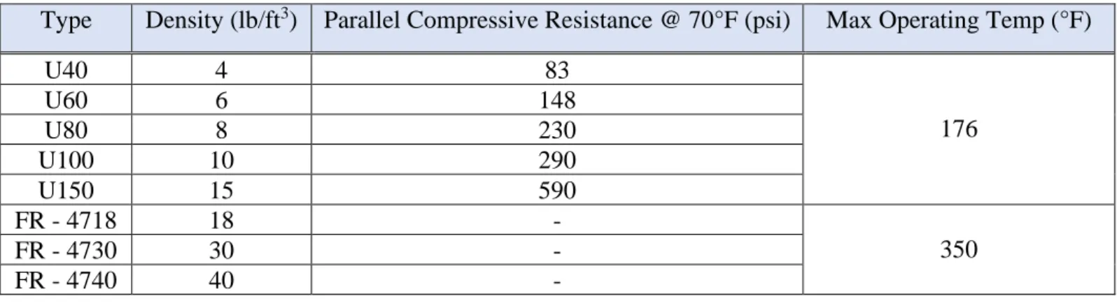
Two foam options have been researched. The Corafoam “U-series" [14] and the Last-A-Foam “FR-4700” series [15]. Relevant data for each series has been provided in Table 1. The Corafoam max operating temperature does not meet the requirements; however, the information on density to compressive resistance could be compared to the density to compressive resistance for the Last-A-Foam.
Table 1. Foam Material Data for Corafoam and Last-A-Foam.
Type Density (lb/ft3) Parallel Compressive Resistance @ 70°F (psi) Max Operating Temp (°F)
U40 4 83
176
U60 6 148
U80 8 230
U100 10 290
U150 15 590
FR - 4718 18 -
350
FR - 4730 30 -
8
3.0 Objectives
This section details the problem we are addressing with this project, the boundaries of the project, the desires of the customer, how we translated these wants into specifications, what these specifications are, and how they will drive the design of our project.
3.1 Problem Statement
Dr. Barata, from the Sound Design Program in the Music Department, coordinates the production of an annual multi-media concert, RSVP. For this year’s production, a rockstar shredder will make his grand return in a sportscar-turned-spaceship. This prop must emerge from a tight space under the stage in a sleek and silent manner to maximize the surprise and awe from the audience. Special effects will reinforce this awe factor. The key is reliability: if this prop snags or fails during one of the five performances, the climax will be ruined. Structurally, the prop must be able to hold an adult male. He must be able to get in while the prop is under the stage, exit in the case of an emergency, and exit the prop elegantly once it has emerged.
3.2 Boundary Diagram
To further describe the scope of our project, our team developed a boundary diagram, as shown in Figure 6. A boundary diagram is a visual tool that shows the boundaries of our product and what external surroundings will influence the design of this product. For our design, the dimensions of the stage as well as the passenger of the spaceship are fixed—both these constraints will influence the design. Although it is not imperative that the spaceship sits on the stage following deployment, it is critical that it can fit under the stage, and thus, our design cannot exceed a maximum height of 30 inches. It should be noted that while standard panels for stage assembly are eight feet by four feet, we have the opportunity to design custom panels allowing for a wider range in dimensions for our spaceship—this is why the boundary in our diagram encompasses part of the stage.
9 3.3 Wants/Needs Summary
Following our discussion with Dr. Barata, our team developed a summary of the associated ‘wants’ for this product. First and foremost, the final product must be reliable. It needs to deploy fully and must maintain its reliability for a total of five deployments (two to three performances and during rehearsals). It must deploy silently—and in a timely manner—from a hidden location in order to maximize the surprise and awe from the audience. The spaceship must be hidden throughout the majority of the performance, which requires it to fit comfortably under the stage (3.5 feet by 8 feet by 30 inches). The spaceship must accommodate an adult pilot with an approximate height of 5’ 10” and approximate weight of 150 lbs. The pilot must be able to enter and exit the spaceship with ease in order to maximize the quietness and speed of deployment, as well as allowing for a quick exit in the case of an emergency.
The aesthetics of the final product are very important. It should look like a sleek spaceship from an old sci-fi movie with design elements from sports cars. It should also include some special effects to increase the “Wow!” factor such as smoke and lights. Ultimately, it must meet any safety requirements for use in the production. And lastly, it must be manufacturable so that it can be built within the timeframe and budget available.
3.4 QFD Overview
Each want and need is weighted for each customer under consideration. Dr. Barata carries the most weight, as he is the primary customer. However, we are also considering the audience, actors/stage technicians, and manufacturers as secondary users. After weighing these needs for each user in a House of Quality chart, we designed measurable specifications for testing each need on the final product. The chart helped us to develop a specification for every need. Additionally, it helped us to realize when a need was more of a design constraint than a testable objective. The full chart can be seen in Attachment E of the appendix.
The House of Quality boiled the customers’ desires down to 13 needs, two of which— looking like a spaceship, and looking like a sports car – we decided to keep as design constraints instead of full specifications. Each specification was designed to ensure a need will be met. These are included in Table 2.
10
Table 2. Specifications Table
Spec # Description Requirement Tolerance Risk Compliance
1 External length 16 ft Max. M I
2 External width 42 in Max. H I
3 External height 32.5 in Max. H I
4 Internal dimensions 5’10”x2’x1’ Min. M I
5 Minimal seat deflection 1in for 150 lb load Max. L T
6 Deployment decibel sound 40 dB Max. M T
7 Mechanism deployment time 60 s Max. L T
8 Initial deployment time 45 s Max. L T
9 Emergency egress 40 s Max. H T
10 Does not snag on stage Pass/Fail N/A H I
11 Smooth surface finish Pass/Fail N/A M I
12 Minimal roof deflection 1in for 20 lb load Max. M T, A H = high, M = medium, L = low; T = test, A = analysis, I = inspection
Specification Description List
1. We will push the prop under one of the available stage sections (4’x8’x3’ without legs). a. The spaceship can fit under multiple panels, allowing for a longer length
2. We will push the prop under one of the available stage sections (4’x8’x3’ without legs). 3. The prop must fit under the stage sections (4’x8’x3’ without legs).
4. Once the internal structure is complete, we will ask the pilot to get in.
5. After placing the prop on a flat surface, we will hold a ruler up to the base and load it. 6. We will collect data from 5 feet away with a phone app that can record decibel levels. 7. A timer will be set during the release of the deploying mechanisms.
8. We will set a timer before initiating the deployment sequence, ending it upon pilot exit. 9. We will set a timer and tell the pilot to get out of the prop while under the stage.
10.We will test by pushing our full assembly out from under the stage in the theater. 11.Formed thermoplastic will be visually inspected for noticeable surface roughness. 12.Incrementally increase load on formed thermoplastic to assess deflection.
High Risk Specifications
11
4.0 Concept Design
This section details the concept development process that led to the formation of our selected design choices. Concept development consists of an ideation phase where we broke down every function to the spaceship and produced relevant concept models. In the idea selection phase, we narrowed down our design choices to a chosen design. Preliminary and risk analysis has begun to show the design will meet specification and safety standards.
4.1 Ideation
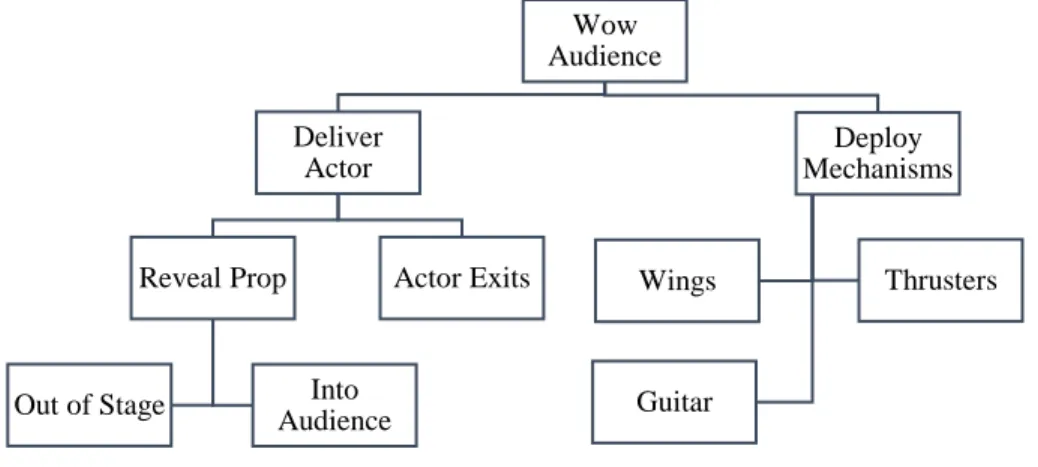
Our team began the ideation process with functional decomposition. We chose our overarching function to be “Wow Audience.” This effectively means that the prop needs to impress the audience with a dramatic entrance, look, and pilot reveal. We then further divided the functions, as shown in Figure 7.
Figure 7. Functional Decomposition.
We verified our functional decomposition methodology through collaboration with other members of our senior project class. Our team then began to ideate by function.
The first method we used was sticky note ideation for how the actor exits. We allowed ourselves 15 minutes to write as many ideas as possible onto sticky notes. A complete list of concepts developed during this ideation session can be found in Attachment F.
In the next ideation session, we used the white boards to ideate on other functions including wings, thrusters, guitar, and lights. We spent about half an hour sketching designs and writing ideas for each of these on the whiteboards. Additionally, we sought feedback and ideas from five random students in our near vicinity. Images formed during this ideation session can be found in Attachment G.
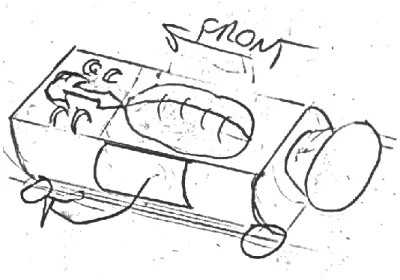
Then, we focused our efforts on the design of the body of the spacecraft. We each sketched our vision of the aesthetics of the spaceship for about five minutes. After the allotted time had
Wow Audience Deliver Actor Reveal Prop Into Audience Out of Stage
12
passed, we gave our sketches to another team member who modified our initial design for five minutes. By the end of the process, each team member had contributed to four different sketches. Images from this brain sketching session can be found in Attachment H.
Following these ideation sessions, we received input from Dr. Barata on some of the preliminary work we had done. Barata directed us to pursue a design that very clearly represents a spaceship, but subtly ties in sportscar elements—especially in the body design. He stated that his vision of this spaceship has very smooth curves, much like a Corvette [3].
To complete our ideation process, we each constructed about five concept models each out of Legos, K’NEX, foam core board, Play-Doh, and other craft material. Images from this prototype session can be found in Attachment I.
4.2 Idea Selection
After generating over one hundred ideas, our team needed a way to narrow down our choices. We had somewhat narrowed down our ideas after testing for feasibility when creating our concept models. We then used a Pugh matrix to rate our top five to ten ideas for each function. The Pugh matrix imposes a ranking scheme by which each concept is rated better, worse, or the same as a datum concept for an array of specifications. The five Pugh matrices we developed are included in Attachment J.
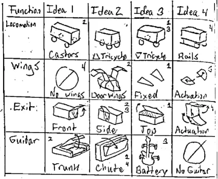
Once we had narrowed down our ideas by function, we developed a morphological matrix. The morphological matrix allows for the combination of ideas from each function into an overarching design. Our morphological matrix is in Figure 8. The top design ideas derived from this matrix are presented in the Figures 9-16.
13
The design presented in Figure 9 focused on a sleek, fixed-wing shell with a compartment in the rear for a guitar. It has minimal contraptions, with minimal movement on both the guitar compartment and hood hatch. Its simplicity, unlikeliness to snag on the stage, and shell design are the biggest benefits. The problems include no method of pilot entry, likely an awkward exit, and very few showy aspects such as expanding wings or a visible guitar.
Figure 9. Design Idea 1.
The space we are designing to (3’x4’x16’) is the biggest constraint in this project, and this tubular design, shown in Figure 10, maximizes use of these dimensions. It includes a trunk, doors that open like the space shuttle, and castors rolling it out. Ideally, the prop needs to look more like a spaceship than a rocket ship, and the highly visible castors will take away from both illusions.
Figure 10. Design Idea 2.
14
pilot could enter from the side as well while the prop is still under the stage. The main drawback to this design is that creating actuating wings takes up valuable height space, which we need to maximize just to fit the actor himself.
Figure 11. Design Idea 3.
The design in Figure 12 is all about creating a grand entrance. During the exiting process, the capsule containing the actor is first raised upright, so that the actor is in a standing position toward the front of the craft. Then, the see-through hatch lifts up to reveal the actor, who is then free to descend down a ramp to the stage. While this design creates an impressive effect, it is lacking when it comes to safety, manufacturability, and speed.
Figure 12. Design Idea 4.
15
front, giving the illusion that it is powering the vehicle. A large thruster is positioned in the back to convey some spaceship like quality.
Figure 13. Design Idea 5.
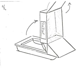
The design in Figure 14 takes inspiration from the DeLorean from Back to the Future while having a unique overall shape. On the sides, the doors pivot upward, and at the rear, there is a car like trunk with thrusters on either side.
Figure 14. Design Idea 6.
16
Figure 15. Design Idea 7.
The design shown in Figure 16 fits under the stage with its wings folded up and in half. The actor enters feet-first through the large rear thruster. After rolling out from underneath the stage, the wings are unfolded to their maximum size for the reveal. Then, the wings fold up and the top hatch pivots forward to allow the actor to exit.
Figure 16. Design Idea 8.
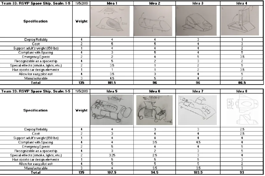
The different combinations from the morphological matrix were then placed in a weighted decision matrix and ranked by adherence to our aforementioned specifications, which can be seen in Figure 17. From our decision matrix, we were able to select our final design, which is discussed in detail in section 4.3.
17
18 4.3 Selected Concept
The weighted decision matrix showed that Idea 5 had the best mix of functions: a guitar battery, no wings, large rear thruster, castor wheels, a domed window, and a side pilot exit. Upon reflection, our team realized three other aspects were worth pursuing from Idea 1: the sleek shell design, fixed wings, and the alternative exit of a pivoting hood mechanism.
We altered Idea 5 because, without the fixed wings and sleek shell, the prop looked more like a car than a spaceship. It is more important that the audience understands that the prop is a spaceship – any resemblance to a sportscar is a bonus that reinforces the rock star aspect, and the guitar being front and center already captured that motif.
A major paradigm shift occurred at this point of the design: we realized that the spaceship does not actually need to support the weight of the actor. So long as the audience is convinced of the fact that the pilot is in the spaceship, the support for the pilot and the actual spaceship itself can be two separate components. As such, we will be implementing a rear door to allow the pilot to enter underneath the stage. This realization, along with the results of our weighted decision matrix lead to our final design concept, as demonstrated in our computer-aided design (CAD) models and our concept prototype.
Computer-Aided Design
With all this decided, we modelled the spaceship with CAD to check dimensions. This made sure the prop could fit under the stage, the actor could enter it, the actor could fit in it, the actor could exit it, the guitar could fit on the hood, and that we could make it look adequately like a spaceship within the space constraint. Each of these functions and dimensional proofs is shown in the Figures 18-24.
19
(a) (b)
Figure 19. A side view highlighting the pilot's exit: a pivoting top hatch.
(a) (b) (c)
Figure 20. The three stages of the pilot's entrance. He will (a) sit on the rolling seat, (b) roll into the spaceship, and (c) close the rear hatch behind him.
Figure 21. The spaceship and seat spaced under the stage to allow the pilot an easy entrance.
20
Figure 22. The spaceship ready to be deployed from under the stage.
Figure 23. An isometric view showing that the prop fits under a stage section.
21 Concept Prototype
Both Figures 23 and 24 represent the design for a rolling mechanism that will allow the pilot to roll into the spaceship. The pilot can lie back, allowing him to fit under the stage, and manually be pushed into the housing of the ship. From there, both the pilot and the ship can be rolled out together. This design allows for the removal of the ship’s floor. This will both give more flexibility with a height constraint as well as eliminate a load issue presented with the pilot standing up on the floor. Holes are cut into the mechanism to easily allow the pilot to stand naturally and elegantly.
This prototype is made simply from a lawn chair mounted on a hardwood dolly with four swivel castors. A simple prototype such as this could actually be used as the final model, because it will never be seen by the audience during the show. However, plans have been devised to build a more sleek, compact design out of wood and castor wheels rated for Marley floor.
Figure 25. Side view of rolling mechanism for entrance.
22 4.4 Engineering Assessment
We wanted to ensure that our concept for a pilot seat would be feasible structurally. To verify this, we prototyped the rolling chair design, as discussed in Section 4.3. A pass-fail test was performed on the design: a team member placed their full weight on the chair. The chair felt stable, did not have visible deflection, and allowed us to roll him around without him falling out.
Additional tests were planned for foam molding and thermoplastic shaping but deemed secondary in importance to the pilot seat test. Because of this, we decided to conduct them between the Preliminary Design Review and the Critical Design Review. They are discussed in detail in Section 5.1.
4.5 Risks and Mitigation
As with any design, it is critical to explore potential risks, so as to avoid them as we continue through the design process. We discussed the risks associated with our chosen design and developed plans to mitigate them. Following our discussion, we completed a design hazard checklist, shown in Attachment M. A summary of our risks and mitigation techniques is found in Table 3.
Table 3. Risks and Mitigation Table
Anticipated Risk Mitigation Technique
Pinch points when opening door Padding around pinch points and testing/rehearsal to verify safety
Pilot must get into/out of vessel, which may require an exertion of physical force
Designing an effective chair mechanism for ease of entrance/exit
Pilot will stay in a confined space for an extended period of time
23
5.0 Final Design
In this section, we detail every subassembly in the design, review the structural prototype built, and describe how the design fulfills our specifications. After this, we clearly state our plan for safety, maintenance and repair, as well as a summary of our anticipated budget.
5.1 Design Components
Now that the CAD has been completed, this section details the functionality of each subsystem in depth. The prop has two separate rolling parts: the pilot seat and the spaceship itself. The spaceship is comprised of a fuselage, top hatch, rear hatch, thrusters, and guitar compartment (Figure 27). The fuselage is the main structure/body of the ship, while every other subsystem is a mechanism that attaches to it. Together, they will allow the pilot to enter the spaceship under the stage, exit dramatically in front of the audience, reveal the guitar, and start playing it. Detailed manufacturing drawings can be found in Appendix R.
Figure 27. The entire spaceship prop, with top hatch and guitar compartment open.
Pilot Seat
24
(a) (b)
Figure 28. a) The seat fitting within the spaceship, with enough room for the actor. b) The seat primed for the actor's exit, with foot holes available.
Fuselage
The fuselage’s frame is the main structural component of the spaceship. Every other subsystem besides the pilot seat attaches to it. It leaves room for the pilot seat to roll into the center, as well as housing the guitar case, guitar, and fog machine in the nose cone (Figure 29 a). The frame has a series of curved wing supports that wire mesh can be stapled to, creating a mold for the spaceship’s aesthetic thermoplastic hull. The entire frame is made from 1x1 inch square wooden dowels, quarter inch MDF, and brackets (Figure 29 b).
(a) (b)
Figure 29. a) Fuselage with shell and guitar indent. The fog machine is housed under the indent for the guitar. b) Fuselage frame.
Top Hatch
25 (a)
(b)
(c) (d)
Figure 30. a) Closed top hatch. b) Open top hatch. c) Top hatch frame. d) Thermoplastic shell.
Rear Hatch
Besides allowing the actor to enter the prop, this hatch must lock in place behind the actor and allow emergency egress in the case of an emergency. It hinges outward to allow the pilot in. It locks in place with a standard gate latch, which can be pulled from a lever within easy reach of the pilot while inside the prop (Figure 31).
26 Thruster
The thrusters on the back of the ship jettison fog. This comes from the fog machine in the nose cone, travels through flexible tubing contained within a PVC pipe, and connects to the holes on the rear hatch. Because the tubing is flexible, it will swing with the rear hatch when it opens.
Figure 32. Thruster components.
Guitar Compartment
To allow for a dramatic reveal, the guitar will be hidden under the “hood of the car.” It will be housed in an actual guitar case, cut to fit within the prop, to ensure it is not damaged. When closed, the hood will look like part of the spaceship hull (Figure 32 a). However, when the latch is undone, it will pivot upwards on two gas springs. The thermoplastic hood will be made structural with metal strips, and the framing of the prop will be hidden by a sheet of wood covered with the same fabric that is within the guitar case (Figure 32 b).
(a)
(b)
27 5.2 Structural Prototype
A structural prototype of the rolling mechanism was manufactured and assembled for CDR. The mechanism was constructed with 2 by 2 in. beams, 2 by 4 in. beams, and MDF board. It can be seen in Figure 33 The objective of this prototype was to test the adjustable chair and verify that the rider will not exceed the specified height. To assist in verification, a “box” with the dimensions to simulate the RSVP stage panel was constructed for the rolling mechanism to move under. This structural prototype is likely to continue to the final design if it successfully meets specifications.
Figure 34. The structural prototype of seat mechanism.
5.3 Proof of Concept
The first step in building the verification prototype was the frame. Our goal was to finish this by the end of Winter quarter, ready for display at the manufacturing and test review. We accomplished this, and with a completed frame and pilot seat, the verification prototype was 40% done. Unfortunately, COVID-19 hit immediately after this and the project construction ceased.
28
Figure 35. The fuselage frame. Figure 36. The top hatch frame.
Figure 37. The pilot seat, fuselage, and top hatch assembled together.
Figure 38. Full proof of concept in the open position, allowing the actor to stand up and
step out.
5.4 Specification Fulfillment
All geometric constraints are met by the final design. We built and tested the pilot seat as our structural prototype, and it did not deflect one inch under an adult male sitting on it. This design minimizes decibel levels by 1) using rubber-edged castor wheels meant to avoid squeaking 2) using wood for the majority of our construction, avoiding metallic clanks and squeaks if any mechanisms rub while in motion, and 3) using gas struts instead of piston cylinders, which would have had a loud hiss upon any use, and potential leakage. The gas springs deploy within seconds, and the castor wheels allow the spaceship and pilot seat to be rolled out in under 30 seconds.
29
roof deflection is minimized by the metal hoops attached to the wooden base of the top hatch. These results are summed up in Table 4.
Table 4. Specification fulfillment.
Spec # Description Requirement Fulfillment
1 External length 16 ft 8.5 ft
2 External width 42 in 38 in
3 External height 32.5 in 32 in
4 Internal dimensions 5’10”x2’x1’ 6’x2’x1’
5 Minimal seat deflection 1in for 150 lb load Structural Prototype Test 6 Deployment decibel sound 40 dB Non-squeak castor wheels
7 Mechanism deployment time 60 s Gas springs
8 Initial deployment time 45 s 30s
9 Emergency egress 40 s Gate latch + accessible lever
10 Does not snag on stage Pass/Fail Smooth outer shell 11 Smooth surface finish Pass/Fail Wood and metal framing 12 Minimal roof deflection 1in for 20 lb load Metal framing
5.5 Safety, Maintenance, and Repair Considerations
Because this prop will only be used for a few performances, maintenance is not a concern. The main components that we anticipate getting damaged are the thermoplastic shell and a part of the frame breaking if someone falls onto it. We chose thermoplastic because it is a forgiving material; if it becomes dented, we can remove it, place it on a mold, heat it up, and the dent will be gone. We made our frame out of wood partially because, if it does break accidentally, it will be easy to unscrew the piece in question, cut a new one, and replace it.
We have complied with every safety guideline required by the theater, such as having no high-power electrical equipment or other fire hazards. As previously discussed, the actor’s safety is a priority, and has been accounted for with the use of a quick release gate latch.
5.6 Cost Analysis
30
31
6.0 Manufacturing Plan
This section focuses on the manufacturing and assembly of our final design. We have broken this section into several subsections including a brief discussion on material procurement, and a manufacture plan for each of the main subsystems: the fuselage, the pilot seat, the rear hatch, and the top hatch. No outsourcing is required for our design. Additionally, it should be noted that the Top Hatch, Rear Hatch, and the Hood were not constructed due to the COVID-19 pandemic.
6.1 Procurement
The majority of materials required for the structural components of our design can be purchased at a home improvement store, such as Home Depot. We plan to source all of our wood, MDF, aluminum, chicken wire, brackets, fasteners, padding, and PVC from this vendor. We plan on getting the castors, hinges, window tint, and gas struts from Amazon. The thermoplastics will be acquired through Worbla, a brand specializing in crafts and cosplay materials. They sell bulk thermoplastic with no shipping cost taking less than a week to arrive. As for the remaining materials, the cotton batting, flexible PVC, and guitar case will be acquired from the online vendors: Joann, Pool Web, and Schecter Guitars, respectively.
6.2 Pilot Seat: Materials, Tools, and Operations
The pilot seat has already been manufactured (see section 5.2). Table 6 shows the materials and tools required for this subsystem and the operations performed are listed below. Operation 3 can be seen in Figure 39.
Table 6. Materials and tools required for pilot seat.
Materials Tools
2x4” Wood Table Saw
2x2” Wood Miter Saw
¼” MDF Staple Gun
Padding Cordless Drill
Castors T-square
Brackets Compass
Spring Loaded Hinges 3/8” Wood Dowel
Fasteners Wood Glue
Operations:
1. Use a T-square and compass to draw out the profile of the backrest on the MDF. 2. Cut out the larger pieces of MDF with a table saw.
32
4. Put frame together with 2x4” and 2x2” pieces and attach bottom MDF pieces to frame with wood screws.
5. Attach angled 2x4” pieces to MDF with wood screws. 6. Attach MDF rails to bottom plate using L-brackets. 7. Attach backrest to bottom plate with hinges.
8. Attach backrest strut attachment points to the backrest with L-brackets. 9. Put together strut rod and back rest strut with wood glue.
10.Attach caster wheel plates with a cordless drill and push on the castor wheels by hand. 11.Attach padding with staple gun.
Figure 39. Cutting an angled 2x4" with miter saw.
6.3 Fuselage: Materials, Tools, and Operations
The majority of the fuselage has been completed. The main part of the frame, which surrounds the pilot, is done, while the front portion where the guitar goes hasn’t been built. Table 7 shows the materials and tools required for this subsystem and the operations to be performed are listed below.
Table 7. Materials and tools required for fuselage.
Materials Tools
Thermoplastic Tin Snips
Chicken Wire Pliers
1x1” Dowel Heat Gun
¼” MDF Miter Saw
Fasteners/adhesives Band Saw 3/8” Wooden Dowel Staple Gun
Hinges Cordless Drill
Padding Utility Knife
33 Operations:
1. Print profiles of the curved MDF base plates and tape onto MDF. 2. Cut out rectangles surrounding the profiles with a table saw. 3. Cut the curves with a band saw.
4. Cut the wood dowel (beams) to length with the miter saw.
5. Assemble frame with a cordless drill and fasteners, and wood glue.
6. Cut chicken wire with tin snips and shape by hand with gloves or with pliers, secure with staples or by bending it around the frame.
7. Lay-up thermoplastics/use heat gun to form. 8. Secure padding with a staple gun.
9. Cut out inner padded portion of guitar case with a utility knife. 10.Secure to the front of the fuselage with staples/fasteners.
Figure 40. Printed profiles atop MDF sheets.
Figure 40 shows the profiles organized on top of the MDF. We went through two rolls of double-sided tape to adhere the profiles to the MDF!
34
This method of creating the small MDF pieces with complex geometry (curves, small internal crevices, etc.) turned out to be a time-consuming task. Each one of the pieces required a printed profile which had to be printed, cut-out, and taped. Then, each piece had to be cut out with a band saw with care so that the resulting MDF piece was just larger than the printed profile, as shown in Figure 41. Finally, each piece was sanded using a variety of methods such as hand, belt, disc, and rotary sanding. After going through these many steps for each piece, it seems very likely that the laser cutter would have been a much faster and more precise option for just about every piece that would in it.
Figure 42. Constructing the frame.
All the mating surfaces of the frame were glued; we then used screws to hold it together while the glue dried, as shown in Figure 42. We only screwed into the square dowel, whereas the MDF pieces were held in place by clamping force from the dowels.
6.4 Rear Hatch (including thruster system): Materials, Tools, and Operations
Some of the manufacturing for the rear hatch will happen at the same time as manufacturing for the fuselage. All manufacturing and assembly of this component should be complete by the end of April. Table 8 shows the materials and tools required for this subsystem and the operations to be performed are listed below.
Table 8. Materials and tools required for rear hatch.
Materials Tools
¼” MDF Table Saw
Hinges Utility Knife
4” Barrel Bolt in Zinc Plate Wood Glue Fog Machine Cordless Drill 2” Flexible Tubing
35 Operations:
1. Cut out panels for the square thruster with a table saw.
2. Cut out conical section of thermoplastic with a utility knife for the circular thruster. 3. Print profile of rear plate and cut with band saw.
4. Adhere thrusters to rear plate with wood glue.
5. Attach spring-loaded hinges with cordless drill and wood screws. 6. Run piping from fog machine to thruster outlet.
6.5 Top Hatch and Hood: Materials, Tools, and Operations
Similar to the rear hatch, some of the manufacturing for the top hatch and the hood will happen at the same time as manufacturing for the fuselage. All manufacturing and assembly of this component should be complete by the end of April. Table 9 shows the materials and tools required for this subsystem and the operations to be performed are listed below.
Table 9. Materials and tools required for top hatch.
Materials Tools
1x1” Wood Miter Saw
¼” MDF Table Saw
Clear thermoplastic Tin Snips
Chicken Wire Pliers
Cotton Batting Heat Gun
Tint Staple Gun
Gas Strut Cordless Drill
L-Bracket Chop Saw
1/8” Aluminum Strips
Operations (Top Hatch):
1. Use the miter saw to cut the 1x1” wood pieces to length. 2. Print the rear arch profile to cut the curved MDF piece. 3. Put together frame with wood screws.
4. Use the band saw to cut out the members of the four-bar linkage. 5. Assemble four-bar linkage with fasteners.
6. Cut aluminum strips to length with a chop saw. 7. Attach aluminum strips to frame with wood screws. 8. Cut the chicken wire to size with tin snips.
9. Use gloves/pliers to mold the chicken wire to shape.
10.Place cotton batting over chicken wire before molding thermoplastic. 11.Melt thermoplastic to mold with heat gun.
36 Operations (Hood):
1. Cut aluminum strips to length with a chop saw. 2. Assemble aluminum frame with fasteners.
3. Cut and shape chicken wire with tin snips and pliers. 4. Shape the thermoplastic with the heat gun.
37
7.0 Design Verification Plan
This section details the Design Verification Plan our team has developed to ensure that our final product is operating according to our design specifications. For this section, our specifications listed in Table 2 was reconsidered and updated. Tests were then developed for each specification, as detailed in this section and in Attachment O. Additionally, preliminary testing has already taken place, and the results of these tests are included in this section. It should be noted that aside from the preliminary tests mentioned, the majority of the tests mentioned were not conducted due to the COVID-19 pandemic.
7.1 Testing Summary
The specifications tabulated in Table 2 generally fall into three different categories: will the prop fit the required dimensions (i.e. will the actor fit in the prop and will the prop fit under the stage), will it effectively deploy, and does it meet minimum aesthetic requirements. The first category includes specification #1 through #5, the second category includes specification #6 through #10, and the final category includes specifications #11 and #12. Specification #1 through #3 seek to verify that all external dimensions are tolerable, while specifications #4 and #5 ensure that the prop can support the weight and size of our actor. Deployment time requirements are given in specifications #7 and #8, and deployment sound is limited in specification #6. Specification #9 sets a standard for emergency egress, and specification #10 ensures that the prop doesn’t catch on the stage during deployment. Specification #11 ensures that the final design has a smooth exterior surface finish and specification #12 ensures that the exterior can withstand some loading and maintain the aforementioned surface finish. An overview of the tests required for each of these specifications is as follows, however, our complete Design Verification Plan can be found in Attachment O.
For the majority of our inspections, we will make use of the stage and our actor, as these are the most accurate sources for measurement in our case. Inspection is required for specification #1 through #3 and will utilize the stage. The prop will be pushed under the stage to verify that the prop clears all sides of the stage at every point during the push back. A similar inspection is required for the internal dimensions (specification #4): verifying that the actor fits in the chair and that the chair fits within the expected dimensions of the ship. This can be done using our structural prototype and cardboard boxes with the approximate ship dimensions. Specification #6 requires a phone application that can record decibels. We will then measure the levels from a set distance away from the prop as it is being deployed.
38
after a timer has started. The timer will be stopped after the actor has fully exited the vessel. The test for specification #10, or the ‘snag test,’ will be performed by pushing our full assembly out from under the stage and performing a visual inspection as to whether or not the prop snags on the curtain of the bottom of the stage.
Test 5: The test for specification #5 will require the actor, or someone of similar weight, our structural prototype (the pilot seat) and a ruler—we will measure the initial height of the chair and then determine the deflection from the pilots weight by taking a secondary measurement. Further analysis will be performed to verify we are within required tolerance.
Test 12: A load test will be performed on the roof of the final assembly to determine the load capacity of the formed thermoplastics (specification #12). A can will be placed on top of the ship and marbles will be added into the can. The deflection of the roof will be measured for each incremental load and analyzed.
Preliminary tests have been performed on thermoplastic samples to assess surface finish (specification #11).
7.2 Preliminary Tests
Our team decided chicken wire was an appropriate and affordable mold for thermoplastic shaping. Two types of chicken wire were considered, a 1-inch hex wire and a ¼-inch square wire as seen in Figure 43. Both sets of wire were tested for ease of bending and shape retain-ability. We found that both sets were relatively easy to bend. The 1-inch hex, however, proved to be unable to hold its shape compared to the ¼-inch square. The square wire proved to be able to fold easily in multiple directions without deforming like the hex.
Figure 43. Both types of chicken wire in a sample shape.
39
harden and ten minutes to completely cool. Afterwards, the thermoplastic was removed from the wire mold with relative ease.
Figure 44. Unheated thermoplastic sheet with chicken wire mold.
Figure 45. Heat gun used to shape thermoplastic.
40
Figure 46. Both the Mesh Art and TranspArt thermoplastic on the square mesh.
Figure 47. The Mesh Art thermoplastic laid over the one-inch hex chicken wire.
In order to decern whether this material could be remolded, the larger piece of Mesh Art used on the hex wire was reheated, smoothed out, and reshaped onto a piece of square wire. We found that most of the bumps from the initial forming were eliminated. Overall, the remold test demonstrated that during manufacturing, it would be simple to touch up the thermoplastic.
Following this test, we considered adding a cotton batting between the mold and thermoplastic in attempt to prevent indentation from the chicken wire in the thermoplastic (this was especially noticeable for the clear thermoplastic). The batting was set up as shown in Figure 48. Trials were conducted for both the Mesh Art and the TrasnpArt.
41
The test showed that the cotton batting made a noticeable difference in indentation for the TranspArt, and less of an impact on the Mesh Art. However, we noticed that the batting hindered the thermoplastic from taking the exact shape of the wire. Figure 49 shows the effects of with and without the batting on the TranspArt.
42
8.0 Shift in Project Scope
The COVID-19 pandemic had a wide-spread impact on everyone around the world. To slow the spread of coronavirus in San Luis Obispo, Cal Poly opted to close campus as of early April and transition Spring Quarter courses to an entirely virtual format. For us, this meant ceasing all manufacturing of our spaceship, as we no longer had access to Cal Poly Machine Shops. Additionally, the RSVP performance was transitioned to a virtual platform, meaning that the show did, in fact, go on! However, this also meant that the Music Department would no longer require a spaceship prop for the performance. Unfortunately, this meant that we did not get to see our spaceship concept come to fruition.
Although we did not get to complete our project in the way that we had intended to, our team is proud of all we have learned through this process and is incredibly grateful for our ability to continue our education remotely during this troubling time. As such, we have decided to ‘finish’ our project by creating an online resource that encompasses all we have learned through this design process. Our hope was that anyone needing to create a prop for any theatrical production might find some relevant information within our guide. As such, we did our best to make our guide as general as possible, while still providing relevant details from our project. We chose to use ‘Instructables’ as our medium for making this guide. Through it, we were able to produce a 25-step process for making a theatrical prop entitled: An Engineer’s Guide to Making a Theatrical
Prop. The Instructables guide can be found using the following link:
43
9.0 Project Management
This section outlines the design process we have taken to complete the project. Our completed major milestones can be found in Table 11. The Gantt chart (Attachment P) summarizes these milestones and tasks in a schedule for the entire project.
9.1 Design Process
Following the Preliminary Design Review, we began procuring materials in order to begin testing. Foam as a mold proved to be a heavily expensive option and, having taken inspiration from design projects such as rose float, found the potential in chicken wire as a more cost-effective solution. Ordering for testing purposes also allowed us to gage the length of lead-time. The thermoplastics were the longest, taking a little less than a week to deliver.
By the Interim Design Review, some of preliminary had been conducted and both the thruster and top hatch pivot mechanisms had been designed. The CAD model at this time had been fleshed out and nearly completed.
Prior to CDR, the structural prototype for the chair mechanism was manufactured and assembled, engineering drawings were created for each subsystem, preliminary tests were performed, and funds through the Baker/Koob Endowment were secured. Additionally, a Manufacturing Plan and a Design Verification page were written for assembly and testing.
Following approval after the CDR, we began ordering materials and complete a Risk Assessment for the Safety Review. As of early March, we were in full swing of manufacturing the confirmation prototype and, on March 12th, the status of which was presented during the Manufacturing and Test Review.
Following the Manufacturing and Test Review, we began the manufacturing and assembly of the confirmation prototype. Before RSVP rehearsals, we planned on testing the confirmation prototype to ensure it meets the required specifications for a successful delivery during the show. However, as of mid-March, the scope of our project changed drastically due to the COVID-19 pandemic.
Due to the nature of this pandemic, large gatherings, such as the RSVP performance, were canceled or postponed. Additionally, Cal Poly courses became completely virtual for Spring Quarter 2020, and students no longer had access to many campus resources, including the Machine Shops. These unfortunate circumstances prompted us to become more creative with the nature of our project.
44
Table 10. Key Deliverable Table
Deliverable Completion Date
Preliminary Design Review November 11th, 2019 Critical Design Review February 4th, 2020 Manufacturing and Test Review March 12th, 2020
Load-in Dates* May 15-17th, 2020
RSVP Performance* May 26th and 28th, 2020 Final Design Review / Expo May 29th, 2020 *No longer applicable, due to the COVID-19 pandemic.
9.2 Gantt Chart
45
10.0 Conclusion
46
References
1. Barata, Antonio. Personal Interview. 3 Oct. 2019.
2. Barata, Antonio. Personal Interview. 15 Oct. 2019.
3. Barata, Antonio. Personal Interview. 28 Oct. 2019.
4. Lester, Sarah. Personal Interview. 15 Oct. 2019.
5. “Worbla Thermoplastics.” Worbla Thermoplastics, https://www.worbla.com/. Accessed 8 Oct. 2019
6. “Fiberglass Types” Polser,https://polser.com/en/frp/fiberglass-types. Accessed 8 Oct. 2019 7. “Exomotive: How to Build a Sports Car” Exomotive,
https://www.youtube.com/watch?v=Y-EckDSKS9s. Accessed 8 Oct. 2019
8. “EPS Theater Set and Prop Design “ InsulationCorp, https://insulationcorp.com/eps-theater-set-and-prop-design/. Accessed 6 Oct. 2019
9. “Types of Foam” FoamOnline, https://foamonline.com/types.php. Accessed 8 Oct. 2019 10. DiY, Muscle Car. “Automotive Bodywork: How to Form, Fit and Smooth
Sheetmetal.” Muscle Car DIY, 3 Apr. 2015,
https://www.musclecardiy.com/bodywork/automotive-bodywork-how-to-form-fit-and-smooth-sheetmetal/.
11. HingeOutlet, https://www.hingeoutlet.com/pages/about-us. Accessed 9 Oct. 2019
12. Bucak Technical and Industrial Vocational High School “Hydraulic System Based Robot Arm” YouTubehttps://www.youtube.com/watch?v=gJ-hhgcyH-Y. Accessed 4 Oct. 2019 13. Hart, Eric. The Prop Effects Guidebook: Lights, Motion, Sound, and Magic. Focal Press,
2018.
14. “CORAFOAM® High Density.” DUNA,
www.dunagroup.com/usa/products/foams/corafoam-high-density.2019
A-1
Attachment A: Sponsor Meeting Notes
• It is critical to understand the space for which we’re designing o the performance will be in the pavilion
▪ this performance space essentially has no backstage (all scene changes/prop deployment need to be creative and discreet)
▪ this space is ideal because it provides much more intimacy between the actors and the audience
• Previous groups have successfully deployed elaborate mechanisms o Turntable
o Kelp bed
• The devil is in the details
o Size constraints: Stage height and panel width (~ 30in by 4ft) o bureaucratic things: theater safety
▪ must pass inspection by theater department
▪ using motors/electricity requires certification by Cal Poly (may be better to stay away from this option)
• Budget
o Seek money where we can
▪ Some money available, but this will be an expensive show!
• note: it is important not to share details of this show as it is a part of the mystique
o Example: there was a scene representing primitive humans in which a hunter comes back with a dead deer. As a sort of publicity stunt, Dr. Barata walked out of his office and down the hall with this dead deer prop in hand--its safe to say some eyebrows were raised.
• Summary of last year’s show
A-2
▪ some of his music was sent into space by NASA
• it turns out aliens got a hold of his music and to them, it’s not music, it’s medicine--it has cured one of the great plagues of their planet
o In the beginning, it’s like the audience is backstage of a talk show watching an interview with this shredder
o At the end, you’re actually watching the interview ▪ the rock star reveals he’s leaving
o The show concludes with a radio saying his plane has gone missing and the audience is left unsure of what happened
• This year’s show
o There is a memorial show for this shredder
o At the near end of the show, he returns on a spaceship!
▪ Dr. Barata must be able to get into the spaceship discreetly and exit following deployment
o this show will be EXPENSIVE
▪ recreate red carpet feel before the show to celebrate the 25th (and perhaps final) year of RSVP
• video, tux, gowns, etc. • Themes:
o Last year: Issues of religion
▪ Shredder (represents Abraham) doesn’t get into the hall of fame (represents promised land)
o This year: call and response style (call from god?) ▪ aliens = angels/people from spiritual realm ▪ want audience response!!
B
Attachment B: Second Sponsor Meeting Notes
• Deploy on the stage or dance floor? o Deploy onto the dance floor area!
▪ Marley floor--material on the dancefloor (similar to the vinyl): 1/4 in rubbery material with the right amount of stick and slide for a dancer ▪ usually need to get verification for castors --talk to people at the PAC ▪ smoother surface for rolling, dampens the sounds (trivially)
• Past materials used?
o No prior examples (N/A: Turntable: wood)
o Thermoplastics sounds good! —run by Clint, may have had prior experience o High density foam too?
• RSVP is comprised of acting, dancing, and musical moments --this show in particular might have more musical moments
• Intermission --will view be obscured ever? o might be a curtain in the back?
o maybe have a hatch on the stage? **This wouldn’t be a difficult task--ask clint • Tinted window… for spaceship
o Audience can't see driver until he gets out! (advantageous if driver can see) • Driver costume:
o maybe space helmet.. otherwise traditional attire o maybe will have a guitar—guitar hatch!!!!
• Budget?
o ~$1000-$2000 from music department o hopefully ~$2000 from CPConnect • Frame?
o Wood? Aluminum?
• Smoker/fogger for thruster (can buy one that is driven in control room) • Transportation to PAC?
o Huge doors
![Figure 2. A painted fiberglass shell with the mold used to create it [7].](https://thumb-us.123doks.com/thumbv2/123dok_us/8219323.2179173/12.918.346.626.487.681/figure-painted-fiberglass-shell-mold-used-create.webp)