Medium Voltage
technical guide
Technical collection
Basics for MV
cubicle design
This guide is a catalogue
of technical know-how
intended for medium voltage
equipment designers.
Goal
b
Present MV products and equipment and their environment.
b
Facilitate their choice, according to a normative system of
reference.
b
Provide design rules used to calculate the dimensions
or characteristics of an MV switchboard.
How?
b
By proposing simple and clear calculation outlines to guide
the designer step by step.
b
By showing actual calculation examples.
b
By providing information on units of measure and international
standards.
b
By comparing some of the main international standards.
In summary
This guide helps you to carry out the calculations required
to define and determine equipment dimensions and provides
useful information enabling you to design your MV switchboard.
Medium Voltage
Medium Voltage
technical guide
General contents
Presentation
5
Design rules
13
Switchgear defi nition
47
Units of measure
71
Standards
75
Medium Voltage
technical guide
Presentation
Prefabricated metal-enclosed switchgear
6
Introduction 6
Voltage 6
Current 8
Frequency 9
Switchgear functions
9
Presentation
Prefabricated metal-enclosed
switchgear
Introduction
In order to design a medium-voltage cubicle, you need to know the following basic magnitudes:
Voltage Current Frequency
Short-circuit power.
The voltage, the rated current and the rated frequency are often known or can easily be defined, but how can we calculate the short-circuit power or the short-circuit current at a given point in an installation?
Knowing the short-circuit power of the network allows us to choose the various parts of a switchboard which must withstand significant temperature rises and electrodynamic constraints. Knowing the voltage (kV) will allow us to define the dielectric withstand of the components. E.g.: circuit breakers, insulators, CT.
Disconnection, control and protection of electrical networks are achieved by using switchgear.
The classification of metal-enclosed switchgear is defined in the IEC standard 62271-200 with a functional approach, using several criteria.
Accessibility to compartments by persons
Level of Loss of Service Continuity when a main circuit compartment is opened
Type of metallic or insulated barriers, between live parts and opened accessible compartment
Level of internal arc withstand in normal operating conditions.
Voltage
Operating voltage U (kV)
It is applied across the equipment terminals.
It is the network voltage where the equipment is fitted.
Rated voltage U
r
(kV)
This is the maximum r ms (root mean square) value of the voltage that the equipment can withstand under normal operating conditions. The rated voltage is always higher than the operating voltage and, is associated with an insulation level.
Insulation level U
d
(kV r ms 1 min) and U
p
(kV peak)
This defines the dielectric withstand of equipment to power frequency overvoltages and lightning impulses.
Ud: overvoltages of internal origin, accompany all changes in the circuit: opening or closing a circuit, breakdown or shorting across an insulator, etc… It is simulated in a laboratory by the rated power-frequency withstand voltage for one minute.
Up: overvoltages of external origin or atmospheric origin occur when lightning falls on or near a line. The voltage wave that results is simulated
b b b b
b b b b
b
b
To start with, here is some key
information on MV switchboards!
reference is made to the International
Electrotechnical Commission (IEC).
Example:
Operating voltage: 20 kV Rated voltage: 24 kV
Power frequency withstand voltage 50 Hz 1 min: 50 kV r ms
Impulse withstand voltage 1.2/50 µs: 125 kV peak. b
b b b
Presentation
Prefabricated metal-enclosed
switchgear
Standards
Apart from special cases, Schneider Electric equipment are compliant with tables 1a and 1b of IEC standard 62271-1 common specifications.
Rated voltage
Rated lightning impulse withstand voltage 1.2/50 µs 50 Hz
Rated
power-frequency withstand voltage
Normal operating voltage
kV r ms kV peak 1 min kV r ms kV r ms
List 1 List 2
7.2 40 60 20 3.3 to 6.6
12 60 75 28 10 to 11
17.5 75 95 38 13.8 to 15
24 95 125 50 20 to 22
36 145 170 70 25.8 to 36
The values of withstand voltages in the tables are considered for normal services conditions at altitudes of less than 1000 metres, 20°C, 11 g/m3
humidity and a pressure of 101.3 kPa.
For other conditions, correction factors are applied for the test and in some cases, derating has to be considered.
Each insulation level corresponds to a distance in air which guarantees equipment withstand without a test certificate.
Rated voltage
Rated impulse
withstand voltage Distance/earth in air cm
kV r ms 1.2/50 µs
7.2 60 10
12 75 12
17.5 95 16
24 125 22
36 170 32
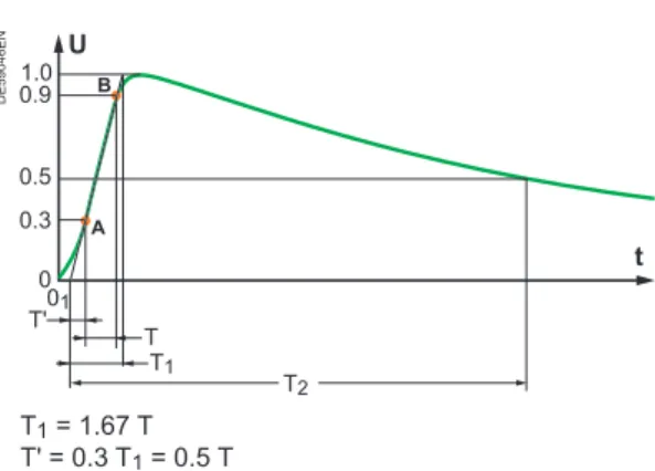
IEC standardised voltages
DE59002EN
Rated lightning withstand voltage
U
t Um
0.5 Um
0 1.2 µs 50 µs
20 28 38 50 70
7.2 12 17.5
24 36
75 60
95 125
170 Rated voltage
Ud Ur Up
Rated power frequency withstand voltage 50 Hz 1 min
Presentation
Prefabricated metal-enclosed
switchgear
Current
Rated normal current: I
r
(A)
This is the r ms value of current that equipment can withstand when permanently closed, without exceeding the temperature rise allowed in standards.
The table below gives the temperature rises authorised by the IEC 62271-1 according to the type of contacts.
Rated normal current:
Type of mechanism of material
Max. values Max. temperature of conductor (°C)
Max. temp. rise = t°. max. – 40°C Contacts in air
Bare copper or copper alloy 75 35
Silver or nickel plated 105 65
Tin-plated 90 50
Bolted connections or equivalent devices in air
Bare copper, bare copper alloy
or aluminium alloy 90 50
Silver or nickel plated 115 75
Tin-plated 105 65
N.B.: rated currents usually used by Schneider Electric are: 400, 630, 1250, 2500 and 3150 A.
Rated short-time withstand current: I
k
(A)
This is the rms value of the current which the switchgear can carry in the closed position during a specified short time. Short time is generally 1 s, and sometimes 3 s.
Rated peak withstand current: I
p
(A)
This is the peak current associated with the first major loop of the rated short-time withstand current which the switchgear can carry in the closed position.
Operating current: I (A)
This is calculated from the consumption of the devices connected to the considered circuit. It is the current that really flows through the equipment. If we do not have the information to calculate it, the customer has to provide us with its value. The operating current can be calculated when we know the power of the current consumers.
Examples:
For a switchboard with a 630 kW motor feeder and a 1250 kVA transformer feeder at 5.5 kV operating voltage.
calculating the operating current of the transformer feeder:
Apparent power: b
v
calculating the operating current of the motor feeder:
cosϕ = power factor = 0.9 η = motor efficiency = 0.9
v
I = = = 82 AP 630 5.5 • 1.732 • 0.9 • 0.9 U3 cosϕη
S = UI3
I = = = 130 AS U3
1250 5.5 • 1.732
Presentation
Prefabricated metal-enclosed
switchgear
Minimal short-circuit current:
I
sc
min (kA r ms) of an electrical installation
(see explanation in “Short-circuit currents” chapter.)
R ms value of maximal short-circuit current:
I
th
(kA r ms 1 s or 3 s) of an electrical installation
(see explanation in “Short-circuit currents” chapter.)
Peak value of maximal short-circuit:
I
dyn
(kA peak) of an electrical installation
(value of the initial peak in the transient period) (see explanation in “Short-circuit currents” chapter.)
Frequency fr (Hz)
Two frequencies are usually used throughout the world: 50 Hz in Europe
60 Hz in America.
Several countries use both frequencies indiscriminately.
Switchgear functions
Designation and symbol
Function Current switching
Operating current
Fault current
Disconnector
Isolates
Earthing disconnector
Connects to the earth (short-circuit making capacity)
Switch
Switches b
Disconnector switch
Switches
Isolates b
Fixed circuit breaker
Switches
Protects b b
Withdrawable circuit breaker Switches Protects
Isolates if withdrawn
b b
Fixed contactor
Switches b
Withdrawable contactor
Switches
Isolates if withdrawn b
Fuse Protects
does not isolate b(once)
b = Yes
b v v
Presentation
Prefabricated metal-enclosed
switchgear
Accessibility and service continuity
Some parts of a switchgear may be made accessible for the user, for various reasons from operation to maintenance, and such an access could impair the overall operation of the switchgear then decreasing the availability.
The IEC 62271-200 proposes user-oriented definitions and classifications intended to describe how a given switchgear can be accessed, and what will be the consequences on the installation.
The manufacturer shall state which are the parts of the switchgear which can be accessed, if any, and how safety is ensured. For that matter, compartments have to be defined, and some of them are going to be said accessible.
Three categories of accessible compartments are proposed:
Interlock based access: the interlocking features of the switchboard ensure that the opening is only possible under safe conditions
Procedure based access: the access is secured by means of, for instance, a padlock and the operator shall apply proper procedures to ensure a safe access
Tool based access: if any tool is needed to open a compartment, the operator shall be aware that no provision is made to ensure a safe opening, and that proper procedures shall be applied. This category is restricted to compartments where no normal operation nor maintenance is specified.
When the accessibility of the various compartments are known, then the consequences of opening a compartment on the operation of the installation can be assessed; it is the idea of Loss of Service Continuity which leads to the LSC classification proposed by the IEC: “category defining the possibility to keep other high-voltage compartments and/or functional units energised when opening a accessible high-voltage compartment”.
If no accessible compartment is provided, then the LSC classification does not apply.
Several categories are defined, according to “the extent to which the switchgear and controlgear are intended to remain operational in case access to a high-voltage compartment is provided”:
If any other functional unit than the one under intervention has to be switched off, then service is partial only: LSC1
If at least one set of busbars can remain live, and all other functional units can stay in service, then service is optimal: LSC2
If within a single functional unit, other(s) compartment(s) than the connection compartment is accessible, then suffix A or B can be used with classification LSC2 to distinguish whether the cables shall be dead or not when accessing this other compartment.
But is there a good reason for requesting access to a given function? That’s a key point.
b b
b
b b b
Presentation
Prefabricated metal-enclosed
switchgear
PE57700
Example 1:
Here is a GIS solution with in (D) what is said to be “Base section with cable connection area” (AREVA WI). There is no connection compartment, and the only HV compartments are gas filled.
Then, there is no accessible compartment to be considered for LSC classification.
LSC is not relevant in that case, and service continuity during normal operation and maintenance is expected to be total.
DE59017
Example 2:
Here is a GIS solution (Schneider Electric CGset) with an air insulated connection (and possibly VT) compartment.
This compartment is accessible (with tools). The other HV compartments are not accessible.
Access to the connection compartment is possible with the busbar(s) live, meaning all other functional units can be kept operating.
The LSC classification applies, and such solution is LSC2.
DE59016
Example 3:
Here is a GIS solution (Schneider Electric GMset) with an air insulated connection (and possibly VT) compartment. This compartment is accessible and interlocked with the earthing function.
The circuit breaker can be extracted (tool access compartment), even if that is not considered as normal operation nor normal maintenance. Access to one functional unit within a switchboard does not require any other functional unit to be switched off. Such solution is LSC2A.
PE57703
Example 4:
A mixed technology (Schneider Electric GenieEvo) with an air insulated connection compartment, and an air insulated main switching device which can be extracted with the busbar live, thanks to the disconnector. Single line diagram is similar to example 2.
If both the connection compartment and the circuit breaker compartment are accessible, and access to any of them means the cables are first switched off and earthed. Category is LSC2A.
DE56780
Example 5:
A very classic structure of withdrawable air-insulated switchgear (Schneider Electric MCset), with interlock accessible compartments for the connections (and CTs) and the main switching device. The withdrawing function provides the independence of the main switching device compartment from the other HV compartments; then, the cables (and of course the busbar) can remain live when accessing the breaker.
The LSC classification applies, and category is LSC2B.
DE59003
Example 6:
A typical secondary distribution switch-disconnector switchgear, with only one interlock accessible compartment for the connection (Schneider Electric SM6).
When accessing one compartment within the switchboard, all other functional units are kept in service. Category is again LSC2. Similar situation occurs with most of the Ring Main Units solutions.
PE57702
Example 7:
An unusual functional unit, available in some ranges: the metering unit which provides VTs and CTs on the busbar of an assembly (here a Schneider Electric RM6). This unit has only one compartment, accessible to possibly change the transformers, or their ratio. When accessing such a compartment, the busbar of the assembly shall be dead, then preventing any service continuity of the assembly. This functional unit is LSC1.
Presentation
Prefabricated metal-enclosed
Medium Voltage
technical guide
Design rules
Short-circuit power
14
Introduction 14
Short-circuit currents
15
Transformer 16
Synchronous generators
17
Asynchronous motor
17
Reminder concerning the calculation of three-phase
short-circuit currents
18
Example of three-phase calculation
20
Busbar calculation
24
Introduction 24
Thermal withstand
27
Electrodynamic withstand
30
Intrinsic resonant frequency
32
Busbar calculation example
33
Dielectric withstand
41
The shape of parts
43
Distance between parts
43
Protection index
44
IP code
44
Design rules
Short-circuit power
Introduction
The short-circuit power depends directly on the network configuration and the impedance of its components: lines, cables, transformers, motors... through which the short-circuit current flows.
It is the maximum power that the network can provide to an installation during a fault, expressed in MVA or in kA r ms for a given operating voltage.
U Operating voltage (kV)
Isc Short-circuit current (kA r ms) Ref: following pages
The short-circuit power can be assimilated to an apparent power. The customer generally imposes the value of short-circuit power because we rarely have the information required to calculate it. Determination of the short-circuit power requires analysis of the power flows feeding the short-circuit in the worst possible case.
Possible sources are:
Network incomer via power transformers. Generator incomer.
Power feedback due to rotary sets (motors, etc); or via MV/LV transformers.
b
b
b
b b b
63 kV 63 kV
T1 A T2
A B C
D1
D6
MV
LV
D4 D5 D7
D2 D3
10 kV
T3 M
LV MV
T4
Isc4 Isc5
Isc1 Isc2 Isc3
Example 1:
25 kA at an operating voltage of 11 kV
Ssc = 3 • U • Isc
DE59004
Zsc
Isc
L A
U Zs R
B E
DE59005EN
We have to calculate each of the Isc currents.
Example 2:
Feedback via LV Isc5 is only possible if the transformer (T4) is powered by another source. Three sources are flowing in the switchboard (T1-A-T2)
circuit breaker D1 (s/c at A) Isc2 + Isc3 + Isc4 + Isc5
circuit breaker D2 (c/c at B) Isc1 + Isc3 + Isc4 + Isc5
circuit breaker D3 (c/c at C) Isc1 + Isc2 + Isc4 + Isc5 b
b v v v
Design rules
Short-circuit currents
DE59006EN
DE59007EN
Ith Isc min
R X
MV cable
2
2
Isc
I peak = Idyn
Current
Direct component
Time 22Isc Figure 1
In order to choose the right switchgear (circuit breakers or fuses) and set the protection functions, three short-circuit values must be known:
Minimal short-circuit current:
Isc min = (kA r ms) (example: 25 kA r ms)
This corresponds to a short-circuit at one end of the protected link (fault at the end of a feeder (see fig.1) and not just behind the breaking device. Its value allows us to choose the setting of thresholds for overcurrent protection relays and fuses; especially when the length of the cables is high and/or when the source is relatively impedant (generator, UPS).
r ms value of maximal short-circuit current:
Ith = (kA r ms 1 s or 3 s) (example: 25 kA r ms 1 s)
This corresponds to a short-circuit in the immediate vicinity of the downstream terminals of the switching device (see fig.1).
It is defined in kA for 1 or 3 second(s) and is used to define the thermal withstand of the equipment.
Peak value of the maximum short-circuit current:
(value of the initialpeak in the transient period)
Idyn = (kA peak)
(example: 2.5 • 25 kA = 62.5 kA peak for a DC time-constant of 45 ms and a rated frequency of 50 Hz (IEC 62271-100)
Idyn is equal to:
2.5 • Isc at 50 Hz (IEC) and 45 ms DC time-constant or,
2.6 • Isc at 60 Hz (IEC) and 45 ms DC time-constant or,
2.7 • Isc (IEC) for higher DC time-constants
It determines the breaking capacity and closing capacity of circuit breakers and switches, as well as the electrodynamic withstand of busbars and switchgear.
The IEC uses the following values:
8 - 12.5 - 16 - 20 - 25 - 31.5 - 40 - 50 kA r ms. These are generally used in the specifications.
N.B.:
A specification may give one value in kA r ms and one value in MVA as below: Isc = 19 kA r ms or 350 MVA at 10 kV
if we calculate the equivalent current at 350 MVA we find: Isc = 360
3 • 10 = 20.2 kA r ms
The difference depends on how we round up the value and on local habits. The value 19 kA r ms is probably the most realistic.
another explanation is possible: in medium and high voltage, IEC 60909-0 applies a coefficient of 1.1 when calculating maximal Isc.
Isc = 1.1 • U 3 + Zsc
E Zsc = b v b b v v b v v
All electrical installations have to be
protected against short-circuits, without
exception, whenever there is an electrical
discontinuity; which more generally
corresponds to a change in conductor
cross-section.
The short-circuit current shall be calculated
at each stage in the installation for the
various configurations that are possible
within the network, in order to determine
the characteristics of the equipment that
has to withstand or break this fault current.
Design rules
Short-circuit currents
Example:
Transformer 20 MVA Voltage 10 kV usc = 10%
Upstream power: infinite b
b b b
Transformer
In order to determine the short-circuit current across the terminals of a transformer, we need to know the short-circuit voltage (usc %).
usc% is defined in the following way:
b
1 The voltage transformer is not powered: U = 0
2 Place the secondary in short-circuit
3 Gradually increase voltage U at the primary up to the rated current Ir
in the transformer secondary circuit.
The value U read across the primary is then equal to Usc
Then usc % = Usc Ur primary
The short-circuit current, expressed in kA, is given by the following equation:
Isc =usc %Ir b
A
I: 0 to Ir
U: 0 to Usc
Potentiometer
Primary
Secondary
V
20 000 Ir = Sr 3 • 10
3 Uno-load = = 1150 A 1150
Isc = uIr 10 / 100
sc = = 11 500 A = 11.5 kA
The short-circuit current depends
on the type of equipment installed
on the network (transformers,
generators, motors, lines, etc).
Design rules
Short-circuit currents
Example:
Calculation method for an alternator or a synchronous motor
Alternator 15 MVA Voltage U = 10 kV X'd = 20% b
b b
870 Isc = X Ir 20/100
sc trans = = 4350 A = 4.35 kA 15
Ir = Sr
3 • 10 000
3 • U = = 870 A
Synchronous generators
(alternators and motors)
Calculating the short-circuit current across the terminals of a synchronous generator is very complicated because the internal impedance of the latter varies according to time.
When the power gradually increases, the current reduces passing through three characteristic periods:
subtransient (enabling determination of the closing capacity of circuit breakers and electrodynamic contraints), average duration, 10 ms
transient (sets the equipment’s thermal contraints), average duration 250 ms
permanent (this is the value of the short-circuit current in steady state).
The short-circuit current is calculated in the same way as for transformers but the different states must be taken account of.
DE59009EN
Fault appears Time
Current
Subtransient state
Transient state
Short-circuit
Permanent state Healthy
state
Ir Isc
The short-circuit current is given by the following equation:
Isc = XIr sc Xsc Short-circuit reactance c/c
The most common values for a synchronous generator are:
State Subtransient X"d Transient X'd Permanent Xd
Xsc 10 - 20% 15 - 25% 200 - 350%
Asynchronous motor
For asynchronous motors
The short-circuit current across the terminals equals the start-up current
Isc≈ 5 at 8 Ir
The contribution of the motors (current feedback) to the short-circuit current is equal to:
I ≈ 3 ∑ Ir
The coefficient of 3, takes into account motors when they are stopped and the impedance to go up to the fault.
b v v v b
b
b
b
Design rules
Short-circuit currents
DE59010
Reminder concerning the calculation
of three-phase short-circuit currents
Three-phase short-circuit
Ssc = 1.1 • U • Isc • 3 = U 2 Zsc Isc = 31.1 • U • Z
sc with Zsc = R 2 + X2
Upstream network
Z = SU2 sc
R X
0.3 at 6 kV 0.2 at 20 kV 0.1 at 150 kV
=
{
Overhead linesR =
ρ
• SLSynchronous generators
Z (Ω) = X (Ω) = U2
Sr
Xsc(%)
100
•
Xsc Subtransient Transient Permanent
Turbo 10 to 20% 15 to 25% 200 to 350%
Exposed poles 15 to 25% 25 to 35% 70 to 120%
Transformers
(Order of magnitude: for real values, refer to data given by manufacturer)
E.g.: 20 kV/410 V; Sr = 630 kVA; Usc = 4%
63 kV/11 kV; Sr = 10 MVA; Usc = 9%
Z (Ω) = U2
Sr
Xsc(%)
100
•
Cables
X = 0.10 at 0.15 W/km
Three-phased or single-phased
Busbars
X = 0.15 Ω/km
b
b
b
b
b
b
b
X = 0.4 Ω/km HV X = 0.3 Ω/km MV/LV ρ = 1.8 • 10-6Ω cm Copper ρ = 2.8 • 10-6Ω cm Aluminium ρ = 3.3 • 10-6Ω cm Almélec X = 0.4 Ω/km HV X = 0.3 Ω/km MV/LV ρ = 1.8 • 10-6Ω cm Copper ρ = 2.8 • 10-6Ω cm Aluminium ρ = 3.3 • 10-6Ω cm Almélec
Sr (kVA) 100 to 3150 5000 to 5000 Usc (%) 4 to 7.5 8 to 12
MV/LV HV/LV
Sr (kVA) 100 to 3150 5000 to 5000 Usc (%) 4 to 7.5 8 to 12
Design rules
Short-circuit currents
DE59010
Synchronous motors and compensators
Xsc Subtransient Transient Permanent
High speed motors 15% 25% 80%
Low speed motors 35% 50% 100%
Compensators 25% 40% 160%
Asynchronous motors only subtransient
Z (Ω) = Ir
Id • U2
Sr
Isc≈ 5 to 8 Ir Isc≈ 3 ∑ Ir,
contribution to Isc by current feedback (with I rated = Ir)
Fault arcing
Id = 1.3 to 2Isc
Equivalent impedance of a component through a transformer
for example, for a low voltage fault, the contribution of an HV cable upstream of an HV/LV transformer will be:
thus Z2 = Z1 ( R2 = R1 (U2
U1)
2 and X2 = X1 (U2 U1)
2 U2
U1) 2
This equation is valid for all voltage levels in the cable,
in other words, even through several series-mounted transformers
Power source Ra, Xa
HV cable R1, X1 LV cable R2, X2
Transformer RT, XT (impedance at primary)
n
A
DE5901
1EN
Impedance seen from the fault location A:
∑ R = R2 +RT n2 +
R1 n2 +
Ra
n2 ∑ X = X2 + XT n2 +
X1 n2 +
Xa n2 n: transformation ratio
Triangle of impedances
Z = (R2 + X2)
Z X
R ϕ b
b
b
b v
v
Design rules
Short-circuit currents
Example of a three-phase calculation
Impedance method
All the components of a network (supply network, transformer, alternator, motors, cables, bars, etc) are characterised by an impedance (Z) comprising a resistive component (R) and an inductive component (X) or so-called reactance. X, R and Z are expressed in ohms.
The relation between these different values is given by:
Z = (R2 + X2)
(Cf. to example 1 opposite)
The method involves:
breaking down the network into sections
calculating the values of R and X for each component calculating for the network:
– the equivalent value of R or X – the equivalent value of impedance – the short-circuit current.
The three-phase short-circuit current is:
Isc = U
3 • Zsc
Isc Short-circuit current kA
U Phase to phase voltage at the point in question before the appearance of the fault
kV
Zsc Short-circuit impedance Ω
(Cf. to example 2 below)
b
b v v v
b
The complexity in calculating
the three-phase short-circuit current
basically lies in determining the
impedance value in the network
upstream of the fault location.
Example 1:
Example 2:
Zsc = 0.27 Ω U = 10 kV b
b
Za
A
Tr1 Tr2 Network layout
Zr
Zt1 Zt2
Za
Equivalent layouts
Z = Zr + Zt1// Zt2 Z = Zr + Zt1 • Zt2 Zt1 + Zt2
Zsc = Z // Za Zsc = Z • Za Z + Za
10 Isc =
3 • 0.27 = 21.38 kA
Here is a problem
to solve!
Exercice data
Supply at 63 kV
Short-circuit power of the source: 2000 MVA
Network configuration:
Two parallel mounted transformers and an alternator.
Equipment characteristics:
Transformers: – voltage 63 kV / 10 kV
– apparent power: 1 to 15 MVA, 1 to 20 MVA – short-circuit voltage: usc = 10%
Alternator: – voltage: 10 kV
– apparent power: 15 MVA – X'd transient: 20% – X"d subtransient: 15%
Question:
determine the value of short-circuit current at the busbars
the breaking and closing capacities of the circuit breakers D1 to D7.
Single line diagram
D1 D2
D4 D5 D6 D7
Transformer 15 MVA usc = 10%
Transformer 20 MVA usc = 10%
G1 T1 T2
D3
Alternator 15 MVA X'd = 20% X''d = 15%
Busbars
63 kV
10 kV
63 kV
DE59014EN
b
b v
b v v
Here is the solution
to the problem with the
calculation method.
Design rules
Short-circuit currents
Solving the exercise
Determining the various short-circuit currents
The three sources which could supply power to the short-circuit are the two transformers and the alternator.
We are supposing that there can be no feedback of power through D4, D5, D6 and D7.
In the case of a short-circuit downstream of a circuit breaker ( D4, D5, D6, D7), then the short-circuit current flowing through it is supplied by T1, T2 and G1.
Equivalent diagram
Each component comprises a resistance and an inductance. We have to calculate the values for each component. The network can be shown as follows:
DE59015EN
Zr = network impedance
Z15 = transformer impedance 15 MVA
Z20 = transformer impedance 20 MVA Za = alternator impedance different
according to state (transient or subtransient)
Busbars
Experience shows that the resistance is generally low compared with, reactance, so we can therefore deduce that the reactance is equal to the impedance (X = Z).
To determine the short-circuit power, we have to calculate the various values of resistances and inductances, then separately calculate the arithmetic sum:
Rt = R Xt = X
Knowing Rt and Xt, we can deduce the value of Zt by applying the equation:
Z = (∑ R2 + ∑ X2)
N.B.: since R is negligible compared with X, we can say that Z = X.
b
b
b
Design rules
Short-circuit currents
And now here
are the results!
Component Calculation Z = X (ohms)
Network
Ssc = 2000 MVA
U op. = 10 kV Zr =
U2
Ssc
102
2000
= 0.05
15 MVA transformer
(usc = 10%)
U op. = 10 kV Z15 =
U2
Sr
102
15
=
•Usc •10010 0.67
20 MVA transformer
(usc = 10%)
U op. = 10 kV Z20 =
U2
Sr
102
20
=
•Usc •10010 0.5
15 MVA alternator
U op. = 10 kV Transient state (Xsc = 20%) Subtransient state (Xsc = 15%)
Za = U
2
Sr •Xsc
Zat =10
2
15 • 20 100
Zas =10
2
15 • 15 100
Zat = 1.33
Zas = 1
Busbars
Parallel-mounted with the transformers
Series-mounted with the network and the transformer impedance
Z15 // Z20 =ZZ15 • Z20
15 + Z20=
0.67 • 0.5 0.67 + 0.5
Zr + Zet = 0.05 + 0.29
Zet = 0.29 Zer = 0.34
Parallel-mounting of the generator set
Transient state Subtransient state
Zer // Zat = ZZer • Zat
er + Zat =
0.34 • 1.33 0.34 + 1.33
Zer // Zat = ZZer • Zat
er + Zat =
0.34 • 1 0.34 + 1
≈ 0.27
≈ 0.25
Circuit breaker Equivalent circuit Breaking capacity Closing capacity
Z (ohm) in kA r ms
10 1 U2
Isc =
3 • Zsc = 3• Zsc
2.5 Isc (in kA peak)
D4 to D7 Zr
Z20
Z15
Za
Zt = [ Zr + (Z15//Z20) ] //Za
Transient state Z = 0.27
Subtransient state Z = 0.25
21.4 21.4 • 2.5 = 53.5
D3 alternator
Z15 Z20
Zr
Zt = Zr + (Z15//Z20)
Z = 0.34 17 17 • 2.5 = 42.5
D1 15 MVA transformer Zr
Za Z20
Zt = (Zr + Z20)//Za
Transient state Z = 0.39
Subtransient state Z = 0.35
14.8 14.8 • 2.5 = 37
D2 20 MVA transformer Zr
Za Z20
Zt = (Zr + Z15)//Za
Transient state Z = 0.47
Subtransient state Z = 0.42
12.3 12.3 • 2.5 = 30.7
N.B.: a circuit breaker is
defined for a certain breaking capacity of an r ms value in a steady state, and as a percentage of the aperiodic component which depends on the circuit breaker’s opening time and on R
X of the network (about 30%).
For alternators the aperiodic component is very high; the calculations must be validated by laboratory tests. The breaking capacity is defined at the transient state. Subtransient period is very short (10 ms) and approximatively is the necessary duration for the protection relay to analyse the fault and give the trip order.
Design rules
Busbar calculation
In reality, a busbar calculation
involves checking that it provides
sufficient thermal and electrodynamic
withstand and non-resonance.
Introduction
The dimensions of busbars are determined taking into account normal operating conditions.
The operation voltage (kV) of the installation determines the phase to phase and phase to earth distance and also determines the height and shape of the supports.
The rated current flowing through the busbars is used to determine the cross-section and type of conductors.
We then check that the supports (insulators) withstand the mechanical effects and that the bars withstand the mechanical and thermal effects
due to short-circuit currents.
We also have to check that the natural period of vibration of the bars themselves is not resonant with the current period.
To carry out a busbar calculation, we have to use the following physical and electrical characteristics assumptions:
Busbar electrical characteristics
Ssc Network short-circuit power * MVA
Ur Rated voltage kV
U Operating voltage kV
Ir Rated current A
* N.B.: it is generally provided by the customer in this form or we can calculate it having
the short-circuit current lsc and the operating voltage U: (Ssc = 3 • Isc • U; see chapter on “Short-circuit currents”).
Physical busbar characteristics
S Bar cross-section cm2
d Phase to phase distance cm
l Distance between insulators for same phase cm
θn Ambient temperature (θn≤ 40°C) °C
(θ- θn) Permissible temperature rise* K
Profile Flat
Material Copper Aluminium
Arrangement Flat-mounted Edge-mounted
No. of bar(s) per phase:
* N.B.: see table 3 of standard IEC 62271-1 common specifications.
In summary:
bar(s) of x cm per phase
b
b
Design rules
Busbar calculation
DE59010
Temperature rise
Taken from table 3 of standard IEC 62271-1 common specifications.
Type of device, of material and of dielectric
(Refer to points 1, 2 and 3)
Temperature
θ (°C)
(θ - θn) with θn = 40°C
Bolt connected or equivalent devices (Refer to point 4)
Bare copper, bare copper alloy or aluminium alloy
In air 90 50
In SF6 * 105 65
In oil 100 60
Silver or nickel coated
In air 115 75
In SF6 115 75
In oil 100 60
Tin-coated
In air 105 65
In SF6 105 65
In oil 100 60
* SF6 (sulphur hexafluoride)
Point 1 According to its function, the same part may belong to several categories as listed in table 3.
Point 2 For vacuum switching devices, the values of temperature and temperature-rise limits are not applicable for parts in vacuum. The remaining parts shall not exceed the values of temperature and temperature-rise given in table 3.
Point 3 Care shall be taken to ensure that no damage is caused to the surrounding insulation materials.
Point 4 When engaging parts having different coatings or one part is of bare material, the permissible temperature and temperature-rises shall be:
a) For contacts, those of the surface material having the lowest value permitted in item 1 of table 3.
b) For connections, those of the surface material having the highest value permitted in item 2 of table 3.
DE59010
Design rules
Busbar calculation
Temperature rise
Extract from table 3 of standard IEC 62271-1 common specifications.
Type of device, of material and of dielectric
(Refer to points 1, 2 and 3)
Temperature
θ (°C)
(θ - θn) with θn = 40°C
Contacts (Refer to point 4)
Copper or bare copper alloy
In air 75 35
In SF6 * (Refer to point 5) 90 50
In oil 80 40
Silver or nickel coated (Refer to point 6)
In air 105 65
In SF6 (Refer to point 5) 105 65
In oil 90 50
Tin-coated (Refer to point 6)
In air 90 50
In SF6 (Refer to point 5) 90 50
In oil 90 50
* SF6 (sulphur hexafluoride)
Point 1 According to its function, the same part may belong to several categories as listed in table 3.
Point 2 For vacuum switching devices, the values of temperature and temperature-rise limits are not applicable for parts in vacuum. The remaining parts shall not exceed the values of temperature and temperature-rise given in table 3.
Point 3 Care shall be taken to ensure that no damage is caused to the surrounding insulation materials.
Point 4 When engaging parts having different coatings or one part is of bare material, the permissible temperature and temperature-rises shall be:
a) for contacts, those of the surface material having the lowest value permitted in item 1 of table 3.
b) for connections, those of the surface material having the highest value permitted in item 2 of table 3.
Point 5 SF6 means pure SF6 or a mixture of SF6 and other oxygen-free gases.
Point 6 The quality of coating shall be such that a continuous layer of coating material remains in the contact area:
After the making and breaking test (if any), After the short time withstand current test, After the mechanical endurance test,
according to the relevant specifications for each equipment. Otherwise, the contacts must be considered as “bare”.
b b b
Design rules
Busbar calculation
Let’s check if the
cross-section that has been chosen:
... bar(s) of ... x ... cm per phase
satisfies the temperature rises produced
by the rated current and by the
short-circuit current passing
through them for 1 to 3 second(s).
Perimeter of a bar
p
Thermal withstand …
For the rated current (I
r
)
The MELSON & BOTH equation published in the “Copper
Development Association” review allow us to define the
permissible current in a conductor:
I = K •
24.9 (
θ
-
θ
n
)
0.61
• S
0.5
• p
0.39
ρ
20
[1+
α
(
θ
- 20)]
With:I Permissible current expressed in amperes (A) Derating in terms of current should be considered:
For an ambient temperature greater than 40°C For a protection index greater than IP5 b
b
θn Ambient temperature (θn≤ 40°C) °C
(θ- θn) Permissible temperature rise* K
S Bar cross-section cm2
p Bar perimeter (see opposite diagram) cm
ρ
20 Conductor resistivity at 20°C: b Copper b Aluminium1.83 µΩ cm 2.90 µΩ cm
α
Temperature coefficient of the resistivity 0.004K Conditions coefficient
(product of 6 coefficients: k1, k2, k3, k4, k5, k6 described below)
* N.B.: see table 3 of standard IEC 62271-1 in the previous pages.
Definition of coefficients k1, 2, 3, 4, 5, 6:
Coefficient k1 is a function of the number of bar strips per phase for: 1 bar (k1 = 1)
2 or 3 bars, see table below:
e/a
0.05 0.06 0.08 0.10 0.12 0.14 0.16 0.18 0.20 No. of bars
per phase k1
2 1.63 1.73 1.76 1.80 1.83 1.85 1.87 1.89 1.91
3 2.40 2.45 2.50 2.55 2.60 2.63 2.65 2.68 2.70
In our case: e/a =
The number of bars per phase = Giving k1 =
b v v
DE59018
e
a
Design rules
Busbar calculation
Coefficient k2 is a function of surface condition of the bars:
bare: k2 = 1
painted: k2 = 1.15
Coefficient k3 is a function of the position of the bars:
edge-mounted bars: k3 = 1
1 bar base-mounted: k3 = 0.95 several base-mounted bars: k3 = 0.75
Coefficient k4 is a function of the place where the bars are installed: calm indoor atmosphere: k4 = 1
calm outdoor atmosphere: k4 = 1.2 bars in non-ventilated ducting: k4 = 0.80
Coefficient k5 is a function of the artificial ventilation: without forced ventilation: k5 = 1
ventilation should be dealt with on a case by case basis and then validated by testing.
Coefficient k6 is a function of the type of current:
for a alternating current of frequency ≤ 60 Hz, k6 is a function of the number of bars n per phase and of their spacing.
The value of k6 for a spacing equal to the thickness of the bars:
n 1 2 3
k6 1 1 0.98
In our case:
n = giving k6 =
b v v b v v v b v v v b v v
b v
The chosen solution bar(s)
of • cm per phase
In fact we have:
K
=
•
•
•
•
•
=
I =
•
24.9 (
-
)
0.61
•
0.5
•
0.39
[1+ 0.004 (
- 20)]
I = K •
24.9 (
θ
-
θ
n
)
0.61
• S
0.5
• p
0.39
ρ
20
[1+
α
(
θ
- 20)]
Design rules
Busbar calculation
For the short-time withstand current (l
th
)
We assume that for the whole duration (1 or 3 seconds): all the heat that is given off is used to increase the temperature of the conductor
radiation effects are negligible.
The equation below can be used to calculate the short-circuit temperature rise:
∆θ
sc
=
0.24 •
ρ
20
• I
th2
• t
k
(n • S)
2
• c •
δ
With:∆θsc Short-circuit temperature rise
c Specific heat of the metal: b Copper b Aluminium
0.091 kcal/kg • °C 0.23 kcal/kg • °C
S Bar cross-section cm2
n Number of bar(s) per phase
Ith Short-time withstand current:
(maximum short-circuit current, r ms value) A r ms
tk Short-time withstand current duration (1 to 3 s) s
δ
Density of the metal:b Copper b Aluminium8.9 g/cm3 2.7 g/cm3
ρ
20 Conductor resistivity at 20°C: b Copper b Aluminium1.83 µΩ cm 2.90 µΩ cm
(θ- θn) Permissible temperature rise K
∆θ
sc
=
0.24 •
10
- 6
• (
)
2
•
(
)
2
•
•
∆θ
sc
=
KThe temperature, θt of the conductor after the short-circuit will be:
θ
t
=
θ
n
+ (
θ
–
θ
n
) +
∆θ
sc
θ
t
=
°CCheck:
θ
t
≤ maximum admissible temperature by the parts in contact with the busbars.Check that this temperature
θ
t is compatible with the maximum temperature of the parts in contact with the busbars(especially the insulator).
b v v
v
Example:
How can we find the value of Ith
for a different duration? Knowing: (Ith)2 • t = constant
If Ith2 = 26.16 kA r ms 2 s,
what does Ith1 correspond to for
t = 1 s ?
(Ith2)2 • t = constant (26.16 • 103)2 • 2 = 137 • 107 b
In summary:
at 26.16 kA r ms 2 s, it corresponds to 37 kA r ms 1 s
at 37 kA r ms 1 s,
it corresponds to 26.16 kA r ms 2 s b
v v
Ith1 = 37 kA r ms for 1 s
Design rules
Busbar calculation
We have to check if the bars
chosen withstand the
electrodynamic forces
F1 F h = e/2
H Support
d
Idyn
Idyn F1
F1
d
l
DE59019
DE59020
Electrodynamic withstand
Forces between parallel-mounted conductors
The electrodynamic forces during a short-circuit current are given by the equation:
F
1
= 2
l
d
• I
dyn2
• 10
- 8
With:
F1 Force expressed in daN
Idyn Peak value of short-circuit expressed in A, to be calculated with the equation below:
Idyn = k •US3sc = k • Ith
Ssc Bar cross-section kVA
Ith Short-time withstand current A r ms
U Operating voltage kV
l Distance between insulators for same phase cm
d Phase to phase distance cm
k 2.5 for 50 Hz ; 2.6 for 60 Hz and 2.7 for special time constants greater than 45 ms
Giving: Idyn = A and F1 = daN
Forces at the head of supports or busducts
Equation to calculatethe forces on a support:
F = F
1
•
H + h
H
With:
F Force daN
H Insulator height cm
h distance from insulator head to bar centre of gravity cm
Calculation of forces if there are N supports
The force F absorbed by each support is at maximum equal to the calculated force F1 (see previous chapter) multiplied by a coefficient kn which varies according to the total number N of equidistant supports that are installed.
number of supports = N
we know N, let us define kn with the help of the table below:
N 2 3 4 ≥ 5
kn 0.5 1.25 1.10 1.14
Giving: F = (F1) • (kn) = daN
The force found after applying a coefficient k should be compared with the mechanical strength of the support to which we will apply a safety coefficient:
b
v v
Design rules
Busbar calculation
Mechanical busbar strength
By making the assumption that the ends of the bars are sealed, they are subjected to a bending moment whose resultant stress is:
η
=
F
1
•
l
12
•
v
I
With:
η
Is the resultant stress, it must be the permissible stress for the bars this is:less thanb Copper 1/4 hard b Copper 1/2 hard b Copper 4/4 hard b Tin-plated alu
1200 daN/cm2 2300 daN/cm2 3000 daN/cm2 1200 daN/cm2
F1 Force between conductors daN
l Distance between insulators for same phase cm
I/v Is the modulus of inertia between a bar or a set of bars
(choose the value in the table on the following page)
cm3
v Distance between the fibre that is neutral and the fibre with the highest stress (the furthest)
One bar per phase:
I = b • h3 12 = b • h6 2 I
v
Two bars per phase:
I = 2 b • h123 + S • d2
2 b • h3
12 + S • d2 =
I
v 1.5 • h
S Bar cross-section (in cm2)
Check:
η
<η
Bars Cu or Al (in daN/cm2)b
b
DE59021
b
v h
Phase 1 x Phase 2
x'
Phase 1 Phase 2
x
x' b
v
h d
Design rules
Busbar calculation
* Arrangement: cross-section in a perpendicular plane to the busbars (2 phases are shown)
Intrinsic resonant frequency
The intrinsic frequencies to avoid for the busbars subjected to a 50 Hz current are frequencies of around 50 and 100 Hz.
This intrinsic frequency is given by the equation:
f = 112 E • I m • l 4
f Resonant frequency in Hz
E Modulus of elasticity:
b For copper b For aluminium A5/L
1.3 • 106 daN/cm2 0.67 • 106 daN/cm2
m Linear mass of the bar
(choose the value on the table above) daN/cm
l Length between 2 supports or busducts cm
I Moment of inertia of the bar cross-section
relative to the axis x'x, perpendicular to the vibrating plane
cm4 (see formula previously explained or choose the value in the table above)
Giving f = Hz
We must check that this frequency is outside of the values that must
Arrangement* Bar dimensions (mm)
100 x 10 80 x 10 80 x 6 80 x 5 80 x 3 50 x 10 50 x 8 50 x 6 50 x 5
S cm2 10 8 4.8 4 2.4 5 4 3 2.5
m Cu daN/cm 0.089 0.071 0.043 0.036 0.021 0.044 0.036 0.027 0.022
A5/L daN/cm 0.027 0.022 0.013 0.011 0.006 0.014 0.011 0.008 0.007
x
x'
I cm4 0.83 0.66 0.144 0.083 0.018 0.416 0.213 0.09 0.05
I/v cm3 1.66 1.33 0.48 0.33 0.12 0.83 0.53 0.3 0.2
x
x'
I cm4 83.33 42.66 25.6 21.33 12.8 10.41 8.33 6.25 5.2
I/v cm3 16.66 10.66 6.4 5.33 3.2 4.16 3.33 2.5 2.08
x
x'
I cm4 21.66 17.33 3.74 2.16 0.47 10.83 5.54 2.34 1.35
I/v cm3 14.45 11.55 4.16 2.88 1.04 7.22 4.62 2.6 1.8
x
x'
I cm4 166.66 85.33 51.2 42.66 25.6 20.83 16.66 12.5 10.41
I/v cm3 33.33 21.33 12.8 10.66 6.4 8.33 6.66 5 4.16
x
x'
I cm4 82.5 66 14.25 8.25 1.78 41.25 21.12 8.91 5.16
I/v cm3 33 26.4 9.5 6.6 2.38 16.5 10.56 5.94 4.13
x
x'
I cm4 250 128 76.8 64 38.4 31.25 25 18.75 15.62
I/v cm3 50 32 19.2 16 9.6 12.5 10 7.5 6.25
Choose your cross-section S, linear mass m, modulus of inertia I/v, moment of inertia I for the bars defined below:
Check that
the chosen bars
will not resonate.
Design rules
Busbar calculation
Here is a busbar calculation
to check.
12 cm
d d
1 cm 1 cm
5 cm
10 cm Cubicle 1 Cubicle 2 Cubicle 3 Cubicle 4 Cubicle 5
d d
DE59024EN
DE59025
Exercise data
Consider a switchboard comprised of at least 5 MV cubicles. Each cubicle has 3 insulators(1 per phase).
Busbars comprising 2 bars per phase, inter-connect the cubicles electrically.
Busbar characteristics to check:
S Bar cross-section (10 • 1)
10
cm2d Phase to phase distance
18
cml Distance between insulators for same phase
70
cmθn Ambient temperature
40
°C(θ- θn) Permissible temperature rise(90-40-50)
50
K Profile FlatMaterial Bars in copper 1/4 hard, with a permissiblestress
η = 1200 daN/cm2
Arrangement Edge-mounted
Number of bar(s) per phase:
2
The busbars must be able to withstand a rated current Ir = 2500 A on a permanent basis and a short-time withstand current Ith = 31500 A r ms for a time of tk = 3 seconds.
Rated frequency fr = 50 Hz Other characteristics:
parts in contact with the busbars can withstand a maximum temperature of θmax = 100°C
the supports used have a bending resistance of F' = 1000 daN b
b
b b v v Top view
Side view
Drawing 1
Design rules
Busbar calculation
Let’s check
the thermal withstand
of the busbars!
DE59018
e
a
e
For the rated current (Ir)
The MELSON & BOTH equation allow us to define
the permissible current in a conductor:
I = K •
24.9 (
θ
-
θ
n
)
0.61
• S
0.5
• P
0.39
ρ
20
[1+
α
(
θ
- 20)]
With:
I Permissible current expressed in amperes (A)
θn Ambient temperature
40
°C(θ- θn) Permissible temperature rise*
50
KS Bar cross-section
10
cm2P Bar perimeter
22
cmρ
20 Conductor resistivity at 20°C:copper 1.83
µΩ
cm
α
Temperature coefficient of the resistivity0.004
K Conditions coefficient
(product of 6 coefficients: k1, k2, k3, k4, k5, k6, described below)
* N.B.: see table 3 of standard IEC 62271-1 common specifications.
Definition of coefficients k1, 2, 3, 4, 5, 6:
Coefficient k1 is a function of the number of bar strips per phase for:
1 bar (k1 = 1)
2 or 3 bars, see table below:
e/a
0.05 0.06 0.08
0.10
0.12 0.14 0.16 0.18 0.20 No. of barsper phase k1
2
1.63 1.73 1.761.80
1.83 1.85 1.87 1.89 1.91 3 2.40 2.45 2.50 2.55 2.60 2.63 2.65 2.68 2.70In our case:
e/a =
0.10
Number of bars per phase =
2
Giving k1 =
1.80
b v v
Design rules
Busbar calculation
Coefficient k2 is a function of surface condition of the bars:
bare: k2 = 1
painted: k2 = 1.15
Coefficient k3 is a function of the position of the bars:
edge-mounted bars: k3 = 1
1 bar base-mounted: k3 = 0.95 several base-mounted bars: k3 = 0.75
Coefficient k4 is a function of the place where the bars are installed:
calm indoor atmosphere: k4 = 1 calm outdoor atmosphere: k4 = 1.2 bars in non-ventilated ducting: k4 = 0.80
Coefficient k5 is a function of the artificial ventilation: without forced ventilation: k5 = 1 ventilation should be dealt with on a case by case basis and then validated by testing.
Coefficient k6 is a function of the type of current:
for a alternating current of frequency ≤ 60 Hz, k6 is a function of the number of bars n per phase and of their spacing.
The value of k6 for a spacing equal to the thickness of the bars:
n 1
2
3k6 1
1
0.98In our case:
n =
2
giving k6 =1
bv v b v v v b v v v b v v
b v
The chosen solution
2
bar(s) of10 • 1
cm per phase is appropriate:Ir < I either 2500 A < 2689 A
In fact we have:
K
=
1.80
•
1
•
1
•
0.8
•
1
•
1
=
1.44
I =
1.44
•
24.9 (
90
-
40
)
0.61
•
10
0.5•
22
0.391.83
[1+ 0.004 (
90
- 20)]
I = K •
24.9 (
θ
-
θ
n)
0.61
• S
0.5• p
0.39ρ
20[1+
α
(
θ
- 20)]
Design rules
Busbar calculation
Calculation of
θ
t must belooked at in more detail because the
required busbars have to withstand
Ir = 2500 A at most
and not 2689 A.
For the short-time withstand current (l
th
)
We assume that for the whole duration (3 seconds): all the heat that is given off is used to increase the temperature of the conductor
radiation effects are negligible.
The equation below can be used to calculate the short-circuit temperature rise:
∆θ
sc
=
0.24 •
ρ
20
• I
th2
• t
k
(n • S)
2
• c •
δ
With:c Specific heat of the metal: copper
0.091
kcal/kg °CS Bar cross-section
10
cm2n Number of bar(s) per phase
2
Ith Short-time withstand current:
(maximum short-circuit current, r ms value)
31 500
A r mstk Short-time withstand current duration (1 to 3 s)
3
in sδ
Density of the metal: copper8.9
g/
cm
3ρ
20 Conductor resistivity at 20°C: copper 1.83µΩ
cm
(θ- θn)Permissible temperature rise
50
KThe temperature rise due to the short-circuit is:
∆θ
sc
=
0.24 •
1.83
10
- 6
• (
31500
)
2
•
3
(
2 • 10
)
2
•
0.091
•
8.9
∆θ
sc
=
4
KThe temperature, θt of the conductor after
the short-circuit will be:
θ
t
=
θ
n
+ (
θ
–
θ
n
) +
∆θ
sc
θ
t
=
40
+
50
+
4
=
94
°CFor I =
2689
A (see calculation in the previous pages)b v v
Design rules
Busbar calculation
Let us fine tune the calculation for θt for Ir = 2500 A (rated current for the busbars)
the MELSON & BOTH equation, allows us to deduce the following:
I = constant • (θ - θn)0.61 and Ir = constant • (Δθ)0.61
Therefore I
Ir= θ - θn
Δθ
0.61
2689 2500=
50 Δθ
0.61
2689 2500 = 50 Δθ
0.61 1
= 50
Δθ 1.126
∆
θ = 44.3°Ctemperature θt of the conductor after short-circuit,
for a rated current Ir = 2500 A is:
θt = θn + Δθ + Δθsc
=
40
+44.3
+4
=
88.3
°C for Ir = 2500 AThe busbars chosen are suitable because:
θt = 88.3°C is less than θmax = 100°C (θmax = maximum temperature that can be withstood by the parts in contact with the busbars).
b
v