Service Manual
Heat Pump and Heat Recovery
Variable Refrigerant Flow Outdoor Units
6.0 to 42.0 Tons
SM-MultiV-IV-Air-Outdoor-Units-4-15
Heat Pump 208 / 230V, 60Hz, 3-phase
and 460V, 60Hz, 3-phase ARUN072BTE4 / ARUN072DTE4 ARUN096BTE4 / ARUN096DTE4 ARUN121BTE4 / ARUN121DTE4 ARUN144BTE4 / ARUN144DTE4 ARUN168BTE4 / ARUN168DTE4 ARUN192BTE4 / ARUN192DTE4 ARUN216BTE4 / ARUN216DTE4 ARUN240BTE4 / ARUN240DTE4 ARUN264BTE4 / ARUN264DTE4 ARUN288BTE4/ ARUN288DTE4 ARUN313BTE4 / ARUN313DTE4 ARUN337BTE4 / ARUN337DTE4 ARUN312BTE4 / ARUN312DTE4 ARUN336BTE4 / ARUN336DTE4 ARUN360BTE4 / ARUN360DTE4 ARUN384BTE4 / ARUN384DTE4 ARUN408BTE4 / ARUN408DTE4 ARUN432BTE4 / ARUN432DTE4 ARUN456BTE4 / ARUN456DTE4 ARUN480BTE4 / ARUN480DTE4 ARUN504BTE4 / ARUN504DTE4
Heat Recovery 208 / 230V, 60Hz, 3-phase
and 460V, 60Hz, 3-phase ARUB072BTE4 / ARUB072DTE4 ARUB096BTE4 / ARUB096DTE4 ARUB121BTE4 / ARUB121DTE4 ARUB144BTE4 / ARUB144DTE4 ARUB168BTE4 / ARUB168DTE4 ARUB192BTE4 / ARUB192DTE4 ARUB216BTE4 / ARUB216DTE4 ARUB240BTE4 / ARUB240DTE4 ARUB264BTE4 / ARUB264DTE4 ARUB288BTE4 / ARUB288DTE4 ARUB313BTE4 / ARUB313DTE4 ARUB337BTE4 / ARUB337DTE4 ARUB312BTE4 / ARUB312DTE4 ARUB336BTE4 / ARUB336DTE4 ARUB360BTE4 / ARUB360DTE4 ARUB384BTE4 / ARUB384DTE4 ARUB408BTE4 / ARUB408DTE4 ARUB432BTE4 / ARUB432DTE4 ARUB456BTE4 / ARUB456DTE4 ARUB480BTE4 / ARUB480DTE4 ARUB504BTE4 / ARUB504DTE4
Follow the instructions in this manual to prevent product malfunction, property damage, injury, or death to users or other people. Incorrect operation due to ignoring any instructions can cause harm to personnel, or damage to property or equipment.
Do not throw away, destroy, or lose this manual.
Please read carefully and store in a safe place for future reference.Content familiarity required for proper installation and safety of personnel and property.
For more technical materials such as submittals, engineering
databooks, installation manuals, and catalogs, visit www.lghvac.com.
For continual product development, LG Electronics U.S.A., Inc., reserves the right to change specifications without notice. ©LG Electronics U.S.A., Inc.
This document, as well as all reports, illustrations, data, information, and other materials are the property of LG Electronics U.S.A., Inc.
PROPRIETARY DATA NOTICE
This document, as well as all reports, illustrations, data, information, and other materials herein are the property of LG Electronics U.S.A., Inc., and
are disclosed by LG Electronics U.S.A., Inc., only in confidence. This document is for design purposes only.
Freight Damage and Unit Replacements ...Your LG Manufacturer Representative Missing Parts ...Your LG Manufacturer Representative Received Wrong Water Source Unit Model ...Your LG Manufacturer Representative Installation, Startup, and Commissioning Technical Assistance ...1-888-865-3026
TABLE OF CONTENTS
Safety Precautions ... 4
Nomenclature ... 8
Outdoor Unit Functions ...9-40 Basic Controls ...9-10 Normal Operation / Compressor Control ... 9
Master-Slave Unit EEVs ... 10
Special Controls ... 11-13 Oil Return Control ...11
Defrost Control / Partial Defrost Control ... 12
Stop Operation ... 13
Protection Controls ...14-16 Pressure Protection Control ... 14
Discharge Temperature Control / Inverter Protection Control 15 Phase Detection / Pressure Switch ... 16
Other Controls ...17-40 Initial Setup ...17-19 Emergency Operation ...20-21 Refrigerant Auto Charge ...22-23 Initial Test Run (ITR) (Cooling) ... 25
Initial Test Run (ITR) (Heating) ...26-27 Fault Detection Diagnosis (FDD) Code ... 27
Multi V ITR Result Report ...28-29 Pump Down ...30-31 Pump Out ...32-35 Auto Back Up Function (Inverter Compressor) ... 36
Night Low Sound Function ... 37
Vacuum Mode / Static Pressure Compensation Mode ... 38
Mode Control ... 39
Cycle Data View ... 40
Heat Recovery Units ...41-48 Parts Functions ... 41
Dimensional Diagrams ...42-44 Refrigerant Circuit Diagram ... 45
Wiring Diagram ... 46
Functions ...47-48 PCB Settings and Test Run ...49-62 Heat Recovery Unit Settings ...49-53 Indoor Unit Addressing ...54-55 Indoor and Heat Recovery Unit Addressing Flow Chart ... 56
Pipe Detection ...57-61 Troubleshooting ...63-149 Test Run ... 63
Troubleshooting Main Component Errors ...64-76 Checking the Compressor ... 66
Checking the Outdoor Unit Fan Motor ... 67
Checking the Electronic Expansion Valves ...68-70 Checking the Phase Bridge Diode ... 71
Checking the Inverter IPM / IGBT ... 72
Checking the Fan IPM ... 73
Checking the High / Low Pressure Sensors ... 74
Checking the Solenoid Valves ... 75
Four-Way Reverse Valve ... 75
Temperature Sensor ... 76
Electrical Capacitor and Resistor for Voltage Distributor ... 76 Error Code Tables ...77-83 Service Troubleshooting ...84-149
MUL
TI V IV Outdoor Unit Service Manual
SAFETY PRECAUTIONS
The instructions below must be followed to prevent product malfunction, property damage, injury or death to the user or other people. Incor-rect operation due to ignoring any instructions will cause harm or damage. The level of seriousness is classified by the symbols described below.
TABLE OF SYMBOLS
This symbol indicates an imminently hazardous situation which, if not avoided, will result in death or serious injury. This symbol indicates a potentially hazardous situation which, if not avoided, could result in death or serious injury. This symbol indicates a potentially hazardous situation which, if not avoided, may result in minor or moderate injury. This symbol indicates situations that may result in equipment or property damage accidents only.
This symbol indicates an action should not be completed.
DANGER CAUTION
Do not install, remove, or re-install the unit by yourself (end user). Ask the dealer or an authorized technician to install the unit.
Improper installation by the user may result in fire, explosion, electric
shock, physical injury or death.
For replacement of an installed unit, always contact an LG trained service provider.
There is risk of fire, electric shock, explosion, and physical injury or
death.
Wear protective gloves when handling equipment. Sharp edges may cause personal injury.
Do not change the settings of the protection devices.
If the pressure switch, thermal switch, or other protection device is shorted and forced to operate improperly, or parts other than those
specified by LG are used, there is risk of fire, electric shock, explosion,
and physical injury or death.
Replace all control box and panel covers.
If cover panels are not installed securely, dust, water and animals may
enter the outdoor unit, causing fire, electric shock, and physical injury or
death.
Always check for system refrigerant leaks after the unit has been installed or serviced.
Exposure to high concentration levels of refrigerant gas may lead to illness or death.
If the air conditioner is installed in a small space, take measures to prevent the refrigerant concentration from exceeding safety limits in the event of a refrigerant leak.
Consult the latest edition of ASHRAE (American Society of Heating, Refrigerating, and Air Conditioning Engineers) Standard 15. If the refrigerant leaks and safety limits are exceeded, it could result in person-al injuries or death from oxygen depletion.
The heat recovery unit must be installed indoors; do not install the heat recovery unit in a highly humid environment.
There is risk of physical injury or death due to electric shock.
Periodically check that the outdoor frame is not damaged.
There is a risk of explosion, physical injury, or death.
Dispose the packing materials safely.
• Packing materials, such as nails and other metal or wooden parts, may cause puncture wounds or other injuries.
• Tear apart and throw away plastic packaging bags so that children may not play with them and risk suffocation and death.
Install the unit considering the potential for strong winds or earthquakes.
Improper installation may cause the unit to fall over, resulting in physical injury or death.
Install the unit in a safe location where nobody can step on or fall onto it. Do not install the unit on a defective stand.
It may result in an accident that causes physical injury or death.
INSTALLATION
Do not store or use flammable gas or combustibles near the unit.
There is risk of fire, explosion, and physical injury or death.
General Information
SAFETY PRECAUTIONS
CAUTION
Be very careful when transporting the product. There is a risk of the product falling and causing physical injury.
• Use appropriate moving equipment to transport each frame; ensure the equipment is capable of supporting the weights listed above. • Some products use polypropylene bands for packaging. Do not use
polypropylene bands to lift the unit.
• Suspend the outdoor unit from the base at specified positions. Support the outdoor unit a minimum of four points to avoid slippage from rigging apparatus.
INSTALLATION, CONTINUED
Do not install the product where it is exposed directly to ocean winds.
Sea salt in the air may cause the product to corrode. Corrosion,
particularly on the condenser and evaporator fins, could cause product malfunction or inefficient operation.
When installing the outdoor unit in a low-lying area, or a lo-cation that is not level, use a raised concrete pad or concrete blocks to provide a solid, level foundation.
This prevents water damage and abnormal vibration.
Properly insulate all cold surfaces to prevent “sweating.”
Cold surfaces such as uninsulated piping can generate condensate that may drip and cause a slippery surface condition and / or water damage to walls.
When installing the unit in a hospital, mechanical room, or
similar electromagnetic field (EMF) sensitive environment, provide sufficient protection against electrical noise. Inverter equipment, power generators, high-frequency medical equip-ment or radio communication equipequip-ment may cause the air conditioner to operate improperly. The unit may also affect such equipment by creating electrical noise that disturbs medical treatment or image broad-casting.
Always check for system refrigerant leaks after the unit has been installed or serviced.
Low refrigerant levels may cause product failure.
The heat recovery box must be installed indoors; do not install the heat recovery box in a highly humid environment.
There is risk of product failure and property damage.
Do not make refrigerant substitutions. Use R410A only.
If a different refrigerant is used, or air mixes with original refrigerant, the
Do not use the product for mission critical or special purpose applications such as preserving foods, works of art, or other precision air conditioning applications. The equipment is designed to provide comfort cooling and heating.
There is risk of property damage.
Keep the unit upright during installation to avoid vibration or water leakage.
When connecting refrigerant tubing, remember to allow for pipe expansion.
Improper piping may cause refrigerant leaks and system malfunction.
Do not install the outdoor unit or heat recovery unit in a noise-sensitive area.
Take appropriate actions at the end of HVAC equipment life to recover, recycle, reclaim or destroy R410A refrigerant according to applicable U.S. Environmental Protection Agency (EPA) rules.
Periodically check that the outdoor frame is not damaged.
There is a risk of equipment damage.
Install the unit in a safe location where nobody can step on or fall onto it. Do not install the unit on a defective stand.
There is a risk of unit and property damage.
Install the drain hose to ensure adequate drainage.
There is a risk of water leakage and property damage.
Do not store or use flammable gas / combustibles near the unit. There is a risk of product failure.
Properly insulate all cold surfaces to prevent “sweating.”
Cold surfaces such as uninsulated piping can generate condensate that could drip, causing a slippery surface that creates a risk of slipping, falling, and personal injury.
MUL
TI V IV Outdoor Unit Service Manual
SAFETY PRECAUTIONS
Do not supply power to the unit until all electrical wiring, controls wiring, piping, installation, and refrigerant system evacuation are completed.
The information contained in this manual is intended for use
by an industry-qualified, experienced, certified electrician
familiar with the U.S. National Electric Code (NEC) who is equipped with the proper tools and test instruments.
Failure to carefully read and follow all instructions in this manual can result in equipment malfunction, property damage, personal injury or death.
All electric work must be performed by a licensed electrician and conform to local building codes or, in the absence of local codes, with the National Electrical Code, and the instructions given in this manual.
If the power source capacity is inadequate or the electric work is not
performed properly, it may result in fire, electric shock, physical injury or
death.
Refer to local, state, and federal codes, and use power wires
of sufficient current capacity and rating.
Wires that are too small may generate heat and cause a fire.
Secure all field wiring connections with appropriate wire
strain relief.
Improperly securing wires will create undue stress on equipment power
lugs. Inadequate connections may generate heat, cause a fire and
physical injury or death.
Properly tighten all power lugs.
Loose wiring may overheat at connection points, causing a fire, physical
injury or death.
Do not change the settings of the protection devices.
If the pressure switch, thermal switch, or other protection devices are bypassed or forced to work improperly, or parts other than those
specified by LG are used, there is risk of fire, electric shock, explosion,
and physical injury or death.
WIRING
DANGER
High voltage electricity is required to operate this system. Adhere to the NEC code and these instructions when wiring.
Improper connections and inadequate grounding can cause accidental injury or death.
Always ground the unit following local, state, and NEC codes. There is risk of fire, electric shock, and physical injury or death.
Turn the power off at the nearest disconnect before servicing the equipment.
Electrical shock can cause physical injury or death.
Properly size all circuit breakers or fuses.
General Information
SAFETY PRECAUTIONS
OPERATION
DANGER
To avoid physical injury, use caution when cleaning or servicing the air conditioner.
CAUTION
Do not allow water, dirt, or animals to enter the unit. There is risk of fire, electric shock, physical injury or death.
Do not touch the refrigerant piping during or after operation.
It can cause burns or frostbite.
Do not operate the unit with the panel(s) or protective
cov-er(s) removed; keep fingers and clothing away from
moving parts.
The rotating, hot, cold, and high-voltage parts of the unit can cause physical injury or death.
Do not provide power to or operate the unit if it is flooded or
submerged.
There is risk of fire, electric shock, physical injury or death. Use a dedicated breaker for this product.
There is risk of fire, electric shock, physical injury or death. Do not operate the disconnect switch with wet hands. There is risk of fire, electric shock, physical injury or death. Periodically verify the equipment mounts have not deteriorated.
If the base collapses, the unit could fall and cause physical injury or death.
Use inert (nitrogen) gas when performing leak tests or air
purges. Do not use compressed air, oxygen, or flammable
gases.
Using these substances may cause fire, explosion, and physical injury
or death.
If refrigerant leaks out, ventilate the area before operating the unit.
If the unit is mounted in an ecnlosed, low-lying, or poorly ventilated area,
and the the system develops a refrigerant leak, it may cause a fire,
electric shock, explosion, physical injury or death.
Clean up the site after servicing is finished, and check that
no metal scraps, screws, or bits of wiring have been left inside or surrounding the unit.
Do not use the product for mission critical or special purpose applications such as preserving foods, works of art, or other precision air conditioning applications. The equipment is designed to provide comfort cooling and heating.
Oil, steam, sulfuric smoke, etc., can significantly reduce the performance
of the unit, or damage its parts.
Turn on the power at least six (6) hours before operation begins.
Starting operation immediately after turning on the main power switch can result in severe damage to the compressor(s). Keep the power switch on during the operational season.
Do not turn off the main power switch after operation has been stopped.
Wait at least five (5) minutes before turning off the main power
switch, otherwise it may result in product malfunction.
Do not block the inlet or outlet.
Unit may malfunction.
Auto-addressing should be performed after connecting the power of all indoor and outdoor units.
Auto-addressing should also be performed after servicing an indoor unit.
Do not allow water, dirt, or animals to enter the unit.
There is risk of unit failure.
Do not operate the unit with the panel(s) or protective
cov-er(s) removed; keep fingers and clothing away from
moving parts.
Non-secured covers can result in malfunction due to dust or water in the service panel.
Periodically verify the equipment mounts have not deteriorated.
If the base collapses, the unit could fall and cause property damage or product failure.
MUL
TI V IV Outdoor Unit Service Manual
Outdoor Units (ODU)
Heat Recovery Units (HRU)
PRHR
02
2A
Series Number 2A = Series Number
Number of Connected Ports
02 = 2 Ports 03 = 3 Ports 04 = 4 Ports Family
PRHR = Multi V Heat Recovery (HR) unit using R410A refrigerant
UNIT NOMENCLATURE
Outdoor and Heat Recovery Control Units
ARU
N
072
B
T
4
Generation 4 = Fourth
Airflow Configuration T = Top Discharge Electrical Ratings B = 208–230V/60Hz/3Ph D = 460V/60Hz/3Ph Nominal Capacity
(Nominal cooling capacity in Btu/h) Type
N = Inverter Heat Pump B = Inverter Heat Recovery Family
ARU = Multi V Outdoor Unit (Refrigerant R410A)
E
Efficiency
E = High Efficiency 072 = 72,000 096 = 96,000 121 = 121,000 144 = 144,000 168 = 168,000
192 = 192,000 216 = 216,000 240 = 240,000 264 = 264,000 288 = 288,000
312/313 = 312,000 336/337 = 336,000 360 = 360,000 384 = 384,000 408 = 408,000
432 = 432,000 456 = 456,000 480 = 480,000 504 = 504,000
Outdoor Unit Functions
BASIC CONTROLS
Normal Operation / Compressor Control
Table 1: Normal Operation Functions.
Component Cooling Operation Heating Operation System Not in Operation
Compressor Fuzzy Logic Fuzzy Logic Stop
Fan Fuzzy Logic Fuzzy Logic Stop
Main EEV Higher: Minimum Pulse Lower: Fully Open Fuzzy Logic Minimum Pulse
Subcooling EEV Fuzzy Logic • Normal: Vapor injection• Avoiding control of high discharge
temperature Minimum Pulse
Indoor Unit EEV Superheat Fuzzy Logic Subcooling Fuzzy Logic Minimum Pulse
Heating mode does not operate when outside air temperature is >81°F and head pressure is >514 psi.
Normal Operation
Compressor Control
Fuzzy logic helps ensure stable system performance by maintaining evaporating temperatures (Te) in cooling mode, and condensing tem-peratures (Tc) in heating mode. Both cooling and heating modes can be determined at various steps in the installation mode.
• Te: 36~41°F • Tc: 117~124°F
Te and Tc can be simultaneously determined by setting DIP switches.
Fuzzy Logic Stop(0 Hz)
Min. frequency
Fuzzy Logic start
Target
Inverter linear control as cooling and heating load increases
System Capacit
y
Cooling and heating load
(Linear Control)
(Linear Control)
Inverter Comp 2
Inverter Comp 1
Inverter Comp 2 Inverter Comp 3
Inverter Comp 1
Inverter Comp 2 Inverter Comp 3 Inverter Comp 4
Inverter Comp 1
MUL
TI V IV Outdoor Unit Service Manual
Main EEV Control
Main EEV operates with fuzzy logic to keep the degree of superheat (about 37°F) at the evaporator outlet stable during heating mode. Degree of Superheat = Tsuction - Tevaporation
where,
• Tsuction = Temperature measured at the suction pipe sensor (°F). • Tevaporation = Evaporation temperature equivalent to low pressure (°F).
Master and Slave Outdoor Unit EEV Control
Subcooling EEV Control
Subcooling EEV operates with fuzzy logic to keep the degree of subcool (about 59°F) at the subcooler outlet stable during cooling mode. Degree of Subcool = Tcondensation - Tliquid
where,
• Tliquid = Temperature at the outlet of the subcooler (°F).
• Tcondensation = Condensation temperature equivalent to high pressure (°F).
Master-Slave Unit EEVs
Avoiding Excessively High Discharge Temperatures
After the main EEV opens to a predetermined amount (R410A: 800 pulses), and the discharge temperature is above 185°F (or 85°C) during heating mode, subcooling EEV control may operate to maintain compressor superheat.
Vapor Injection Flow Rate Control During Heating Mode
The degree of Superheat (VI_SH) = Subcooler out (°F) – Subcooler in (°F) where
• Td ≤ 176°F : VI_SH = 37°F
• 176°F < Td ≤ 194°F : VI_SH = -2 × Td/10 +19
• 194°F < Td : VI_SH = 34°F
Outdoor Unit Functions
SPECIAL CONTROLS
Oil Return Control
Oil Return Control
Oil return operation recovers any oil that has accumulated in the piping and returns it to the compressor. Each component operates as shown in the tables below during oil return.
Table 2: Outdoor Unit Oil Return Control in Cooling Mode.
Component Start During Oil Return Operation Stop
Inverter Compressor 30Hz Set Value 30Hz
Fan Normal Control Normal Control Normal Control
Main EEV Lower: Maximum PulseUpper: Minimum Pulse Lower: Maximum PulseUpper: Minimum Pulse Upper: Normal ControlLower: Normal Control
Subcooling EEV Minimum Pulse 20 Pulse 80 Pulse
Four-Way Valve Off Off Off
Table 3: Indoor Unit Oil Return Control in Cooling Mode.
Component Start During Oil Return Operation Stop
Fan Normal Control Off Normal Control
Thermo On Unit EEV Normal Control Normal control Normal Control
Thermo Off Unit EEV 40 Pulse 400 Pulse 40 Pulse
Oil Return Signal Off On Off
• Start: Oil return operation begins when the oil sensor measures low oil levels. • Oil Return Operation will run for three (3) minutes.
• Stop: Oil Return Operation will end if / when compressor protection control starts. Oil Return Control in Cooling Mode
Table 4: Outdoor Unit Oil Return Control in Heating Mode.
Component Start During Oil Return Operation Stop
Inverter Compressor 30Hz Set Value 40Hz
Fan Normal Control Normal Control Normal Control
Main EEV Lower: Maximum PulseUpper: Minimum Pulse Lower: Maximum PulseUpper: Minimum Pulse Upper: Normal ControlLower: Normal Control
Subcooling EEV Minimum Pulse 20 Pulse 80 Pulse
Four-Way Valve On Off On
Oil Return Control in Heating Mode
Table 5: Indoor Unit Oil Return Control in Heating Mode.
Component Start During Oil Return Operation Stop
Fan Normal Control Off Normal Control
Thermo On Unit EEV Normal Control 400~800 Pulse Normal Control
Thermo Off Unit EEV 80~130 Pulse 400~800 Pulse 80~130 Pulse
• Start: Oil Return Operation begins when the oil sensor measures low oil levels. • Oil Return Operation will run for three (3) minutes.
MUL
TI V IV Outdoor Unit Service Manual
SPECIAL CONTROLS
Defrost Control / Partial Defrost Control
Defrost Control
Defrost Control eliminates ice that has accumulated on the heat exchanger, recovering its performance. Each component operates as shown in the tables below during defrost.
Component Start During Defrost Control Operation Stop
Inverter Compressor 30Hz Set Value 40Hz
Fan Stop High Pressure control Normal Control
Main EEV Normal Control Maximum Pulse Normal Control
Subcooling EEV Normal Control Minimum Pulse Normal Control
Four-Way Valve On to Off Off On
Table 6: Outdoor Unit Defrost Control.
Table 7: Indoor Unit Defrost Control.
Component Start During Defrost Control Operation Stop
Fan Off Off Off
Thermo On Unit EEV Normal Control 400~800 Pulse Normal Control
Defrost Control Stop Operation
1. All heat exchanger pipe temperatures are above set temperatures for thirty (30) seconds. 2. Defrost Control Operation will run for >30% of the total heating time.
3. Defrost Control Operation will stop if / when compressor protection control starts (if a high discharge temperature at the compressor is detected).
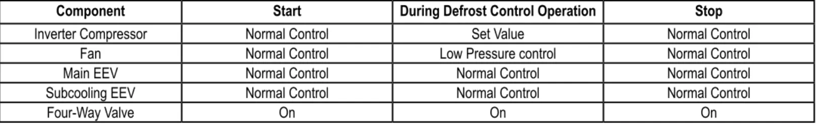
Partial Defrost
The heat exchanger in the outdoor unit(s) is divided into a top part and bottom part for partial defrost operation. Partial defrost operation permits the system to defrost the parts of the heat exchanger separately so heating mode can operate continuously. Each component operates as shown on the below table during partial defrost.
Component Start During Defrost Control Operation Stop
Inverter Compressor Normal Control Set Value Normal Control
Fan Normal Control Low Pressure control Normal Control
Main EEV Normal Control Normal Control Normal Control
Subcooling EEV Normal Control Normal Control Normal Control
Four-Way Valve On On On
Component Start During Defrost Control Operation Stop
Fan ON (Setting) ON (Low) ON (Setting)
Thermo On Unit EEV Normal Control Normal Control Normal Control
Table 8: Outdoor Unit Partial Defrost Control.
Table 9: Indoor Unit Partial Defrost Control.
Partial Defrost Control Stop Operation
1. Partial Defrost Control Operation will run for a maximum of twelve (12) minutes.
2. Partial Defrost Control Operation will stop for the top part of the heat exchanger when the temperature rises higher than the set temperature.
3. Partial Defrost Control Operation will stop for the bottom top part of the heat exchanger when the temperature rises above the set temperature.
Outdoor Unit Functions
SPECIAL CONTROLS
Stop Operation Control
Stop Operation
Component Stop Operation Notes
Inverter Compressor Off
-Fan Stop
-Main EEV 32 Pulse
-Subcooling EEV 16 Pulse Stop (Minimum Pulse)
Four-Way Valve Off
-Stop Operation Control in Cooling Mode
Stop Operation Control in Heating Mode
Component Stop Operation Notes
Inverter Compressor Off
-Fan Stop
-Main EEV 32 Pulse
-Subcooling EEV 16 Pulse Stop (Minimum Pulse)
Four-Way Valve Off When air temperature is >30°C (86°F)
Table 10: Stop Operation Control in Cooling Mode.
Table 11: Stop Operation Control in Heating Mode.
Oil Equalizing Control
Oil equalizing control prevents oil imbalance between the inverter compressors. If the oil level sensors detect different oil levels between the compressors, then the oil equalizing EEV will open for five (5) minutes.
MUL
TI V IV Outdoor Unit Service Manual
PROTECTION CONTROLS
Pressure Protection Control
Pressure Protection Control
Pressure Control in Cooling Mode
Pressure Range Compressor Fan
Pd ≥ 580 psi
548 psi
519 psi Stop Stop
Pd > 548 psi -15 Hz / 10 seconds +100 RPM / 10 seconds
Pd ≥ 510 psi Frequency Hold* +100 RPM / 10 seconds
Pd ≥ 505 psi +2 Hz or less / 10 seconds +100 RPM / 10 seconds
Pd < 505 psi Normal Control
Table 12: High Pressure Control in Cooling Mode.
Pressure Range Compressor Fan
Ps ≤ 14 psi, One (1) minute After Operation Stop Stop
Ps ≤ 118 psi, One (1) minute Before Operation -15Hz / 10 seconds -100 RPM / 10 seconds
Table 13: Low Pressure Control in Cooling Mode.
* Frequency Hold = Frequency (or RPM) is not increasing (can decrease).
Pressure Control in Heating Mode
Pressure Range Compressor Fan
Pd ≥ 581 psi Stop Stop
Pd > 495 psi -15 Hz / 10 seconds -50 RPM / 10 seconds
Table 14: High Pressure Control in Heating Mode.
Table 15: Low Pressure Control in Heating Mode.
Pressure Range Compressor Fan
Ps ≤ 14 psi Stop Stop
Ps ≤ 18 psi -15 Hz / 10 seconds +100 RPM / 10 seconds
Ps ≤ 20 psi Frequency Hold* +100 RPM / 10 seconds
Ps ≤ 28 psi +2 Hz or less / 10 seconds +100 RPM / 10 seconds
Ps ≥ 28 psi Normal Control Normal Control
Outdoor Unit Functions
PROTECTION CONTROLS
Discharge Temperature Control / Inverter Protection Control
Temperature Range Compressor Subcooling EEV Indoor Unit EEV
Tdis > 230°F Off SC, SH Decrease Control SH Decrease Control
Tdis > 226.4°F -5 Hz / 10 seconds SC, SH Decrease Control SH Decrease Control
Tdis ≥ 221°F Frequency Hold* SC, SH Decrease Control SH Decrease Control
Tdis ≤ 212°F Normal Control SC, SH Decrease Control SH Decrease Control
Tdis > 212°F Normal Control SC, SH Decrease Control SH Decrease Control
Discharge Temperature Control
Table 16: Outdoor Unit Discharge Temperature Control.
* Frequency Hold = Frequency (or RPM) is not increasing (can decrease). Tdis = Temperature Discharge.
SC = Subcooling. SH = Superheating.
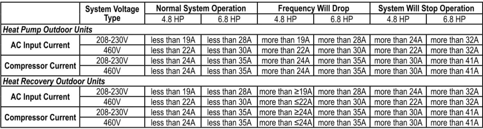
Inverter Protection Control
Table 17: Inverter Protection Control in Cooling Mode. System Voltage
Type Normal System Operation4.8 HP 6.8 HP 4.8 HPFrequency Will Drop6.8 HP System Will Stop Operation4.8 HP 6.8 HP
Heat Pump Outdoor Units
AC Input Current 208-230V 460V less than 19A less than 28A more than 19A more than 28A more than 24A more than 32Aless than 22A less than 30A more than 22A more than 30A more than 22A more than 32A Compressor Current 208-230V 460V less than 24A less than 35A more than 24A more than 35A more than 30A more than 41Aless than 24A less than 35A more than 24A more than 35A more than 30A more than 41A Heat Recovery Outdoor Units
AC Input Current 208-230V 460V less than 19A less than 28Aless than 22A less than 30A more than ≥19Amore than ≤22A more than 28A more than 24A more than 32Amore than 30A more than 22A more than 32A Compressor Current 208-230V 460V less than 24A less than 35Aless than 24A less than 35A more than ≥24Amore than ≤24A more than 35A more than 30A more than 41Amore than 35A more than 30A more than 41A
System Voltage
Type Normal System Operation4.8 HP 6.8 HP 4.8 HPFrequency Will Drop6.8 HP System Will Stop Operation4.8 HP 6.8 HP
Heat Pump Outdoor Units
AC Input Current 208-230V 460V less than 19A less than 28A more than 19A more than 28A more than 24A more than 32Aless than 22A less than 30A more than 22A more than 30A more than 22A more than 32A Compressor Current 208-230V 460V less than 24A less than 35A more than 24A more than 35A more than 30A more than 41Aless than 26A less than 35A more than 26A more than 35A more than 30A more than 41A Heat Recovery Outdoor Units
AC Input Current 208-230V 460V less than ≤19Aless than ≤22A less than 28A more than 19A more than 28A more than 24A more than 32Aless than 30A more than 22A more than 30A more than 22A more than 32A Compressor Current 208-230V 460V less than ≤24Aless than ≤26A less than 35A more than 24A more than 35A more than 30A more than 41Aless than 35A more than 26A more than 35A more than 30A more than 41A Table 18: Inverter Protection Control in Heating Mode.
The tables below display the amperage where the system will operate normally, the amperage where the inverter protection control will cause the frequency to drop, and the amperage where the inverter protection control will shut the system off. AC input current is measured at the inverter compressor (after the point where the current passes through the noise filter).
MUL
TI V IV Outdoor Unit Service Manual
PROTECTION CONTROLS
Phase Detection / Pressure Switch
Phase Detection
Most Multi V systems require three-phase power. The product will display the errors listed in the table below if all three phases / wires aren’t connected correctly (one [1] or more phases missing).
Error Terminal Block Error No.
R S T
Missed Phase X
50 X
X 5
Table 19: Phase Detection Errors.
If errors occur simultaneously on two or more combined outdoor units, only the smaller outdoor unit number will be displayed. Example: If Error No. 50 occurs on both the Master and the Slave 1 outdoor units, “501” displays on the LED (Master: ***1, Slave1: ***2).
Pressure Switch
Main PCB has a pressure sensor switch in the wiring between the inverter compressor and the power relay. The pressure sensor switch is normally on, and has a small electric current from 220V AC.
Outdoor Unit Functions
OTHER CONTROLS
Initial Setup
There are four (4) initial setup steps before operation can begin. All DIP switch settings must be completed before initial setup. Step 1
Factory set value is displayed on the PCB LED for twenty-four (24) seconds.
Turn power on.
Code for the Master outdoor unit is displayed for three (3) seconds. Code for the Slave 1 outdoor unit is displayed for three (3) seconds. Code for the Slave 2 outdoor unit is displayed for three (3) seconds.
Total system capacity is displayed for two (2) seconds.
System type is displayed (2 is default). • Heat Pump = 2
• Heat Recovery = 3
Electrical requirements are displayed. • 208 = 22
• Heat Recovery = 46 Model Type.
14
12
10
36
2
46
1
Step 2
Communication Check: If display follows all sequences as shown above, the communication between the Master and Slave outdoor units is normal. If the LED shows Error Code 104*, check the DIP switch settings and the communication cables between the Master and Slave outdoor units.
Step 3
PCB Error Check: Error check will begin after forty (40) seconds. Master / Slave unit
• All errors of all the units (including Slave) will be shown on the LED.
• If communication between main PCB and inverter PCB isn’t correct, Error Code 52* will be seen on the LED. • If communication between main PCB and fan PCB isn’t normal, Error Code 105* will be seen on the LED. • If any errors are displayed, check corresponding wires / cables.
MUL
TI V IV Outdoor Unit Service Manual
Initial Setup, Continued.
OTHER CONTROLS
Initial Setup
Step 4
Indoor unit auto addressing.
• Auto addressing begins after the red address button on the Main PCB is held for six (6) seconds.
• During auto addressing, the LED on the Main PCB displays "88".
• After auto addressing, the number of indoor units is shown on the LED for thirty (30) seconds. The address of the indoor unit is displayed on each wired remote controller.
Hold red address button down for three (3) seconds.
CN_SMPS2_BL CN_SMPS
CN6~CN10_OPTION PCB
SW01D SW01C SW02C SW03C SW04C
CN_EXT CN_DEBUGGER CN_CNVSS CN3_FLASH WRITE CN2_LGMV
CN_COMP2 CN_COMP1 CN_COMMWIRE CN_POWER
Auto addressing begins. Auto addressing may last up to
fifteen (15) minutes.
46
The number of indoor units is displayed for thirty (30)
seconds.
35
Thirty-five (35) indoor units found. Auto address process is complete. After the number of indoor units has been displayed for thirty (30) seconds, every indoor unit displays its address on a wired remote controller, and the LED on the Main PCB is blank.
Outdoor Unit Functions
Initial Setup, Continued.
Setting the Functions
Select the Mode, Function, Option, or Values using the ◄ and ►buttons. Confirm using the ● button after DIP switch No. 5 is set to on.
Mode Function Option Value Action Remarks
Content Display 1 Content Display 2 Content Display 3 Content Display 4 Implement Display 5
FDD Fdd
Refrigerant Auto Charge
(Cooling) Fn1 - - - - Operate Show theProcess
-Refrigerant Auto Charge
(Heating) Fn2 - - - - Operate Show the Process
-Refrigerant Auto Amount
Judgment (Cooling) Fn3 - - - - Operate Show theProcess
-Refrigerant Auto Amount
Judgment (Heating) Fn4 - - - - Operate Show theProcess
-ITR (Cooling) Fn5 - - - - Operate Show theProcess
-ITR (Heating) Fn6 - - - - Operate Show theProcess
-Installation Func
Cool & Heat Selector Fn1 oFF op1~op2 Selected theOption - - Change theSet Value Blank Saved inEPROM Static Pressure
Compensation Fn2 oFF op1~op3 Selected theOption - - Change theSet Value Blank Saved inEPROM Night Low Noise Fn3 oFF op1~op12 Selected theOption - - Change theSet Value Blank Saved in EPROM
Overall Defrost Fn4 on oFF Selected theOption - - Change theSet Value Blank Saved in EPROM Outdoor Unit Address Fn5 - - 0~255 Set theValue Change theSet Value Blank Saved inEPROM Snow Removal & Rapid
Defrost Fn6 oFF op1~op3 Selected theOption - - Change theSet Value Blank Saved inEPROM Adjusting the Indoor
Unit Capacity Fn7 op1~op2 Selected theOption - - Change theSet Value Blank Saved inEPROM Adjusting Target
Pressure Fn8 op1~op4 Selected theOption - - Change theSet Value Blank Saved inEPROM
SVC SVC
Pump Down SE1 - - - - OperationStart Pd
-Pump Out SE2 - - - - OperationStart Po
-Vacuum mode SE3 - - - - OperationStart uRcc
-Backup SE4 unit inv1~inv2 Selected theOption - - OperationStart on off Saved inEPROM
Forced oil return SE5 - - - - OperationStart o1
-Forced defrost SE6 - - - - OperationStart dEF
-Cycle data view SE7 op1~op7 - - - Show inLED Show EachNumericalValue in Process
-DIP-SW01 LED
SW01C ( : Confirm) SW02C ( : Backward) SW03C ( : Forward) SW04C ( : Cancel)
SW01D (Reset)
ON OFF
OTHER CONTROLS
MUL
TI V IV Outdoor Unit Service Manual
OTHER CONTROLS
Emergency Operation
If an inverter compressor is not operating, the system can still run by using one of two methods. Automatic Emergency Operation (Automatic Backup Function)
If an outdoor unit detects an inverter compressor error during operation, the automatic backup mode is initiated. 1. Inverter 1 compressor automatic emergency operation.
2. Inverter 2 compressor automatic emergency operation.
Emergency Operation
Backup Mode Cancellation
Select the “off” Action By Using the ►and◄ Buttons, then Push the ● Button.
• Do not run the system under emergency operation with an inverter compressor failure for more than 48 hours. It may cause compressor failure within the other outdoor units.
• During the emergency operation, cooling / heating capacity may be reduced. If Slave 1 Outdoor Unit Inverter Compressor Fails
1. Ensure Slave 1 Outdoor Unit PCB No. 5 DIP Switch is Set to ON.
2. Select the “SVC” Mode By Using the ►and◄ Buttons, then Push the ● Button.
3. Select the “Se4” Function By Using the ►and◄ Buttons, then Push the ● Button.
4. Select the “inv1” Option By Using the ►and◄ Buttons, then Push the ● Button.
5. Select “Action” By Using the ►and◄ Buttons, then Push the ●
Button.
If Slave 2 Outdoor Unit Fails
1. Ensure Slave 2 Outdoor Unit PCB No. 5 DIP Switch is Set to ON.
2. Select the “SVC” Mode By Using the ►and◄ Buttons, then Push the ● Button.
3. Select the “Se4” Function By Using the ►and◄ Buttons, then Push the ● Button.
4. Select the “inv1” Option By Using the ►and◄ Buttons, then Push the ● Button.
5. Select “Action” By Using the ►and◄ Buttons, then Push the ●
Button.
SLAVE1
INV1 INV2 INV1 INV2 INV1 INV2 INV1 INV2 INV1 INV2 INV1 INV2
MASTER SLAVE1 SLAVE2 MASTER SLAVE2
Manual Emergency Operation (Manual Backup Function)
1. Verify which compressor is malfunctioning (refer to the Troubleshooting section in the back of this manual). 2. Turn off the power.
3. Set the DIP switch of the defective outdoor unit following the instructions below. 4. Turn on the power.
Outdoor Unit Functions
Fault Detection Diagnosis (FDD) Checklist1. A test run should be performed before running the automatic address procedure. After installation, recheck the auto addressing. 2. After the power is turned on, the MICOM data is reset, and communications with the indoor units will commence in three (3) minutes. 3. Indoor units must be series seven (7) and higher.
4. The results and errors are displayed only on the Master outdoor unit Main PCB LED for the FDD test run.
5. Change the DIP switch to OFF, then press the black button for two (2) seconds to reset all data and return to operation standby.
6. To reset if the test run must be shut off because of an error, press the SW04C (X: Cancel) and SW01C (●: execute) button simultaneously
for more than five (5) seconds.
7. After the test run is finished, the results are displayed for ninety (90) seconds, and all indoor units are turned off. 8. If all FDD functions wish to be applied, first press the main PCB reset button for three (3) minutes.
9. If LGMV version 7.0.3 or later is used, a normal test run can be operated.
OTHER CONTROLS
MUL
TI V IV Outdoor Unit Service Manual
Refrigerant Auto Charge
This function can be used to charge a suitable amount of refrigerant in the system through automatic cycle operation. Use the refrigerant auto charge function if the refrigerant amount is not correct after the system is serviced, if there is a leak in the piping, etc.
Refrigerant charging time can be different depending on the amount necessary. Approximate charge time is about 1.5 minutes per pound.
OTHER CONTROLS
Refrigerant Auto Charge
After installing and servicing the system, calculate and charge the correct amount of refrigerant.
Yes
Yes Yes
Yes
Yes
Yes Cooling
Heating
No
No No
No
No No
No Start
Display.
Airflow mode runs for one (1) minute
Start refrigerant charge.
Is the cycle unstable?
Reverse switch, indoor unit OFF. Start system full load operation. Operate refrigerant amount judge mode.
(25 minute operation) Temperature/load conditions are suitable?
Is the cycle stable? Operation time morethan 40 minutes?
Refrigerant amount OK?
More than 12 minutes after E10 display.
SW02C,SW03C push button for 3
seconds.
Refrigerant amount
Outdoor Unit Functions
Refrigerant Auto Charge, Continued.
Refrigerant Charge Procedure
1. Prepare manifold, refrigerant, and scale (sold separately). 2. Connect manifold to refrigerant charge ports as seen in the
figures.
3. Connect Manifold and refrigerant.
4. Perform the air purge procedure for each manifold hose. 5. When “E10” is displayed, open the valve and charge the system
with refrigerant.
OTHER CONTROLS
• Follow the procedures indicated on this page when charging refrigerant.
• If ambient conditions are out of the operating temperature range, Auto Charge may not operate properly.
• Outdoor Unit Operating Temperature Range: Cooling = 32~109°F; Heating = 14~75°F.
• Indoor Unit Operating Temperature Range: Cooling = 65~90°F;
Heating = 50~81°F.
• If the system continuously turns off because of excessive low pressure levels before “E10” is displayed, the system does not have the appropriate amount of refrigerant. Add about 15% of the estimated refrigerant amount, and try the procedure again.
• Press SW04C (X: Cancel) button down and push DIP switch down after the auto refrigerant charge function ends.
When performing the leak test and air purge, use a vacuum pump or an inert gas such as nitrogen. If oxygen, compressed air, or flamma
-ble gas are used, there is a possibility of fire, explosion, personal injury, and death.
Gas pipe Liquid pipe
Low Pressure Gas pipe
High Pressure Gas pipe Liquid pipe
Refrigerant Auto Charge
Figure 3: Multi V IV Heat Pump Refrigerant Charge Procedure.
Figure 4: Multi V IV Heat Recovery Refrigerant Charge Procedure.
• When you charge refrigerant, use the specified equipment. • Use the wired remote control to set the main unit.
• During indoor unit operation, system must be in Thermo on.
• If outdoor unit switched to defrost mode while the auto refrigerant charge function was operating, restart function after defrost mode is finished.
MUL
TI V IV Outdoor Unit Service Manual
Refrigerant Amount Auto Measure
This function allows the system to automatically measure refrigerant levels through system operation. Refrigerant Amount Auto Measure can be used to see if the system has been overcharged or underchanged, and can be used with the Refrigerant Auto Charge function.
OTHER CONTROLS
Refrigerant Amount Auto Measure
Refrigerant Amount Auto Measure function will stop if the indoor unit combination ratio and the operating temperature range are not within manufacturer’s allowable parameters.
• Indoor unit combination ratio: 80~130%
• Outdoor unit operating temperature range: Cooling = 32~109°F; Heating = 14~75°F.
Refrigerant Amount Auto Measure function runs for 15 minutes at full load operation; refrigerant levels can be measured directly under special cases.
• Press SW04C (X: Cancel) button and turn the DIP switch to OFF after the function ends. Yes
Yes
Yes Yes
No
No No
Start
End Fan mode operates for
one (1) minute.
Start system full load operation (operates for 15 minutes).
Refrigerant amount is measured. Is the cycle unstable?
Operation stopped and the results are displayed. Temperature OK?
Is the cycle stable? After 40 minutes?
End Cooling
Heating
• LED will display if the system has a refrigerant overcharge or a refrigerant undercharge, as well as the percentage of over- or undercharge per the total amount of refrigerant.
Ex. 1: 20% refrigerant overcharge need to remove Ex. 2: 20% refrigerant undercharge need to charge Ex. 3: No adjustment necessary
Outdoor Unit Functions
Initial Test Run (ITR) (Cooling)
ITR (Cooling) function checks for normal cooling operation of certain parts and the overall system. Use LGMV to check and save data.
Assessment Code Display
ITR (Cooling)
Indoor Unit EEV
OK 5-Cn 5-cn
Not Appropriate 5-C1 5-c1
Cannot Confirm 5-CF 5-cF
Refrigerant
More Than Correct Amount Ex: 20% 20
Less Than Correct Amount Ex: -15% -15
No Adjustment Required 00 00
Cannot Confirm 3-CF 3-cF
Start
Are all indoor units operating in fan mode for one (1) minute?
Check temperature. Yes
No
System off Stop operation and assess
the results.
Verify indoor unit EEV operation.
Check for four-way valve switchover. Check all indoor unit refrigerant
operation and save the data. Review (All-1) indoor unit operation and save the data
Review one (1) indoor unit operation and save the data
OTHER CONTROLS
Initial Test Run (ITR) (Cooling)
Table 20: ITR (Cooling) Codes.
Manufacturer’s Operating Temperature range (Error occurs out of operating temperature range):
• Indoor Units = 65~90°F • Outdoor Units = 32~109°F
DIP switch 5 enables the function mode. If the function is not used, set DIP switch 5 to off, and reset the power.
If an error occurs with an indoor unit, operate that in-door unit in fan mode, but make sure the auto address number of that indoor unit does not display.
MUL
TI V IV Outdoor Unit Service Manual
OTHER CONTROLS
Initial Test Run (ITR) (Heating)
Initial Test Run (ITR) (Heating)
ITR (Heating) function checks for normal heating operation of certain parts and the overall system. Use LGMV to check and save data.
Start
Check t emperatures.
System off
Are all indoor units operating in
fan mode for one (1) minute?
Check all indoor unit refrigerant
operation and save the data.
Review (All-1) indoor unit
operation and save the data
Review one (1) indoor unit
operation and save the data
Check for four-way valve
switchover.
Verify indoor unit EEV operation.
Stop operation and assess
the results.
Manufacturer’s Operating Temperature range (Error occurs out of operating temperature range): • Indoor Units = 65~90°F
• Outdoor Units = 14~75°F
Outdoor Unit Functions
OTHER CONTROLS
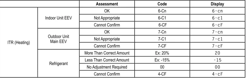
Initial Test Run (ITR) (Heating) / Fault Detection Diagnosis (FDD) Code
Assessment Code Display
ITR (Heating)
Indoor Unit EEV
OK 6-Cn 6-cn
Not Appropriate 6-C1 6-c1
Cannot Confirm 6-CF 6-cF
Outdoor Unit Main EEV
OK 7-Cn 7-cn
Not Appropriate 7-C1 7-c1
Cannot Confirm 7-CF 7-cF
Refrigerant
More Than Correct Amount Ex: 20% 20
Less Than Correct Amount Ex: -15% -15
No Adjustment Required 00 00
Cannot Confirm 4-CF 4-cF
Table 21: ITR (Heating) Codes.
Initial Test Run (ITR) (Heating), continued.
Fault Detection Diagnosis (FDD) Codes
Error Codes Display Problem
E01 E01 Indoor unit combination capacity is >130% or <80% less than outdoor unit rated capacity.
E02 E02 System is unstable.
E03 E03 Temperature range error.
E04 E04 Can’t operate FDD function for defrost.
E05 E05 Error occurs during sensor check function.
E06 E06 Occurs if only one indoor unit is present.
E07 E07 Occurs if the button is not pressed for auto refrigerant charge function. E08 E08 FDD was forced to terminate or refrigerant auto charge terminated normally.
E09 E09 System off / wait to operate FDD function.
E10 E10 Need additional refrigerant.
System Error Same as Normal Operation System error has occured
MUL
TI V IV Outdoor Unit Service Manual
OTHER CONTROLS
Multi V ITR Result Report
Multi V Start up Confirmation
Date
Company Name & Address Telephone Name
Project Manager ConsultantInstaller Supervisor Product
Model Model No. Position
Outdoor Unit Indoor Unit
HR Unit
Test Run Results
Operation Mode %ITR_6 All IDU Operation 1 IDU Operation STEP %ITR_122
Check Items Min. Max. Average Min. Max. Average OK/NG Criterion For Judgment
Temp. Condition ODU Air TempIDU Air Temp 68~86°F 221°F
Indoor Unit IDU pipe outlet tempIDU pipe inlet Temp IDU LEV Openess
Outdoor Unit
Pressure High Pressure
522.1 psi↓(Cool) 333.6 psi↓(Heat)
Low Pressure 188.5 psi ↑(Cool)29 psi ↑(Heat)
COMP
COMP Operate Combination CT Value
ODU #1 Comp1
24A ↓
ODU #1 Comp2 ODU #2 Comp1 ODU #2 Comp2 ODU #3 Comp1 ODU #3 Comp2 Discharge Temp.
ODU #1 Comp1
122~176°F ODU #1 Comp2
ODU #2 Comp1 ODU #2 Comp2 ODU #3 Comp1 ODU #3 Comp2
Main Voltage R-phaseT-phase 342~456 V
Main Current R-phaseT-phase 20A ↓
Discharge Superheat ODU #1ODU #2 122~176°F, Heat
ODU #3
Suction Superheat ODU #1ODU #2 33~45°F, Heat33°F ↑, Cool
ODU #3
ODU LEV Open ODU #1ODU #2
ODU #3 Refrigerant Check
Main EEV Check IDU EEV Check
Multi V ITR Result Report
Outdoor Unit Functions
OTHER CONTROLS
Multi V ITR Result Report
Multi V ITR Result Report, Continued.
Follow the Procedure:
MUL
TI V IV Outdoor Unit Service Manual
Pump Down for Heat Pump Systems
The Pump Down function pulls the refrigerant in the piping system to the outdoor unit(s). Use this procedure to store refrigerant in the system in the outdoor unit in case of a leak or when replacing an indoor unit.
OTHER CONTROLS
Pump Down
Close the liquid pipe service valve on each outdoor unit. Open the gas (vapor) pipe service valve on each outdoor unit.
Set the DIP switch on the Master outdoor unit, then reset the power (Refer to DIP switch setting information).
All indoor units are in cooling mode. Press the red SW01C button.
*Current low pressure
*Current low pressure
*Current low pressure <45 psi (LED will blink) 1
2 Yes
Low pressure < 34 psi
Turn all indoor units and outdoor units off.
Set DIP switch to off and reset power.
Pump down completed. Is the target low
pressure level satisfied?
Heat Pump Service Valve Setting
No
Close
Liquid Pipe Gas (Vapor) Pipe
Open
Close Close
Liquid Pipe
Heat Pump Service Valve Setting
Gas (Vapor) Pipe
Press the red SW01C button.
1. If low pressure falls below 45 psi, immediately close the gas (vapor) pipe service valves on all outdoor units.
2. If low pressure falls below 34 psi, the system turns off automatically. Immediately close the gas (vapor) pipe service valves on the outdoor units.
• Use the Pump Down function while ambient conditions are within the manufacturer’s operating temperature ranges: Indoor Units = 68~90°F; Outdoor Units = 41~104°F.
• Ensure that the indoor units do not run in thermo off mode during Pump Down.
Outdoor Unit Functions
OTHER CONTROLS
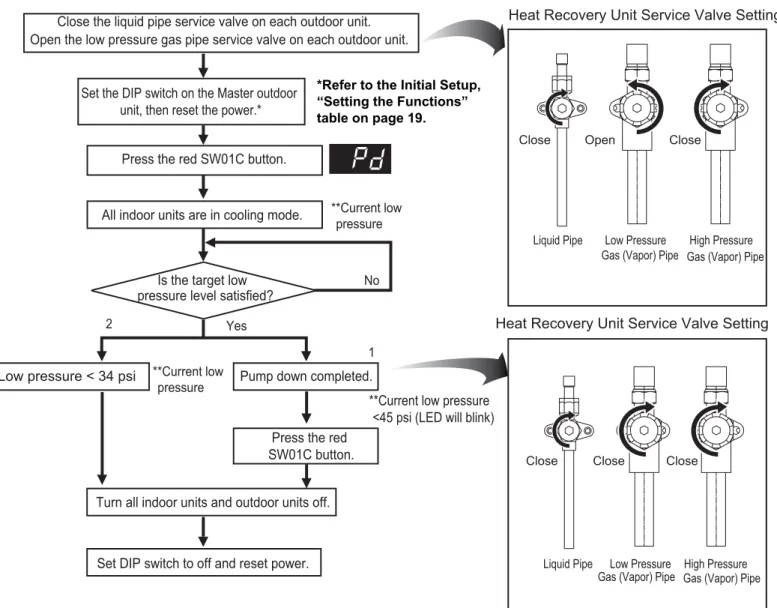
Pump Down for Heat Recovery Systems
The Pump Down function pulls the refrigerant in the piping system to the outdoor unit(s). Use this procedure to store refrigerant in the system in the outdoor unit in case of a leak or when replacing an indoor unit.
**Current low pressure
**Current low pressure
1
2 Yes
Heat Recovery Unit Service Valve Setting
No
Close Close
Liquid Pipe Open
High Pressure Low Pressure
Gas (Vapor) Pipe
Close Close Close
Liquid Pipe Low Pressure High Pressure
Heat Recovery Unit Service Valve Setting Close the liquid pipe service valve on each outdoor unit.
Open the low pressure gas pipe service valve on each outdoor unit.
Gas (Vapor) Pipe
Set the DIP switch on the Master outdoor unit, then reset the power.*
All indoor units are in cooling mode. Press the red SW01C button.
Is the target low pressure level satisfied?
Low pressure < 34 psi Pump down completed. Press the red SW01C button.
**Current low pressure <45 psi (LED will blink)
Turn all indoor units and outdoor units off. Set DIP switch to off and reset power.
Gas (Vapor) Pipe Gas (Vapor) Pipe
1. If low pressure falls below 45 psi, immediately close the gas (vapor) pipe service valves on all outdoor units.
2. If low pressure falls below 34 psi, the system turns off automatically. Immediately close the gas (vapor) pipe service valves on the outdoor units.
• Use the Pump Down function while ambient conditions are within the manufacturer’s operating temperature ranges: Indoor Units = 68~90°F; Outdoor Units = 41~104°F.
• Ensure that the indoor units do not run in thermo off mode during Pump Down.
Pump Down
*Refer to the Initial Setup, “Setting the Functions” table on page 19.
MUL
TI V IV Outdoor Unit Service Manual
OTHER CONTROLS
Pump Out
Pump Out for Heat Pump Systems
The Pump Out function pushes refrigerant from a malfunctioning outdoor unit to other outdoor units and indoor units. Use this function in the event of an outdoor unit compressor failure, if a part is defective and needs to be replaced, or if there is a leak.
1. If low pressure falls beiow 45 psi (the LED will blink), close the gas service valves on all outdoor units immediately.
2. If low pressure falls below 34 psi, the system turns off automatically. Immediately close the gas (vapor) pipe service valves on the outdoor units.
1
2 Yes
No
Pump out completed.
Close Close
Liquid Pipe Close
Liquid Pipe Gas (Vapor) Pipe
Open **Current low
pressure
**Current low pressure
Close the liquid pipe service valve on each outdoor unit. Open the gas (vapor) pipe service valve on each outdoor unit.
Heat Pump Service Valve Setting
Heat Pump Service Valve Setting
Gas (Vapor) Pipe Set the DIP switch on the Master
outdoor unit, then reset the power.*
All indoor units are in heating mode. Press the red SW01C button.
Is the target low pressure level satisfied?
**Current low pressure <45 psi (LED will blink) Press the red
SW01C button. Turn all indoor units and outdoor units off.
Set DIP switch to off and reset power. Low pressure >34 psi
• Use the Pump Out function while ambient conditions are within the manufacturer’s operating temperature ranges: Indoor Units = 50~86°F; Outdoor Units = 41~104°F.
• Ensure that the indoor units do not run in thermo off mode during Pump Out (in case low pressure does not satisfy levels). • Maximum operation time of Pump Out takes two (2) to five (5) minutes after the compressor starts.
*Refer to the Initial Setup, “Setting the Functions” table on page 19.
Outdoor Unit Functions
OTHER CONTROLS
Pump Out
Pump Out for Heat Pump Systems, Continued.
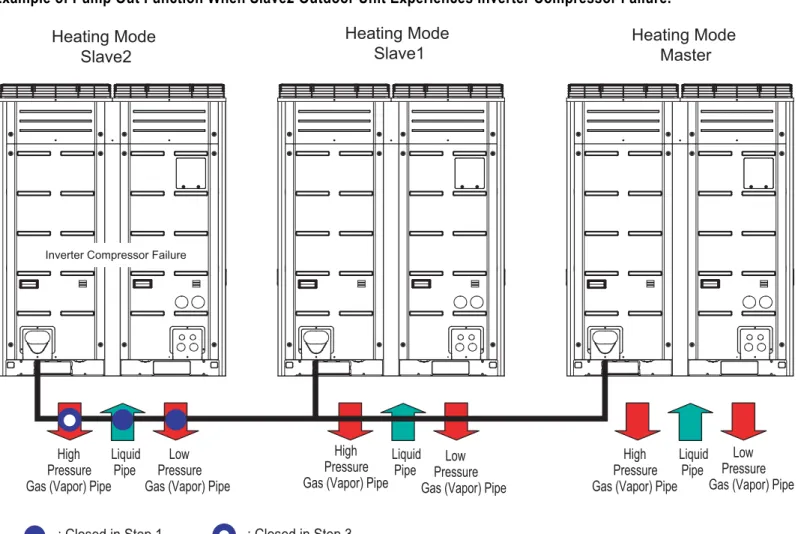
Example of Pump Out Function When Slave2 Outdoor Unit Experiences Inverter Compressor Failure.
1. Close the liquid pipe of the outdoor unit for Pump Out operation. Open the gas valve.
2. Operate Pump Out function.
3. Close the gas (vapor) pipe of unit after Pump Out is complete. 4. Replace Inverter compressor and perform vacuum.
5. Add refrigerant using the Refrigerant Auto Charge Function.
Gas Liquid
Pipe
Gas
Liquid
Pipe
Gas
(Vapor)
Pipe
Liquid
Pipe
Heating Mode
Slave2 Heating ModeSlave1 Heating ModeMaster
(Vapor)
Pipe
(Vapor)
Pipe
= Closed = Open
Inverter Compressor Failure
Liquid Pipe Gas (Vapor) Pipe
Service Port
Refrigerant Charge Valve
Figure 5: Close Up of Heat Pump Service Ports and Refrigerant Charge Valve.
MUL
TI V IV Outdoor Unit Service Manual
OTHER CONTROLS
Pump Out
Pump Out for Heat Recovery Systems
The Pump Out function pushes refrigerant from a malfunctioning outdoor unit to other outdoor units and indoor units. Use this function in the event of an outdoor unit compressor failure, if a part is defective and needs to be replaced, or if there is a leak.
1
2 Yes
No **Current low pressure
**Current low pressure
Close Close
Liquid Pipe High Pressure
Gas Pipe
Close Close
Liquid Pipe High Pressure
Gas Pipe Open
Close
Low Pressure Gas Pipe Low Pressure
Gas Pipe
Heat Recovery Service Valve Setting
Heat Recovery Service Valve Setting Close the liquid pipe service valve on each outdoor unit. Open
the high pressure gas pipe service valve on each outdoor unit. Set the DIP switch on the Master
outdoor unit, then reset the power.*
All indoor units are in heating mode. Press the red SW01C button.
Is the target low pressure level satisfied?
Pump out completed.
**Current low pressure <45 psi (LED will blink) Press the red
SW01C button. Turn all indoor units and outdoor units off.
Set DIP switch to off and reset power. Low pressure >34 psi
1. If low pressure falls beiow 45 psi (the LED will blink), close the gas (vapor) service valves on all outdoor units immediately. 2. If low pressure falls below 34 psi, the system turns off automatically. Immediately close the gas (vapor) pipe service valves on the
outdoor units.
• Use the Pump Out function while ambient conditions are within the manufacturer’s operating temperature ranges: Indoor Units = 50~86°F; Outdoor Units = 41~104°F.
• Ensure that the indoor units do not run in thermo off mode during Pump Out (in case low pressure does not satisfy levels). • Maximum operation time of Pump Out takes two (2) to five (5) minutes after the compressor starts.
*Refer to the Initial Setup, “Setting the Functions” table on page 19.
Outdoor Unit Functions
OTHER CONTROLS
Pump Out
Pump Out for Heat Recovery Systems, Continued.
Example of Pump Out Function When Slave2 Outdoor Unit Experiences Inverter Compressor Failure.
High Pressure Gas (Vapor) Pipe
Low Pressure Gas (Vapor) Pipe Liquid
Pipe LiquidPipe
: Closed in Step 1 : Closed in Step 3
Liquid Pipe Heating Mode
Slave2
Heating Mode
Slave1 Heating ModeMaster
Inverter Compressor Failure
High Pressure Gas (Vapor) Pipe
High Pressure Gas (Vapor) Pipe Low
Pressure Gas (Vapor) Pipe
Low Pressure Gas (Vapor) Pipe
1. Close liquid pipe and low pressure gas pipe of the outdoor unit for Pump Out operation.
2. Operate Pump Out function.
3. Close high pressure gas pipe of unit after Pump Out is complete.
4. Recover refrigerant in suction port after opening the low pressure gas pipe of the corresponding outdoor unit
5. Replace Inverter compressor and perform vacuum.
6. Add refrigerant using the Refrigerant Auto Charge Function.
Figure 6: Close Up of Heat Pump Service Ports and Refrigerant Charge
Valve. .
Low Pressure Gas (Vapor) Pipe Liquid Pipe High Pressure Gas (Vapor) Pipe
MUL
TI V IV Outdoor Unit Service Manual
Auto Back Up Function (Inverter Compressor)
The Auto Back Up Function allows the system to operate in case of inverter failure, backing up the compressor (operating on the defective compressor is halted). Error can be displayed every six (6) hours.
• Request service immediately if error occurs.
• Auto Back Up Function is set up to one inverter compressor.
• When Auto Back Up Function begins, the error code(s) display(s) for ten (10) minutes every six (6) hours. • Error will display continuously at the corresponding outdoor unit(s).
Inverter compressor failure
Error Nos. 21, 22, 26, 27 may occur). Operation
Auto Back up Operation Initiates.
Indoor units / outdoor units display error for ten (10) minutes.
Error clears from indoor unit controller, indoor unit operation possible.
No Yes
Example: Slave1 unit Inverter Compressor 1 start fails (Error No. 21 occurs)
Time > Six (6) Hours
(Repeats)
Error Compressor Error number Unit (1: Master, 2: Slave1, 3: Slave 2)