C
Document 5202408/05/2005
Fire Alarm Control Panel
IFC-3030
Installation Manual
Fire Alarm System Limitations
While a fire alarm system may lower insurance rates, it is not a substitute for fire insurance!
An automatic fire alarm system—typically made up of smoke detectors, heat detectors, manual pull stations, audible warning devices, and a fire alarm control panel with remote notification capability—can provide early warning of a develop-ing fire. Such a system, however, does not assure protection against property damage or loss of life resulting from a fire. The Manufacturer recommends that smoke and/or heat detec-tors be located throughout a protected premise following the recommendations of the current edition of the National Fire Protection Association Standard 72 (NFPA 72), manufacturer's recommendations, State and local codes, and the recommen-dations contained in the Guide for Proper Use of System Smoke Detectors, which is made available at no charge to all installing dealers. A study by the Federal Emergency Man-agement Agency (an agency of the United States government) indicated that smoke detectors may not go off in as many as 35% of all fires. While fire alarm systems are designed to pro-vide early warning against fire, they do not guarantee warning or protection against fire. A fire alarm system may not provide timely or adequate warning, or simply may not function, for a variety of reasons:
Smoke detectors may not sense fire where smoke cannot reach the detectors such as in chimneys, in or behind walls, on roofs, or on the other side of closed doors. Smoke detectors also may not sense a fire on another level or floor of a building. A second-floor detector, for example, may not sense a first-floor or basement fire.
Particles of combustion or “smoke” from a developing fire may not reach the sensing chambers of smoke detectors because:
• Barriers such as closed or partially closed doors, walls, or chimneys may inhibit particle or smoke flow.
• Smoke particles may become “cold,” stratify, and not reach the ceiling or upper walls where detectors are located. • Smoke particles may be blown away from detectors by air
outlets.
• Smoke particles may be drawn into air returns before reaching the detector.
The amount of “smoke” present may be insufficient to alarm smoke detectors. Smoke detectors are designed to alarm at various levels of smoke density. If such density levels are not created by a developing fire at the location of detectors, the detectors will not go into alarm.
Smoke detectors, even when working properly, have sensing limitations. Detectors that have photoelectronic sensing chambers tend to detect smoldering fires better than flaming fires, which have little visible smoke. Detectors that have ion-izing-type sensing chambers tend to detect fast-flaming fires better than smoldering fires. Because fires develop in different ways and are often unpredictable in their growth, neither type of detector is necessarily best and a given type of detector may not provide adequate warning of a fire.
Smoke detectors cannot be expected to provide adequate warning of fires caused by arson, children playing with matches (especially in bedrooms), smoking in bed, and violent explosions (caused by escaping gas, improper storage of flammable materials, etc.).
Heat detectors do not sense particles of combustion and alarm only when heat on their sensors increases at a predeter-mined rate or reaches a predeterpredeter-mined level. Rate-of-rise heat detectors may be subject to reduced sensitivity over time. For this reason, the rate-of-rise feature of each detector should be tested at least once per year by a qualified fire pro-tection specialist. Heat detectors are designed to protect property, not life.
IMPORTANT! Smoke detectors must be installed in the same room as the control panel and in rooms used by the sys-tem for the connection of alarm transmission wiring, communi-cations, signaling, and/or power. If detectors are not so located, a developing fire may damage the alarm system, crip-pling its ability to report a fire.
Audible warning devices such as bells may not alert people if these devices are located on the other side of closed or partly open doors or are located on another floor of a building. Any warning device may fail to alert people with a disability or those who have recently consumed drugs, alcohol or medica-tion. Please note that:
• Strobes can, under certain circumstances, cause seizures in people with conditions such as epilepsy.
• Studies have shown that certain people, even when they hear a fire alarm signal, do not respond or comprehend the meaning of the signal. It is the property owner's responsi-bility to conduct fire drills and other training exercise to make people aware of fire alarm signals and instruct them on the proper reaction to alarm signals.
• In rare instances, the sounding of a warning device can cause temporary or permanent hearing loss.
A fire alarm system will not operate without any electrical power. If AC power fails, the system will operate from standby batteries only for a specified time and only if the batteries have been properly maintained and replaced regularly.
Equipment used in the system may not be technically com-patible with the control panel. It is essential to use only equip-ment listed for service with your control panel.
Telephone lines needed to transmit alarm signals from a premise to a central monitoring station may be out of service or temporarily disabled. For added protection against tele-phone line failure, backup radio transmission systems are rec-ommended.
The most common cause of fire alarm malfunction is inade-quate maintenance. To keep the entire fire alarm system in excellent working order, ongoing maintenance is required per the manufacturer's recommendations, and UL and NFPA stan-dards. At a minimum, the requirements of NFPA 72 shall be followed. Environments with large amounts of dust, dirt or high air velocity require more frequent maintenance. A main-tenance agreement should be arranged through the local man-ufacturer's representative. Maintenance should be scheduled monthly or as required by National and/or local fire codes and should be performed by authorized professional fire alarm installers only. Adequate written records of all inspections should be kept.
Installation Precautions
Adherence to the following will aid in problem-free installation with long-term reliability:
WARNING - Several different sources of power can be connected to the fire alarm control panel. Disconnect all sources of power before servicing. Control unit and associ-ated equipment may be damaged by removing and/or insert-ing cards, modules, or interconnectinsert-ing cables while the unit is energized. Do not attempt to install, service, or operate this unit until manuals are read and understood.
CAUTION - System Re-acceptance Test after Software Changes: To ensure proper system operation, this product must be tested in accordance with NFPA 72 after any pro-gramming operation or change in site-specific software. Re-acceptance testing is required after any change, addition or deletion of system components, or after any modification, repair or adjustment to system hardware or wiring. All compo-nents, circuits, system operations, or software functions known to be affected by a change must be 100% tested. In addition, to ensure that other operations are not inadvertently affected, at least 10% of initiating devices that are not directly affected by the change, up to a maximum of 50 devices, must also be tested and proper system operation verified.
This system meets NFPA requirements for operation at 0-49º C/32-120º F and at a relative humidity (non condensing) of 85% at 30°C (86°F) per NFPA, and 93% ± 2% at 32°C ± 2°C (89.6°F ± 1.1°F) per ULC. However, the useful life of the sys-tem's standby batteries and the electronic components may be adversely affected by extreme temperature ranges and humid-ity. Therefore, it is recommended that this system and its peripherals be installed in an environment with a normal room temperature of 15-27º C/60-80º F.
Verify that wire sizes are adequate for all initiating and indi-cating device loops. Most devices cannot tolerate more than a 10% I.R. drop from the specified device voltage.
Like all solid state electronic devices, this system may operate erratically or can be damaged when subjected to light-ning induced transients. Although no system is completely immune from lightning transients and interference, proper grounding will reduce susceptibility. Overhead or outside aerial wiring is not recommended, due to an increased susceptibility to nearby lightning strikes. Consult with the Technical Ser-vices Department if any problems are anticipated or encoun-tered.
Disconnect AC power and batteries prior to removing or inserting circuit boards. Failure to do so can damage circuits.
Remove all electronic assemblies prior to any drilling, filing, reaming, or punching of the enclosure. When possible, make all cable entries from the sides or rear. Before making modifi-cations, verify that they will not interfere with battery, trans-former, or printed circuit board location.
Do not tighten screw terminals more than 9 in-lbs. Over-tightening may damage threads, resulting in reduced ter-minal contact pressure and difficulty with screw terter-minal removal.
This system contains static-sensitive components. Always ground yourself with a proper wrist strap before han-dling any circuits so that static charges are removed from the body. Use static suppressive packaging to protect electronic assemblies removed from the unit.
Follow the instructions in the installation, operating, and pro-gramming manuals. These instructions must be followed to avoid damage to the control panel and associated equipment. FACP operation and reliability depend upon proper installation.
Precau-L-4-2005.fm
FCC Warning
WARNING: This equipment generates, uses, and can radiate radio frequency energy and if not installed and used in accordance with the instruction manual may cause interference to radio communications. It has been tested and found to comply with the limits for class A computing devices pursuant to Subpart B of Part 15 of FCC Rules, which is designed to provide reasonable protection against such interference when devices are operated in a commercial environment. Operation of this equipment in a residential area is likely to cause interfer-ence, in which case the user will be required to correct the interference at his or her own expense.
Canadian Requirements
This digital apparatus does not exceed the Class A limits for radiation noise emissions from digital apparatus set out in the Radio Interference Regulations of the Cana-dian Department of Communications.
Le present appareil numerique n'emet pas de bruits radi-oelectriques depassant les limites applicables aux appa-reils numeriques de la classe A prescrites dans le Reglement sur le brouillage radioelectrique edicte par le ministere des Communications du Canada.
HARSH™, NIS™, Notifier Integrated Systems™, NOTI•FIRE•NET™, and ONYXWorks™ are all trademarks; and FlashScan®, NION®, NOTIFIER®,
ONYX®, UniNet®, VeriFire®, and VIEW® are all registered trademarks of Honeywell International Inc. Echelon® is a registered trademark and LonWorks™
is a trademark of Echelon Corporation. ARCNET® is a registered trademark of Datapoint Corporation. Microsoft® and Windows® are registered trademarks of the Microsoft Corporation. LEXAN® is a registered trademark of GE Plastics, a subsidiary of General Electric Company.
Documentation Feedback
Your feedback helps us keep our documentation up-to-date and accurate. If you have any
com-ments or suggestions about our online Help or printed manuals, you can email us.
Please include the following information:
•
Product name and version number (if applicable)
•
Printed manual or online Help
•
Topic Title (for online Help)
•
Page number (for printed manual)
•
Brief description of content you think should be improved or corrected
•
Your suggestion for how to correct/improve documentation
Send email messages to:
FireSystems.TechPubs@honeywell.com
Please note this email address is for documentation feedback only. If you have any technical
issues, please contact Technical Services.
Table of Contents
Section 1: About This Manual... 7
1.1: Standards and Other Documents...7
1.2: Supplemental Documentation...8
1.3: Cautions and Warnings ...9
Section 2: System Overview ... 11
2.1: System Description...11
2.1.1: Standard Features ...11
2.1.2: Options ...11
2.1.3: System Limitations ...11
2.2: System Components ...12
2.3: Product Diagram ...13
2.3.1: Main Power Supply ...14
2.4: System Cabinets...15
2.5: Compatible Equipment ...16
Notifier/Johnson Controls Compatible Equipment ...16
System Sensor Compatible Equipment ...17
Section 3: Installation... 19
3.1: Preparing for Installation ...19
3.2: Installation Checklist ...19
3.3: Mounting a Cabinet ...20
3.4: Laying Out Equipment in Cabinet and Chassis ...21
3.5: Attaching the CPU & Chassis...22
Mounting Chassis in Backbox...23
3.5.1: Memory-Backup Battery ...23
3.6: Attaching Option Boards ...24
Mounting procedures...24
3.7: Attaching Panel Circuit Modules...25
3.7.1: Overview ...25
3.7.2: Mount Expander Boards...26
3.7.3: Installing a Multi-layer Module into the Chassis ...26
3.7.4: Connecting Expander Row Ribbon Cables ...28
3.8: Initiating Device Circuits with IZM-8RK/IZE-A...29
3.8.1: Style B Field Wiring (Up to 8 Style B IDCs) ...29
3.8.2: Style D Field Wiring ...30
3.9: NACs with ICM-4RK⁄ICE-4 ...31
3.9.1: Power Supply Connections...32
3.10: Form-C Relays on the CPU ...33
3.11: Form-C Relays with CRM-4RK/CRE-4...34
3.12: Form-C Relays with Auxiliary Relay Module (ARM-4) ...35
3.12.1: Overview ...35
3.12.2: Installation ...35
3.12.3: Field Wiring an Auxiliary Relay Module...36
3.13: Notification Appliance Circuit Current Limitations ...36
3.14: Connecting Specific Option Boards ...37
3.14.1: Network Control Module...37
3.14.2: Loop Control Module, Loop Expander Module...37
Mounting Instructions ...37
Setting SLC Loop Number...38
Enabling External Power Supervision...38
3.15: Connecting Power Sources and Outputs...41
3.15.1: Overview ...41
3.15.2: Connecting the Power Supply ...42
Table of Contents
3.15.4: Auxiliary Power Supply Connections ...42
3.16: UL Power-limited Wiring Requirements ...43
3.17: ULC Remote Connection Feature...43
3.18: Installing Printers ...44
3.18.1: Printer Installation Sequence ...45
3.18.2: Configuring the Printer ...46
PRN Printer Settings...46
Keltron Printer VS4095/5 Settings ...46
3.19: Wiring a Signaling Line Circuit (SLC)...47
3.19.1: Overview...47
3.19.2: Capacity ...47
3.19.3: Installation ...48
3.20: Connecting a PC for Programming...48
Section 4: Applications ... 49
4.1: Overview...49
4.2: Devices Requiring External Power Supervision...49
4.3: NFPA 72 Central or Remote Station Fire Alarm System (Protected Premises Unit) ...50
4.4: NFPA 72 Proprietary Fire Alarm Systems...51
4.5: Fire/Security Applications ...52
4.5.1: General Operation...52
4.5.2: General Security Requirements ...52
4.5.3: Installing a Security Tamper Switch...53
4.5.4: Receiving Unit ...53
4.5.5: Programming ...53
4.5.6: Wiring for Proprietary Security Alarm Applications ...54
4.5.7: Connecting an RKS-S Remote Key Switch...55
4.5.8: Single Tenant Security System with Entry/Exit Delay...56
Programming Notes for Figure 4.8...56
4.5.9: Security Annunciation ...58
4.6: Releasing Applications ...58
4.6.1: Overview...58
4.6.2: Programming ...58
4.6.3: Wiring ...59
4.7: Connecting a Releasing Device to a M300CJ Module ...59
4.7.1: Connecting an NBG-12LRA Agent Release-Abort Station ...60
Section 5: Testing the System... 61
5.1: Acceptance Test ...61
5.2: Periodic Testing and Service...61
5.3: Operational Checks...61
5.4: Battery Checks and Maintenance...62
Appendix A: Electrical Specifications ... 63
A.1: Operating Power ...63
A.2: SLC Loops ...63
A.3: Notification Appliance Circuits ...63
A.4: Wire Requirements...63
Appendix B: Canadian Applications... 65
B.1: Standalone Application ...65
B.2: Local Network Application...65
B.3: Automatic Alarm Signal Silence...65
B.4: Annunciator Applications ...65
B.5: Releasing Devices ...65
Section 1: About This Manual
1.1 Standards and Other Documents
This Fire Alarm Control Panel complies with the following NFPA standards: NFPA 12A Halon 1301 Extinguishing Systems
NFPA 13 Sprinkler Systems NFPA 15 Water Spray Systems
NFPA 16 Foam/Water Deluge and Foam/Water Spray Systems NFPA 17 Dry Chemical Extinguishing Systems
NFPA 17A Wet Chemical Extinguishing Systems
NFPA 72-1999 Central Station Fire Alarm Systems (Automatic, Manual and Waterflow) Protected Premises Unit (requires Notifier UDACT).
NFPA 72-1999 Local (Automatic, Manual, Waterflow and Sprinkler Supervisory) Fire Alarm Systems.
NFPA 72-1999 Auxiliary (Automatic, Manual and Waterflow) Fire Alarm Systems (requires TM-4).
NFPA 72-1999 Remote Station (Automatic, Manual and Waterflow) Fire Alarm Systems NFPA 72-1999 Proprietary (Automatic, Manual and Waterflow) Fire Alarm Systems (Protected
Premises Unit).
NFPA 2001 Clean Agent Fire Extinguishing Systems
The installer should be familiar with the following documents and standards: NFPA 72-1999 Initiating Devices for Fire Alarm Systems
NFPA 72-1999 Inspection, Testing and Maintenance for Fire Alarm Systems NFPA 72-1999 Notification Appliances for Fire Alarm Systems
Underwriters Laboratories (UL)
UL 38 Manually Actuated Signaling Boxes
UL 217 Smoke Detectors, Single and Multiple Station
UL 228 Door Closers - Holders for Fire Protective Signaling Systems UL 268 Smoke Detectors for Fire Protective Signaling Systems UL 268A Smoke Detectors for Duct Applications
UL 346 Waterflow Indicators for Fire Protective Signaling Systems UL 464 Audible Signaling Appliances
UL 521 Heat Detectors for Fire Protective Signaling Systems
UL 864 Standard for Control Units for Fire Protective Signaling Systems UL 1481 Power Supplies for Fire Protective Signaling Systems
UL 1971 Visual Signaling Appliances UL 1076 Proprietary Burglar Alarm Systems Underwriters Laboratories of Canada (ULC)
ULC-S527-99 Standard for Control Units for Fire Alarm Systems ULC S524 Standard for the Installation of Fire Alarm Systems Other
EIA-485 and EIA-232 Serial Interface Standards NEC Article 300 Wiring Methods
NEC Article 760 Fire Protective Signaling Systems Applicable Local and State Building Codes
Requirements of the Local Authority Having Jurisdiction Canadian Electrical Code, Part 1
About This Manual Supplemental Documentation
1.2 Supplemental Documentation
The table below provides a list of documents referenced in this manual, as well as documents for selected other compatible devices. The document series chart (DOC-JCI) provides the current document revision. A copy of this document is included in every shipment.
Compatible Conventional Devices (Non-addressable) Document Number
Device Compatibility Document Device Compatibility Technical Bulletin
51922 LIT-445180
Fire Alarm Control Panel (FACP) and Main Power Supply Installation Document Number
IFC-3030 Installation, Operations, and Programming Manuals 52024, 52026, 52025
AMPS-24/E Addressable Power Supply Manual 51907
Johnson Controls Voice Alarm System 51869
Johnson Controls SLC Wiring Manual 51870
Note: For individual SLC Devices, refer to the SLC Wiring Manual
Off-line Programming Utility Document Number
VeriFire™ Tools CD help file JVERIFIRE-TCD
Cabinets & Chassis Document Number
CAB-3/CAB-4 Series Cabinet Installation Document 15330 Battery/Peripherals Enclosure Installation Document 50295
Power Supplies, Auxiliary Power Supplies & Battery Chargers Document Number
ACPS-2406 Installation Manual 51304
APS-6R Instruction Manual
APS-6R Auxiliary Power Supply Technical Bulletin
50702 LIT-445205
CHG-120 Battery Charger Manual 50641
FCPS-24 Field Charger/Power Supply
Field Charger/Power Supply FCPS-24 Technical Bulletin Manual
50059 LIT-445111
Networking Document Number
Noti•Fire•Net Manual, Network Version 4.0 & Higher 51584
NCM-W/F Installation Document 51533
IFW Internet Fire Workstation, Network Version 4.0 & Higher 52028
System Components Document Number
Annunciator Control System Manual 15842
Annunciator Fixed Module 15048
ACM-8R Annunciator Control Module
ACM-8R Annunciator Control Module Technical Bulletin
15342 LIT-445125 LCD-80 Manual
LCD-80 Liquid Crystal Display Technical Bulletin
15037 LIT-445151
LCD-80TM Manual 51082
LCD-160 Manual 51850
LDM Series Lamp Driver Annunciator
LDM Lamp Driver Modules Technical Bulletin Manual
15885 LIT-445161
JNCA Network Control Annunciator 51868
SCS Smoke Control Manual (Smoke and HVAC Control Station) Manual 15712
DPI-232 Manual 51499
TM-4 Installation Document (Reverse Polarity Transmitter) 51490 UDACT Manual (Universal Digital Alarm Communicator/Transmitter) 50050
Cautions and Warnings About This Manual
1.3 Cautions and Warnings
This manual contains cautions and warnings to alert the reader as follows:
ACT-2 Installation Document
ACT-2 Audio Coupling Transformer Technical Bulletin
51118 LIT-445225
VEC 25/50 Manual 50686
RM-1 Series Remote Microphone Installation Document RM-1 Series Remote Microphone Technical Bulletin
51138 LIT-445212
RA400Z Remote LED Annunciator Document I56-508
RFX Wireless Interface Manual 51012
UZC-256 Universal Zone Coder 15216
UZC-256 Programming 15976
XP Transponder Manual
XP Transponder Technical Bulletin
15888 LIT-448180 XP10-M Ten Input Monitor Module Installation Document I56-1803 XP5 Series Manual
XP5 Series Transponders Technical Bulletin
50786 LIT-445230 XP6-C Supervised Control Module Installation Document I56-1805 XP6-MA Six Zone Interface Module Installation Document I56-1806 XP6-R Six Relay Control Module Installation Document I56-1804 XPIQ Audio Transponder
XPIQ Quad Intelligent Audio Transponder Technical Bulletin Manual
51013 LIT-445235
NOTE: Where used in this manual, the term CPU refers to the main circuit board for the fire alarm control panel’s central processing unit (see Section 2.2 “System Components” for a more detailed list of part numbers.)
Table 1.1 Related Documentation (2 of 2)
!
CAUTION: Summary in boldInformation about procedures that could cause programming errors, runtime errors, or equipmentdamage.
!
WARNING: Summary in boldIndicates information about procedures that could cause irreversible damage to the control panel,Section 2: System Overview
2.1 System Description
2.1.1 Standard Features
2.1.2 Options
Refer to Section 2.2 “System Components” for descriptions of the various optional modules. • Rubberized keypad with a standard “QWERTY” keyboard layout, a 640-character LCD
display, indicator LEDs, and switches.
• Separately ordered Loop Control Modules and Loop Expander Modules provide up to ten SLC loops.
• Optional equipment includes: ACS devices, UDACT Universal Digital Alarm Communicator/ Transmitter, ACM-8R remote relay module to provide additional relay points, audio and voice components, and panel circuit modules.
2.1.3 System Limitations
System expansion must take into consideration the following: 1. The physical limitations of the cabinet configuration. 2. The electrical limitations of the system power supply.
3. The capacity of the secondary power source (standby batteries). • Connections to easily mount from one to
ten Signaling Line Circuit (SLC) loops • Network operation
• Uses VIEW® early warning fire detection and the FlashScan® or CLIP families of detectors and modules
• Alarm, Trouble, Supervisory and Security relays
• Support for 32 annunciator addresses with either 64 or 96 points each (depending on the capability of the annunciator)
• Supports Style 4, Style 6, Style 7 SLC loops
• Logic Equations • Multi-line display
• Ability to activate local sounder or relay bases in alarm or pre-alarm
• Alarm verification pre-alarm indication (NYC)
• Supervisory duct detectors • Supports AWACS algorithms
• EIA-485 connections for wiring ACS annunciators (including LDM custom graphic annunciators), TM-4 transmitter
• EIA-232 connection for printer • Autoprogram feature for faster
programming of new devices • Easy connection to VeriFire™ Tools
programming utility
• The basic system power supply is addressable, charges sealed lead-acid batteries ranging in capacity from 25 to 200 amp hours, and provides 4.5 amps of power for use by the CPU.
• Easy connection to auxiliary power supplies and battery chargers for custom design of very large systems.
• Diagnostic LEDs and switches • Ground fault detection
• Supports up to 12 panel circuit modules, including input module IZM-8RK • Support for Remote Text Display
(LCD-160)
• Support for Display and Control Center (DCC) functionality
System Overview System Components
2.2 System Components
Central Processing Unit (CPU) The central processing unit for the IFC-3030 system can be ordered with a keypad/display (P/N JCPU-3030D) or without a keypad/display (P/N
JCPU-3030ND). JCPU-3030D serves as “primary display” version for ULC applications. JCPU-3030ND is intended for use in network applications; LEDs and momentary switches on the printed circuit board mimic those on the keypad to enable operation and trouble-shooting at the panel when it is used without a local primary display.
Power supply The main power supply is AMPS-24/AMPS-24E, which provides +24 VDC power and a battery charger for a basic system. Auxiliary power supplies and/or battery chargers are available to customize large systems.
Enclosures Four cabinet sizes are available; doors and backboxes are ordered separately. “A” size backboxes hold one row of modules, “B” size backboxes hold two rows, “C” size backboxes hold three rows, and “D” size backboxes hold four rows. See Section 2.4 “System Cabinets” for basic description. A variety of dress panels, trim rings, and blank modules are available to accompany specific combinations of system equipment; contact Johnson Controls for a complete parts list.
SLC Loops: LCM-320, LEM-320 To provide one SLC loop, connect one LCM-320 to the panel. Connect an LEM-320 to the LCM-320 to provide a second loop. Up to five pairs of modules can be installed on the panel to provide a maximum of ten SLC loops.
Network connection Connect an NCM-W or NCM-F to provide a connection to Noti•Fire•Net (network version 5.0 or higher).
Annunciators The IFC-3030 supports ACM-24AT/ACM-48A (and their expanders) with either 64 or 96 points at an address, as well as ACM-16AT/ACM-32A/LDM-32 (and their expanders) with 64 points at an address and other ACS devices. (See Section 2.5 “Compatible Equipment” if looking for specific ACS devices.)
Panel Circuit Modules These include both output modules (ICM-4RK/ICE-4, CRM-4RK/ CRE-4, ARM-4, VCM-4RK/VCE-4, DCM-4RK/VCE-4) and input modules (IZM-8RK/IZE-A). For installation information about VCM-4RK and DCM-4RK, see the Johnson Controls Voice Alarm System Manual.
Product Diagram System Overview
2.3 Product Diagram
The control panel electronics are contained on one printed circuit board (PCB) that holds the central processing unit (CPU). The CPU can be purchased with or without keypad and display; (see Section 2.2 “System Components” for P/N details). Connections are identical on both versions. The following figure illustrates the location of the various connections, switches, jumpers and LEDs on the circuit board. See Section 3 “Installation” for more details.
J4 backlight
connection
J2 LCD connection
SW3 Acknowledge
SW4 Signal Silence
SW5 System Reset
SW6 Lamp Test
Lithium battery for backup of on-board memory (See Section 3.5.1 “Memory-Backup Battery”.)
Test fixture:
Status Indicator LEDs (See Figure 2.3)
J9 Keypad connection
Service-level switches for local operation without keypad/display
J13 Power connections (non-power-limited)
(See Section 3.15 “Connecting Power Sources and Outputs”) J6 Security switch connection
J5 Trouble bus connection
SW2 Supervisory SW1 Security
J7 SLC Loops
(Connect to first LCM-320) Cable P/N 75565
J1 Network/Service
Connection (NUP) Cable P/N 75556
TB4 Alarm Relay
TB3 Trouble Relay
TB2 Supervisory Relay
TB1 Security Relay
J10, J11, J12 Panel circuit module connections
(power-limited, supervised) Cable 71088 (See Figure 3.9) Note: Relay circuits are power-limited only if
connected to a power-limited signal source. Relays are rated for 2A@30Vdc resistive.
Note: Dotted line indicates location of optional keypad & LCD display
TB9 TOUT+/- : Future Use
TB7 ACS (power-limited, supervised)
TB5, CTS/CRX Keltron printer
supervision
(TB5, CTS & REF No connection)
TB5, left side. Printer (isolated)
30
30
boa
rd
.cd
r
TB6 Accessory Power (See
Section 3.15 “Connecting Power Sources and Outputs”)
TB9 RDP devices such as LCD-160
System Overview Product Diagram
The keyboard/display assembly is shown in Figure 2.2. As shown in Figure 2.3, LEDs on the keyboard/display are repeated on the printed circuit board. This enables operation and trouble-shooting when the panel is used without the display assembly.
2.3.1 Main Power Supply
The AMPS-24/E addressable main power supply provides a total of 4.5 A to the CPU. During normal operation it recharges batteries ranging in capacity from 25 to 200 amp-hours. Refer to the AMPS-24/E Manual for details.
Refer to Appendix A, “Electrical Specifications” to determine whether your system requires an auxiliary power supply.
Figure 2.2 JCPU-3030D (Shown with Two Annunciators) CP
U-3
03
0D
-AC
S.cd
r
Figure 2.3 Status Indicator LEDs
LED1 Power (Green) LED3 Fire Alarm (Red) LED8 Pre-Alarm (Red) LED7 Security (Blue) LED9 Supervisory (Yellow) LED6 System Trouble (Yellow)
LED10 Other Event (Yellow) LED11 Signals Silenced (Yellow)
LED12 Point Disabled (Yellow) LED5 CPU Failure (Yellow)
LED4 Factory Use Only
LEDs on Printed Circuit Board LEDs on Keypad
30
30
-le
d
s.cd
r,
30
30
keypa
d
le
ds.cd
System Cabinets System Overview
2.4 System Cabinets
The CPU and modules are installed in a CAB-4 series backbox. There are four different sizes available, holding from one to four rows of equipment plus batteries (up to two 25AH batteries). Backboxes are ordered separately from doors. The doors can be mounted on the left or the right side of the cabinet; reversible hinges are provided so that this choice can be made in the field. Doors open a full 180 degrees and have locks. Mounting methods include surface-mounting or semi-flush mounting on a wall between 16 inch (406.4 mm) on-center studs. A trim ring option is available for semi-flush mounting.
External measurements for each cabinet size are provided below. Refer to CAB-3/CAB-4 Series Cabinet Installation Document (shipped with your cabinet) for specific mounting drawings and dimensions.
The CPU and adjacent first-row modules mount in chassis CHS-M3. Additional rows of modules mount in the cabinet using CHS-4N (shipped in kit CHS-4MB), CHS-4L, or other chassis compatible with CAB-4 series enclosures.
Some additional components available in the CAB-4 series include:
DP-DISP An Inner Dress Panel for covering the backbox area surrounding various modules. BMP-1 Blank Module Plate for covering an unused module position. Provides another location for mounting option boards such as TM-4 or NCM-W.
MP-1B Blank panel for covering panel circuit modules in second, third, or fourth rows of backbox.
BP-4 Battery dress panel.
DP-1B High-profile battery cover ADP-4B Annunciator dress panel
A-size backbox (one row)
24.125 in (612.78 mm) wide 20.125 in (511.18 mm) tall 5.218 in (132.54 mm) deep Optional trim ring TR-A4 B-size backbox
(two rows)
24.125 in (612.78 mm) wide 28.625 in (727.08 mm) tall 5.218 in (132.54 mm) deep Optional trim ring TR-B4 C-size backbox
(three rows)
24.125 in (612.78 mm) wide 37.250 in (946.15 mm) tall 5.218 in (132.54 mm) deep Optional trim ring TR-C4 D-size backbox
(four rows)
24.125 in (612.78 mm) wide 45.875 in (1165.23 mm) tall 5.218 in (132.54 mm) deep Optional trim ring TR-D4
System Overview Compatible Equipment
2.5 Compatible Equipment
Compatible Notifier, Johnson Controls and System Sensor equipment that connects directly to the CPU is listed below. These are the most common devices at time of publishing; the most complete list of compatible intelligent SLC loop devices is provided in the Johnson Controls SLC Wiring Manual; for conventional non-addressable equipment see the Device Compatibility Document. These devices are UL and ULC listed unless marked otherwise (in parentheses next to the product). Other control panels and their equipment can also be connected in a network, via Noti•Fire•Net version 5.0; refer to the Noti•Fire•Net Version 4.0 & Higher Manual for details. Some products are documented in a separate manual; see Section 1.2 “Supplemental Documentation”.
Notifier
/Johnson Controls Compatible Equipment
continued…
AA-30 30-Watt Audio Amplifier
AA-100 100-Watt Audio Amplifier
AA-120 120-Watt Audio Amplifier
ACM-16AT Annunciator Control Module
ACM-24AT Annunciator Control Module
ACM-32A Annunciator Control Module
ACM-48A Annunciator Control Module
ACM-8R Annunciator Control Module
ACPS-2406 Auxiliary Charger/Power Supply
ACT-1 Audio Coupling Transformer
ACT-2 Audio Coupling Transformer
AEM-16AT Annunciator Expander Module
AEM-24AT Annunciator Expander Module
AEM-32A Annunciator Expander Module
AEM-48A Annunciator Expander Module
AFM-16A Annunciator Fixed Module
AFM-16AT Annunciator Fixed Module
AFM-32A Annunciator Fixed Module
AKS-1B Annunciator Key Switch
APJ-1B Annunciator Phone Jack
AMG-1 Audio Message Generator
AMG-E Audio Message Generator Expander
AMPS-24/E Addressable Main Power Supply
APS-6R Auxiliary Power Supply
ARM-4 Auxiliary Relay Module
BGX-101L Addressable Manual Pull Station
BX-501 Intelligent Detectors/Sensors Base
B501J Intelligent Base
B501BH Sounder Base
B210LPJIntelligent Detector Base
B224RB Low-profile Relay Base
B224BI Isolator Base for Low-profile Detectors
CHG-120 Battery Charger
CMX-1 Addressable Control Module
M510CJ Addressable Control Module
1551J Intelligent Ionization Smoke Detector
1251J Intelligent Ionization Smoke Detector
CRE-4 Control Relay Expander
CRM-4RK Control Relay Module
DCM-4RK Dual Channel Module
DPI-232 Direct Panel Interface
M300CJ NAC Module
FCPS-24 Field Charger Power Supply
FCPS-24S6/S8
5551J Intelligent Thermal Sensor
5551JR Intelligent Thermal Rate-of-Rise Sensor
FFT-7 Fire Fighters Telephone
FFT-7S Fire Fighters Telephone
FHS Fireman's Handset
M500MPJ Telephone Module
M300MJMonitor Module
M301MJ Mini Monitor Module
FSB-200S Single-ended beam smoke detector with
sensitivity testing
FSB-200 Single-ended beam smoke detector.
DH300P/RP Duct Detectors
1351J Ion Detector
1951J Ion Detector
Acclimate™ 2351TMJ Combination Photoelectric/Heat
Detector
2951TMJ (Acclimate™) Combination photo/heat
Detector
M300SMJ Pull Station Monitor Module
FPJ, JFPJ Fireman's Phone Jack
M300RJ Relay Module
M300DJ Dual Monitor Module
7351J FlashScan VIEW® Laser Detector
FTX-P2J HARSH™ Photo Detector
2351J Photo Detector
2951J Photo Detector, listed for use in ducts
2351TJ Photo/Thermal Detector
2951TJ Photo/heat Detector, listed for use in ducts.
5351J Thermal Detector
5351RJ Thermal Rate-of-rise Detector
5951J Thermal Detector
5951RJ Thermal Rate-of-rise Detector
5951HJ High-temperature thermal Detector
M302MJ Zone Module
FTX-P1J HARSH™ Hostile Environment Smoke
Detector
ICE-4 Indicating Control Expander
ICM-4RK Indicating Control Module
3251J Advanced Multi-Sensor Intelligent Detector
M500XJ Loop Fault Isolator Module
IZE-A Initiating Zone Expander
IZM-8RK Initiating Zone Module
LCD-80 Liquid Crystal Display Module (ACS mode)
LCD-160 Liquid Crystal Display
LCM-320 Loop Control Module
LDM-32 Lamp Driver Module
LDM-E32 Lamp Driver Module
LDM-R32 Lamp Driver Module
LEM-320 Loop Expander Module
7251J VIEW® Low Profile Laser Detector
M500MJ Addressable Monitor Module
M502MJ Addressable Monitor Module
M501MJ Addressable Mini Monitor Module
JBG-12LX Series Addressable Manual Pull Station
JNCA Network Communications Annunciator
NCM-F Network Control Module (Fiber)
NCM-W Network Control Module (Wire)
IFW Intelligent Fire Workstation
N-ELR Assortment ELR Pack with Mounting Plate
VS4095 Keltron Printer (Dress plate P-40) (Not
ULC-listed)
PRN Series 80-Column Printers (PRN-4, PRN-5,
PRN-6)
R-120 120 Ohm End-of-Line Resistor
R-2.2K 2.2K End-of-Line Resistor
R-27K 27K End-of-Line Resistor
R-470 470 End-of-Line Resistor
R-47K 47K End-of-Line Resistor
A77-716B End of Line Resistor Assembly
RA400 Remote Annunciator
Compatible Equipment System Overview
System Sensor Compatible Equipment
A2143-00 End of Line Resistor Assembly
EOLR-1 End of Line Resistor Assembly
RFX Wireless Transmitter (version 2.0 and higher)
(Not ULC-listed): SDRF-751 Wireless Photo/Thermal
Smoke Detector; 5817CB Wireless Monitor Module
RKS-S Remote Security Keyswitch (Not ULC-listed)
RPJ-1 Remote Phone Jack
RPT-485F EIA-485 Repeater (Fiber)
RPT-485W EIA-485 Repeater (Wire)
RPT-485WF EIA-485 Repeater (Wire/Fiber)
RM-1 Remote Microphone
RM-1SA Remote Microphone
SCS-8, SCE-8 Smoke Control System
2551J Intelligent Photoelectric Detector
2251THJ Intelligent Photoelectric and Thermal
Detector
2251J Intelligent Photoelectric Detector
STS-1 Security Tamper Switch (Not ULC-listed)
TM-4 Transmitter Module
UDACT Universal Digital Alarm Communicator
Transmitter
UZC-256 Universal Zone Coder
VCE-4 Voice Control Expander
VCM-4RK Voice Control Module
VeriFire™ Tools Upload/Download Software
XP5-C Transponder Control Module
XP5-M Transponder Monitor Module
XPC-8 Transponder Control Module
XPIQ Quad Intelligent Audio Transponder
XPM-8 Transponder Monitor Module
XPM-8L Transponder Monitor Module
XPP-1 Transponder Processor
XPR-8 Transponder Relay Module
XP6-C Supervised Control Module
XP6-R Six Relay Control Module
XP10-M Ten Input Monitor Module
XP6-MA Six Zone Interface Module
Notes
Section 3: Installation
3.1 Preparing for Installation
Choose a location for the fire alarm system that is clean, dry, and vibration-free with moderate temperature. The area should be readily accessible with sufficient room to easily install and maintain it. There should be sufficient space for cabinet door(s) to open completely.
Carefully unpack the system and inspect for shipping damage. Count the number of conductors needed for all devices and find the appropriate knockouts. (Refer to Section 3.16 “UL
Power-limited Wiring Requirements” for selection guidelines.) Before installing the fire alarm system, read the following: • Review the installation precautions at the front of this manual.
• Installers should be familiar with the standards and codes specified in Section 1.1 “Standards and Other Documents”.
• All wiring must comply with the National and Local codes for fire alarm systems.
• Do not draw wiring into the bottom 9 inches (22.86 cm) of the cabinet except when using a separate battery cabinet; this space is for internal battery installation.
• Review installation instructions in Section 3.2 “Installation Checklist”.
3.2 Installation Checklist
The checklist that follows contains references to information included in other manuals; see Section 1.2 “Supplemental Documentation” for document part numbers.
!
WARNING: Risk of irreparable equipment damageMake sure to install system components in the sequence listed below. Failure to do so can damagethe control panel and other system components.
!
WARNING: Risk of irreparable equipment damageWear a static discharge strap on wrist to prevent equipment damage.Task Refer to:
1. Mount the cabinet backbox to the wall. Section 3.3 “Mounting a Cabinet”
2. Attach CPU to chassis Section 3.5 “Attaching the CPU & Chassis”
3. Attach panel circuit modules and option boards (e.g. SLC loop modules, network control modules, and other devices of the same size) to chassis.
•Section 3.6 “Attaching Option Boards”
•Section 3.7 “Attaching Panel Circuit Modules”
•Section 3.14 “Connecting Specific Option Boards”
•Installation document for the specific device
4. Attach chassis to backbox as
appropriate for system design Section 3.4 “Laying Out Equipment in Cabinet and Chassis”
5. Wire Notification Appliance Circuits,
Initiating Device Circuits, and Relays ••Section 3.8 “Initiating Device Circuits with IZM-8RK/IZE-A”Section 3.9 “NACs with ICM-4RK⁄ICE-4”
•Section 3.10 “Form-C Relays on the CPU”
•Section 3.11 “Form-C Relays with CRM-4RK/CRE-4”
•Section 3.12 “Form-C Relays with Auxiliary Relay Module (ARM-4)”
6. Attach & wire other system components
Voice Alarm System components Johnson Controls Voice Alarm System Manual
Annunciators and other ACS devices ACS Manual, LCD-80 Manual, etc. Table 3.1 Installation Checklist (1 of 2)
Installation Mounting a Cabinet
3.3 Mounting a Cabinet
This section provides instructions for mounting the CAB-4 Series backbox to a wall. Follow these guidelines when mounting the backbox:
• Locate the backbox so that the top edge is 66 inches (1.6764 m) above the surface of the finished floor.
• Allow sufficient clearance around cabinet for door to swing freely. (See Section 2.4 “System Cabinets”.)
• Use the four holes in the back surface of the backbox to provide secure mounting (See Figure 3.1).
• Mount the backbox on a surface that is in a clean, dry, vibration-free area.
Follow the instructions below.
1. Mark and pre-drill holes for the top two keyhole mounting bolts.
Remote Data Port devices LCD-160 Manual
Printer or other output device(s) Section 3.18 “Installing Printers”
Network devices Noti•Fire•Net Version 4.0 & Higher Manual, and/or
Installation document for specific device(s)
7. Wire the Signaling Line Circuits. Section 3.19 “Wiring a Signaling Line Circuit (SLC)” and the
the Johnson Controls SLC Wiring Manual
8. Calculate the proper battery rating. Main Power Supply Manual
9. Install main power supply & batteries in separate enclosure. Run cable to main & optional power supplies, DC power outputs, relays, etc.
Section 3.15 “Connecting Power Sources and Outputs” Section 3.16 “UL Power-limited Wiring Requirements”
WARNING:
Do not activate power at this time. Do NOT connect batteries.
Main power supply. Main Power Supply Manual
BB-100/200 Cabinet Installation Instructions
Auxiliary power supply and/or
external battery charger Auxiliary power supply manuals and/or battery charger manuals Note: If using multiple power supplies with one set of batteries, refer to main power supply manual for
connection requirements.
10. Check that all mounting holes are secured to insure a proper Earth Ground connection.
11. Connect wire shielding to Earth Ground.
12. Remove insulator from lithium battery
on CPU Section 3.5.1 “Memory-Backup Battery”
13. Apply AC power to the control panel by placing the external circuit breaker to the ON position. Do NOT connect batteries until AC power is checked (see next step).
14. Check AC power. Section 3.15.3 “Checking AC Power”
15. Connect the batteries using interconnect cable as described in power supply manual.
16. Install the dress panels, doors and
covers. CAB-3/CAB-4 Series Cabinet Installation Document
17. Program the control panel. Programming Manual.
18. Field test the system. Section 5 “Testing the System”
Task Refer to:
Table 3.1 Installation Checklist (2 of 2)
!
!
CAUTION:Unless you are familiar with the placement of components within this backbox, only use theLaying Out Equipment in Cabinet and Chassis Installation
2. Select and punch open the appropriate knock-outs. (For selection guidelines, see Section 3.16 “UL Power-limited Wiring Requirements”.)
3. Using the keyholes, mount the backbox over the two screws.
4. Mark the location for the two lower holes, remove the backbox and drill the mounting holes. 5. Mount the backbox over the top two screws, then install the remaining fasteners. Tighten all
fasteners securely.
6. Feed wires through appropriate knockouts.
7. Install CPU and other components according to this section, before installing hinges and door (see CAB-3/CAB-4 Series Cabinet Installation Document).
3.4 Laying Out Equipment in Cabinet and Chassis
The IFC-3030 allows for flexible system design. Follow these guidelines when deciding where to locate equipment in the backbox. There are four basic positions available on a chassis; the number of layers that can be mounted in each position depends on the chassis model and the module size.
The CPU mounts in chassis CHS-M3 in the top row of the cabinet. The CPU and its optional display occupy the left half of the chassis (positions 1 and 2, see Figure 3.2). If JNCA is used, it may be
door-mounted in front of a displayless CPU (see the JNCA manual for details & restrictions).
Positions 3 and 4 of CHS-M3 can hold up to four layers of equipment including annunciators, panel circuit modules, and option boards. See Figure 3.3 for possible configurations of these four layers. The BMP-1 Blank Module Plate covers unused positions and also provides a location to
door-mount some option boards (see BMP-1 Product Installation Drawing for details).
Keyholes 2 places Mounting holes
2 places CAB-4 Series backbox,
A-size (one-row)
C
AB4
cab
inet
mo
un
ting
hol
es
.cdr
CAB-4 Series backbox, D-size (four-row)
Chassis-mou nting studs (2 per row of
backbox)
Chassis-mount ing studs (2 per row of
backbox)
Figure 3.1 Backbox-Mounting Holes and Chassis-Mounting Studs
Figure 3.2 Chassis CHS-M3
1 2 3 4
Four positions on chassis CHS-M3
Positions 3 and 4: Four layers of equipment Positions 1 and 2:
CPU
CH
S-M3.cd
Installation Attaching the CPU & Chassis
Second, third, and fourth rows of equipment use any chassis compatible with CAB-4 series backboxes, such as CHS-4N (shipped as part of CHS-4MB) or CHS-4L. Refer to the CAB-3/CAB-4 Series Cabinet Installation Document for a complete list. Some equipment (such as the JNCA and annunciators) can be door-mounted; refer to your equipment’s documentation for instructions. Panel circuit modules include ICM-4RK, CRM-4RK, IZM-8RK, VCM-4RK, DCM-4RK and their expanders. See Section 3.7 “Attaching Panel Circuit Modules”; for VCM-4RK and DCM-4RK, also see the Voice Alarm System Manual. Option boards include LCM-320, LEM-320, NCM-W/F, TM-4, and DPI-232; see Section 3.6 “Attaching Option Boards”. The documentation shipped with your equipment may also contain device-specific instructions.
3.5 Attaching the CPU & Chassis
Mount CPU into positions 1 and 2 of CHS-M3 as follows; equipment may be mounted to the chassis before or after the chassis is mounted in the backbox. Some equipment may be
door-mounted directly in front of the CPU; see Section 3.4 “Laying Out Equipment in Cabinet and Chassis” and the manual shipped with the other device.
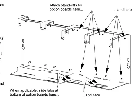
1. Attach four stand-offs to chassis as shown in Figure 3.4.
JCPU-3030D (with keypad/display) requires the longer stand-offs: 1.5 inch (38.1 mm); JCPU-3030ND (without keypad/display) requires the shorter stand-offs: 0.25 inch (6.35 mm) 2. Slide circuit-board tabs into slots on chassis as shown in Figure 3.4.
3. Place the board over the stand-offs so that mounting holes line up with those on the chassis. Secure all stand-offs with screws provided.
Layer 4 mounted to PEM studs and tab-slot
Layer 4 door-mounted* Layers 1&2&3 mounted to
PEM studs on chassis
Layers 1&2&3 mounted to PEM studs on chassis
Layers 1&2 mounted to PEM studs on chassis
Layers 1&2 mounted to PEM studs on chassis
Layer 4 mounted to PEM studs and tab-slot; Layer 3
suspended from Layer 4
Layer 4 mounted to PEM studs and tab-slot; Layer 3 suspended from Layer 4
CHS-M
3-opt
io
n
s.
cdr
*Note: If CHS-4N is used, door-mounting is only for use with ACM-24AT and ACM-48A series annunciators.
Figure 3.3 Configuring Equipment in Chassis (Side View): Positions 3 and 4 of CHS-M3, All 4 Positions of CHS-4N
NOTE: It is recommended that system design take into consideration the UL requirements for minimum separation of power-limited and non-power-limited wiring; for example, having all non-power-limited circuits grouped in one area of the cabinet (see Section 3.16 “UL Power-limited Wiring Requirements” and your power supply manual).
Attaching the CPU & Chassis Installation
Note for JCPU-3030D Due to the difficulty of reaching under the keypad, it may be convenient to remove the insulator from the lithium memory-backup battery at this time. See Section 3.5.1 “Memory-Backup Battery”.
Mounting Chassis in Backbox
Align chassis-mounting slots with chassis-mounting studs (see Figure 3.1 and Figure 3.4 for locations). Secure with nut & lock-washer provided with chassis.
3.5.1 Memory-Backup Battery
The lithium battery on the CPU provides backup of the CPU’s on-board memory during power loss. The CPU ships with an insulator to prevent the battery from discharging. To preserve the battery, the insulating tube should be left in place as long as possible before applying AC power.
If the insulator is not removed before applying AC power, the control panel will show a trouble situation.
This battery’s shelf-life should exceed 10 years, but if for some reason it fails, the control panel will show a trouble when powered up. To replace the lithium battery:
1. Make a full backup of all system settings to prevent loss of all programming data. 2. Disconnect all power sources.
3. JCPU-3030D only: Disconnect wiring and remove JCPU-3030D from backbox (3 screws at top, lift board tabs out of slot) and remove keypad (4 screws on back, LCD display stays attached).
!
CAUTION:It is critical that all mounting holes of the IFC-3030 are secured with a screw or stand-off to insurecontinuity of Earth Ground.
CPU standoffs at Positions 1 and 2: 1.5 inch (38.1 mm) for use with JCPU-3030D or 0.25 inch (6.35 mm) for use with JCPU-3030ND
CHS
-M3
.cdr
JCPU-3030ND (without keypad/display) JCPU-3030D (with keypad/display) Chassis-mounting slots
Figure 3.4 Standoffs on Chassis CHS-M3
Lift clip gently while
removing battery Dotted line indicates location of insulator
303
0-lit
hi
um
.c
Installation Attaching Option Boards
4. Remove battery from under clip (use fingers, because screwdriver could damage components) and insert new battery.
5. JCPU-3030D only: Replace keyboard, reinstall JCPU-3030D into chassis, and reconnect wiring.
6. Follow system power-up procedures.
7. Dispose of used battery promptly. Keep away from children. Do not disassemble and do not dispose of in fire.
3.6 Attaching Option Boards
If installing option boards into a CAB-4 Series backbox, mount & connect those boards at this time. This section contains general
instructions for mounting an option board; see the documentation that shipped with your board for any product-specific instructions.
As described in Section 3.4 “Laying Out
Equipment in Cabinet and Chassis”, up to eight option boards can be mounted in CHS-M3 to the right of the CPU; additional modules can be mounted in other chassis.
There are no slots in the first (back) two layers, but option boards with tabs (such as NCM-W) will still fit in those positions.
Mounting procedures
1. Install four 1 inch (25.4 mm) stand-offs onto the chassis as shown in Figure 3.5. 2. Place the first option board over the stand-offs so that holes line up.
3. If no more option boards will be mounted in that position, securely fasten all stand-offs with screws (provided with module). If mounting a second or third option board, attach another layer of stand-offs and repeat steps 2-3. Note: Set the switches on an option board before mounting another layer in front of it.
4. If mounting a pair of SLC loop modules, refer to Section 3.14.2 “Loop Control Module, Loop Expander Module” and to Section 3.7.3 “Installing a Multi-layer Module into the Chassis”.
!
CAUTION:The battery used in this device may present a risk of fire or chemical burn if mistreated.Do not recharge, disassemble, heat above 212°F (100°C), or incinerate. Replace battery with Notifier P/N LITHBATT-3V only. Use of another battery may present a risk of fire or explosion.
CHS
-M3
.cdr
Attach stand-offs for
option boards here... ...and here
Figure 3.5 Mounting Option Boards in CHS-M3
When applicable, slide tabs at
bottom of option boards here... ...and here
NOTE: Mounting two pairs of LCM-320 and LEM-320 modules in one chassis possition may cause intermittent electrical interference. If this occurs, move one pair to a separate chassis position.
Attaching Panel Circuit Modules Installation
5. For the top (fourth) layer of option boards, slide the tab at the bottom of the board into the slots on the chassis, and lay the board back onto the top of the chassis so that the studs line up with mounting holes on the option board. Securely fasten all stand-offs with screws provided with module.
6. If mounting the option board behind a blank module plate in a dress plate or annunciator backbox, see the BMP-1 Product Installation Drawing for details. This dress plate is suitable for option boards, which do not need to be visible or accessible when the door is closed.
7. If mounting a pair of loop control/expander modules, see Section 3.14.2 “Loop Control Module, Loop Expander Module”.
3.7 Attaching Panel Circuit Modules
3.7.1 Overview
If installing panel circuit modules into a CAB-4 Series backbox, mount and connect those boards at this time. This section contains general instructions for mounting a panel circuit module; see the sections about individual panel circuit modules for module-specific instructions. For voice alarm/ evacuation applications (VCM-4RK and DCM-4RK), see the Voice Alarm System Manual. • Mount an optional expander board to the module.
• Install the panel module onto a chassis. • Connect ribbon cables from CPU.
• Connect ICM-4RK and ICE-4 modules to the power supply.
• Connect NACs, IDCs, and relays; write any non-power-limited relay connections on door label.
• Field wire the module.
• After powering up the system, program the panel.
• Type your point-programming information onto the slide-in labels provided with your panel circuit module or create custom labels with LabelEase (available from Notifier); insert these labels into the slots at the top of the module.
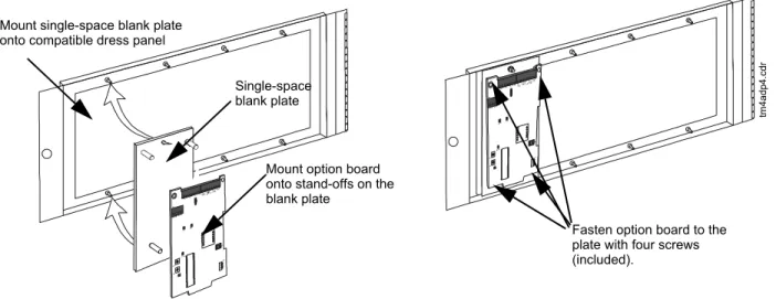
Single-space blank plate
Fasten option board to the plate with four screws (included).
tm
4a
dp
4.cd
r
Mount option board onto stand-offs on the blank plate
Mount single-space blank plate onto compatible dress panel
Note: Mounting instructions for option boards are the same in various dress panels.
Installation Attaching Panel Circuit Modules
3.7.2 Mount Expander Boards
Expander Board Modules need to be mounted onto their respective modules (e.g. ICE-4 onto ICM-4RK, or CRE-4 onto CRM-4RK) before being installed onto a chassis. To mount an expander module:
1. Remove one module support screw and set it aside for later use.
2. Replace the module support screw with one module stand-off (supplied with expander). 3. Repeat Steps 1 and 2 for the three remaining module support screws. Remove only one at a
time so the panel circuit module does not come apart.
4. Insert pins on the front of the expander board into connector on the back of the module. Make sure the pins are in line; then, press the two units together until they snap into place.
5. Install the four module support screws (removed earlier) through the back of the expander board and into the stand-offs. Tighten securely.
Figure 3.7 illustrates the steps.
3.7.3 Installing a Multi-layer Module into the Chassis
Follow the instructions illustrated in Figure 3.8 to install a panel circuit module or a pair of loop control/expander modules into into CHS-4N or CHS-M3.
1. Angle the module into the chassis so that the upper end of the rear board (or boards) fits into the top slot.
2. Bring the module back down so that the lower board edges slip into the bottom slots. 3. Secure the module to the chassis with the two module screws. Tighten securely. 4. Connect the ribbon cable to the module.
Install module stand-off Remove existing
module support screw
Plug in the expander board (front view shows pin connectors)
Secure with module support screws
3030
-pcmod
s.cdr
Steps 1 & 2:
Replace each screw with a standoff.
Note: Remove only one screw at a
time so that the panel circuit module does not come apart.
Steps 4 & 5
Connect and secure expander board.
Figure 3.7 Expander Module Installation
Attaching Panel Circuit Modules Installation
NOTE: Depending on system components, clearance may be tight. Do not force modules! Move the assembly around gently until you find the angle where components and mounting studs pass each other without scraping together.
voice
-mo
u
nt
-mo
d
.cd
r
Chassis
Module Screw Top
Slot
Bottom Slots
Installation Attaching Panel Circuit Modules
3.7.4 Connecting Expander Row Ribbon Cables
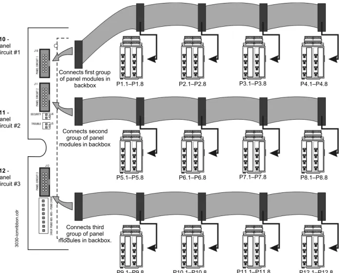
Expander Row Ribbon Cables connect panel circuit modules such as Indicating Circuit Modules (ICM-4RK) or Control Relay Modules (CRM-4RK) to the CPU.
Figure 3.9 provides a typical wiring setup connecting the control panel to three rows of panel circuit modules each below the CPU in a CAB-4 Series backbox.
P1.1–P1.8 J10 -
Panel Circuit #1
J12 - Panel Circuit #3
P2.1–P2.8 P3.1–P3.8 P4.1–P4.8
P5.1–P5.8 P6.1–P6.8 P7.1–P7.8 P8.1–P8.8
P9.1–P9.8 P10.1–P10.8 P11.1–P11.8 P12.1–P12.8
Expander Row Ribbon Cable (P/N 71088)
Connects first group of panel modules in
backbox
J11 - Panel Circuit #2
Connects second group of panel modules in backbox
Connects third group of panel modules in backbox.
30
30
-i
cm
ribb
on
.cdr
Initiating Device Circuits with IZM-8RK/IZE-A Installation
3.8 Initiating Device Circuits with IZM-8RK/IZE-A
3.8.1 Style B Field Wiring (Up to 8 Style B IDCs)
1. Initiating Device Circuits are supervised, power-limited and may be connected to
limited-energy cable. Initiating devices include non-coded manual pull station, heat detectors, photo and ion detectors, waterflow alarm and waterflow supervisory devices. Connect waterflow alarm devices to a dedicated circuit, programmed for waterflow option. Connect N.O. waterflow supervisory devices to a dedicated zone programmed for supervisory operation. The terminal blocks will accept 12AWG to 22AWG wire. Initiating circuit current will ensure alarming of one two-wire detector only.
2. Use only the compatible, UL/ULC-listed two-wire smoke detectors that are listed in the Device Compatibility Document.
3. For connection of 4-wire smoke detectors and initiating devices requiring separate 24 VDC power, refer to your power supply manual and to the wiring diagrams shipped with your devices.
4. Wire initiating devices according to the manufacturer's instructions packaged with each device.
5. For Canada, model N-ELR End-of-Line Resistor Assembly required. 6. Maximum line resistance due to wiring is 100 ohms.
4.7K, 1/2 watt ELR (71252)5
UL/ULC-listed two-wire smoke detector2
Manual Pull Station
Heat Detector
Dummy load all unused circuits with 4.7K ELR
(71245)
Typical NFPA Style B Initiating Device Circuit
!
WARNING:Do not mix fire alarm points with non-firealarm points on the same IZM-8RK/IZE-A Initiation Zone Module.
Installation Initiating Device Circuits with IZM-8RK/IZE-A
3.8.2 Style D Field Wiring
1. Initiating Device Circuits are supervised, power-limited and may be connected to
limited-energy cable. Initiating devices include non-coded manual pull station, heat detectors, photo and ion detectors, waterflow alarm and waterflow supervisory devices. Connect waterflow alarm devices to a dedicated circuit, programmed for waterflow option. Connect N.O. waterflow supervisory devices to a dedicated zone programmed for supervisory operation. The terminal blocks will accept 12AWG to 22AWG wire. Initiating circuit current will ensure alarming of one two-wire detector only.
2. Use only the compatible, UL/ULC-listed two-wire smoke detectors that are listed in the Device Compatibility Document.
3. For connection of 4-wire smoke detectors and initiating devices requiring separate 24 VDC power, refer to your power supply manual and to the wiring diagrams shipped with your devices.
4. Wire initiating devices according to the manufacturer's instructions packaged with each device.
5. Maximum line resistance due to wiring is 100 ohms.
UL/ULC-listed two-wire smoke detector. 2
Manual Pull Station
Heat Detector
Jumper all unused circuits
as shown
Typical NFPA Style D Initiating Device Circuit
!
WARNING:Do not mix fire alarm points with non-firealarm points on the same IZM-8RK/IZE-A Initiation Zone Module.
NACs with ICM-4RK⁄ICE-4 Installation
3.9 NACs with ICM-4RK
⁄
ICE-4
1. Notification circuits are supervised, power limited and may be connected to energy-limited cable.
2. Use only the compatible, UL-listed Notification Appliances listed in Device Compatibility Document.
3. Wire Notification Appliances according to the manufacturer's instructions packaged with each device.
4. Maximum current per circuit is 3.0 A. Maximum current per module depends on the type of power supply (standard or auxiliary).
5. Canadian installations require model N-ELR End-of-Line Resistor Assembly (Style Y only). 6. Size the NAC wiring so the voltage drop does not exceed the minimum rated voltage of the
notification appliance used as the last device on the circuit.
7. For zone coded applications, see the UZC-256 Universal Zone Coder manual. 8. For power wiring see Figure 3.14.
9. The ICM-4RK is California Code programmable (microprocessor P/N 34077 Rev. B or higher). To program for California Code, cut diode D35 as shown in Figure 3.13.
A B C D
A
B
C
D H
G E
F
INITIATING ZONE
RED = ALARM YELLOW = TROUBLE DISPLAY PROGRAM
INITIATING ZONE
RED = ALARM YELLOW = TROUBLE DISPLAY PROGRAM
b+ a+ a- b+ a+ a- b+ a+ a- b+ a+ a-
b-E F G H
b+ a+ a- b+ a+ a- b+ a+ a- b+ a+ a-
b-ICB
B+ A+ A– B– B+ A+ A– B– B+ A+ A– B– B+ A+ A– B–
Optional ICE-4 Indicating Circuit Expander.
Positions E, F, G, and H are active only with this board installed. Note that CRE-4 expander may also be installed on the ICM-4RK.
Jumpers for unused circuits
4.7K, 1/2 watt ELR5
P/N 71252
UL/ULC-listed 24 VDC Polarized
Devices
ICM
4wi
re
-St
yle
Y
Z
.c
d
r
Typical NFPA Style Y (Class B) Notification Appliance
Circuit
Jumpers for unused circuits Typical NFPA
Style Z (Class A) Notification Appliance
Circuit
Installation NACs with ICM-4RK⁄ICE-4
3.9.1 Power Supply Connections
Figure 3.14 illustrates typical connections from the main power supply. Figure 3.15 shows location of those connections on the bottom of the ICM-4RK and the ICE-4 modules.
Cut D35 on the circuit board to produce California code.
icm
-4
rk-d
3
5.
cdr
Figure 3.13 Location of D35 on ICM-4RK Circuit Board
J5
J6
J5
+5
V
1
A
MP GND GND ACCES
S
O
R
IE
S
T
B6
+2
4
V
1
A
MP
Power Cable P/N 71091 Power Harness (71093)
Black wire (–), Blue wire (+)
Note: Lugs must be removed and wires stripped
for connection to the power source.
30
30
-i
cmn
a
c.cd
r
Eight NACs that share up to 1 A. See note below.
AMPS-24/E
ICM-4RK
ICE-4
Figure 3.14 ICM-4RK/ICE-4 Main Power Supply Connection NOTE: For limitations on the total current available for any group of Notification Appliance Circuits (NACs), see Section 3.13 “Notification Appliance Circuit Current Limitations” on page 36, as well as the manual for your system’s power supply.
NOTE: ICM-4RK could be connected to a compatible UL/ULC-listed +24V auxiliary power supply instead (such as APS-6R). Refer to the manual for your auxiliary power supply for equivalent connections. If an auxiliary power supply is used, maximum current per circuit is 3 Amps, total output limited to the maximum rating of the supply.
!
b
WARNING:
Auxiliary power supply connections to ICM-4RK/ICE-4 must come from a power supply whose battery terminals are tied back to those on the main power supply. Failure to do so will cause panel circuit trouble at the control panel and possible equipment damage.