Copyright © 2015 Vilnius Gediminas Technical University (VGTU) Press Technika http://www.bjrbe.vgtu.lt
doi:10.3846/bjrbe.2015.15 OF ROAD AND BRIDGE ENGINEERING
ISSN 1822-427X / eISSN 1822-4288 2015 Volume 10(2): 118–125
1. Introduction
Suspension bridges are widely employed in long-span bridg-es since their internal force can be controlled well owing to the good energy-dissipating performance decided by its long period of the first-order longitudinal floating mode. Howev-er, the longitudinal displacement of the girders induced by vehicle braking forces, as one of the possible dynamic load-ings, may be excessive based on the following factors:
The number of vehicles running on a wide and long-span bridge is large. Pingsheng Bridge, as a case study in this paper, has a 350 m main span and twin decks, each of which carries a five-lane highway and is 19.70 m in width. Dynamic analysis for the Pingsheng Bridge induced by the vehicle braking force needs to be investigated.
For the separate twin-deck bridge, each deck serves one-way lane, so the braking forces of all the vehicles in each deck have the same direction. The accumulative ve-hicle braking force may be large enough to cause the lon-gitudinal vibration of the deck.
Vehicle braking time after being driven at a high speed is longer than at a low speed. Although the braking force is generally small compared with the bridge mass,
the dynamics response may still be excessive because of the longer braking time.
The excessive longitudinal displacements cause many problems such as bridge bearing damage, destruction of expansion joints, fatigue fracture of short hanger ca-bles, pounding between the girders and adjacent appro-ach bridges and so on. These problems certainly result in considerable difficulties in bridge maintenance, and even affect their normal operation. Therefore, it is very neces-sary to restrain the excessive longitudinal displacements. Some researches on seismic response control of the girder displacements for suspension bridges were investi-gated (Apaydin 2010; Yang et al. 2011, 2013), but the stu-dies on the longitudinal displacement mitigation of bridge girders subjected to braking force are quite few. Liu et al. (2010) and Qu et al. (2009) presented longitudinal vibra-tion response controls for a floating-type cable-stayed bridge induced by train braking forces.
Viscous dampers are commonly used for vibration control in civil engineering since it has the excellent cha-racteristics with damping energy dissipation, does not in-crease the stiffness of the structure, and does not restrain
A COMBINED CONTROL STRATEGY FOR VIBRATION MITIGATIONS
OF A SUSPENSION BRIDGE INDUCED BY VEHICLE BRAKING FORCE
Meng-Gang Yang1, Chun-Sheng Cai2, Biao Wei3
1, 3School of Civil Engineering, Central South University, No. 68 Shaoshan South Road, Changsha 410075, PR China 2Dept of Civil and Environmental Engineering, Louisiana State University, Baton Rouge, LA 70803, USA
E-mails: 1mgyang@csu.edu.cn; 2cscai@lsu.edu; 3weibiaocsu@163.com
Abstract. In order to mitigate the excessive longitudinal displacement responses of suspension bridge girders induced
by vehicle braking force, as one of the possible dynamic loadings, a combined control strategy consisting of viscous dampers and friction pendulum bearings is developed in this paper. Firstly, the vehicle composition and the braking force models of the Pingsheng Bridge are obtained by traffic survey and testing results, respectively. Then, the vibration response analysis for the bridge under the braking force is implemented using the MIDAS finite element model. Fur-thermore, viscous dampers and friction pendulum bearings are separately employed to reduce the vibration responses. The influence matrix method is first used to determine the optimal parameters of viscous dampers. Finally, the effect of the combined control strategy for the vibration control is investigated. The numerical analysis results indicate that uti-lizing the influence matrix method for the parameter optimization of viscous dampers is feasible and effective. It is also shown that the longitudinal displacement response of the Pingsheng Bridge subjected to the vehicle braking force can be effectively mitigated by viscous dampers, friction pendulum bearings or the combined control with the optimized parameters, and the combined control outperforms the viscous dampers or the friction pendulum bearings alone.
Keywords: suspension bridge, vehicle braking force, viscous damper, friction pendulum bearing, combined control,
the temperature deformation. Seismic protection and re-trofit of building structures can be achieved by viscous dampers (Hart et al. 2010; Hwang et al. 2007; Krishnamo-orthy 2011). Martinez-Rodrigo et al. (2010) presented the application of viscous dampers to mitigate the excessive resonant responses of railway bridges under high-speed moving loads, and Hwang and Tseng (2005) and Cheng et al. (2010) presented the vibration control techniques of viscous dampers for highway bridges and bridge cables. In addition, viscous dampers were investigated by Wang et al. (2005) to suppress the wind-induced vibrations of high-rise buildings and bridge cables. In these previous resear-ches, the design parameters of viscous dampers were de-termined by the method of trial and error. As a result, the calculating procedure is complicated and the obtained pa-rameters are not necessarily optimal. In this paper, a new application domain of viscous dampers for the vibration control under vehicle braking forces is developed, and the influence matrix method is first applied for the parameter optimization of viscous dampers.
Friction pendulum bearings (FPBs) belong to an effecti-ve friction-sliding isolated system, and haeffecti-ve self-return advantage. Vibration responses of the structure with FPBs can be mitigated since the vibration period is prolonged and the excitation energy is dissipated by the sliding friction. At present, the FPB is mainly applied for seismic response control of buildings and bridges (Ates et al. 2006; Jangid 2008; Panchal et al. 2009). A new attempt that the FPB is used to re-duce the vibration response of a suspension bridge subjected to vehicle braking forces will be investigated in this paper.
If the longitudinal displacements of the girders still exceed the limited value of the bridge bearings and the al-lowable value of the expansion joint when viscous dampers
and FPBs are separately used, a combined control strategy consisting of both viscous dampers and FPBs can be con-sidered.
The present study aims at developing a combined control strategy for vibration mitigations of a suspension bridge induced by vehicle braking forces. Firstly, the ve-hicle braking force models for the Pingsheng Bridge are obtained by traffic survey and testing results. Then, the MIDAS 3-D dynamic finite element model for the bridge is established, and the vibration response analysis is comple-ted under the braking force. Finally, the combined control strategy consisting of both viscous dampers and FPBs is developed to reduce the vibration responses in which the influence matrix method is first applied for the parameter optimization of viscous dampers, and the effectiveness of vibration mitigations is verified by numerical analysis. 2. Vehicle braking force acting on Pingsheng Bridge
2.1. Pingsheng Bridge
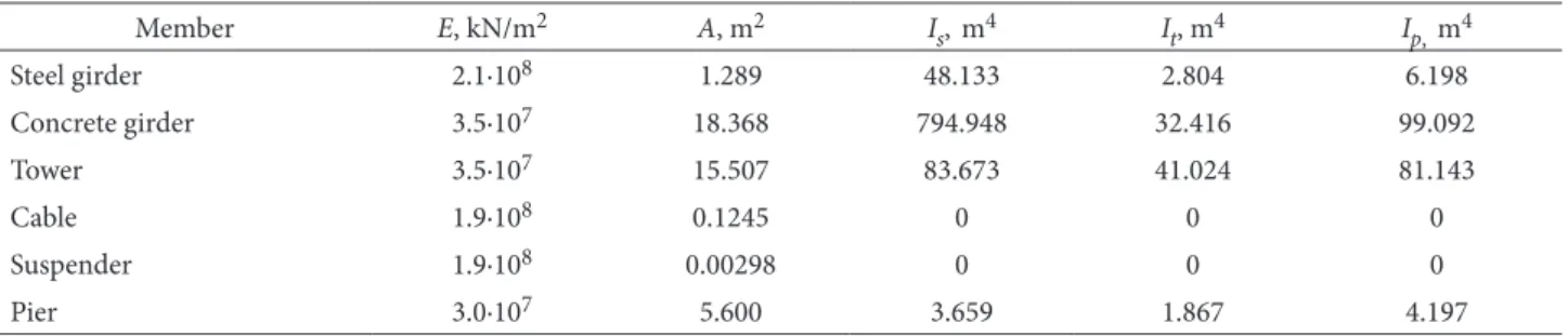
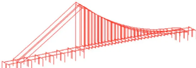
The Pingsheng Bridge is a self-anchored suspension bridge with a single tower in the Foshan city of Guangdong prov-ince, China. The general layout of the bridge is given in Fig. 1. The bridge has a main span of 350 m and is ranked the first among its kind. The tower of the bridge is made of concrete and is 143.38 m in height. The sag-to-span ratio for the steel main cables is 1/12.5 in the main span. The bridge has twin decks to carry a ten-lane highway, and each deck is 19.70 m in width and has five lanes. The girder of the main span is made of structural steel and that of the side span is made of concrete. The design vehicle speed is 80 km/h. Table 1 lists the main structural design param-eters of the Pingsheng Bridge.
Table 1. Main structural design parameters of the Pingsheng Bridge
Member E, kN/m2 A, m2 I
s, m4 It, m4 Ip, m4
Steel girder 2.1·108 1.289 48.133 2.804 6.198
Concrete girder 3.5·107 18.368 794.948 32.416 99.092
Tower 3.5·107 15.507 83.673 41.024 81.143
Cable 1.9·108 0.1245 0 0 0
Suspender 1.9·108 0.00298 0 0 0
Pier 3.0·107 5.600 3.659 1.867 4.197
2.2. Vehicle composition of Pingsheng Bridge
The vehicle types and their proportions in transportation are the two main factors in vehicle composition. Since dif-ferent road has difdif-ferent vehicle composition, the vehicle composition for a specific road should be obtained by traf-fic survey. It had been investigated by traftraf-fic management department that there were eight types of vehicles on the Guangfo highway linking Guangzhou city to Foshan city in China, as listed in Table 2. Since the Pingsheng Bridge is a connection between an urban road in the Foshan city and the Guangfo express highway, these data can be used in its dynamic analysis.
According to Table 2, small passenger cars have a high proportion in the vehicle composition, followed by me-dium-sized vehicles, large cars and towed vehicles. On the whole, this vehicle composition of the Guangfo highway is similar with that of other highways in China. In fact, some types of vehicles including minivan, passenger-car-go dual-purpose cars, minicars and light cars, have similar characteristics with small passenger cars in the number of axles and self-weight, and their proportions in the vehicle
composition are low. Therefore, minivans, passenger-car-go dual-purpose cars, minicars, light cars, and small pas-senger cars can be gathered and classified into light ve-hicles. Finally, the vehicle composition of the Pingsheng Bridge in this paper is simplified into four types, including light vehicles, medium-sized vehicles, large cars, and hea-vy vehicles. Their proportions in the vehicle composition are listed in Table 3. However, the proportion of the heavy vehicle is increasing according to the investigation of Can-tero et al. (2011), which will make the response induced by vehicle braking force larger.
2.3. Braking force model
The vehicle braking process includes four phases: (1) the re-sponse time of the brake system, about 0.015~0.03 s for a hy-draulic brake system and 0.05~0.06 s for a air brake system, respectively; (2) the action time of the brake, 0.15~0.3 s for a hydraulic brake system and 0.3~0.8 s for an air brake sys-tem, respectively, and the braking force gradually increases in this stage; (3) the continuous brake time, and the braking force is relatively stable in this stage; (4) the loose time of
Table 2. Taffic survey on Guangfo highway
No. Vehicle type Number of axles Proportion Note
1 Minivan 2 2.5
2 Passenger-cargo dual-purpose car 2 3.5
3 Minicar 2 3.3
4 Small passenger car 2 52.6
5 Light car 2 3.9 Carrying capacity: <2 tSeating capacity: <11
6 Medium-sized vehicle 2~3 14.9 Carrying capacity: 2 t ~7 tSeating capacity: 11~25
7 Large car 2~4 12.2 Carrying capacity: 7 t ~14 tSeating capacity: >25
8 Towed vehicle 4~5 7.1 Carrying capacity: >14 t
Table 3. Vehicle composition of the Pingsheng Bridge
Vehicle type Note Proportion, %
Light vehicle Including microvan, passenger-cargo dual-purpose car, minicar, small passenger car and light car 65.8
Medium-sized vehicle Definition see Table 2 14.9
Large car Definition see Table 2 12.2
Heavy vehicle i.e. towed vehicle 7.1
the brake system. The brake pedal is released by the driver in this stage and the braking process is over after this stage.
To obtain the braking force models, firstly the ave-rage gross weights of the four types of vehicles are obtai-ned from the statistical analysis by traffic management department. Then, the braking force test for them with the average gross weights was conducted at the velocity of 50 km/h by Peng and Wang (2003). Finally, according to the testing results and theoretical analysis, the complete vehicle braking ratios of the braking force to the vehicle gross weight and the braking force models are obtained. The vehicle braking force models are shown in Fig. 2. 3. Vibration response analysis
3.1. Finite element model
The dynamic 3-D MIADS finite element model of the Pingsheng Bridge is constructed and shown in Fig. 3. In this model, the bridge is discretized into 716 elements, in-cluding 448 beam elements, 108 truss elements and 160 ca-ble elements. The girder, tower and pier are modeled with spatial beam elements; the suspender is modeled with spa-tial truss elements; and the cable is modeled with two-node spatial catenary cable elements proposed by Yang et al. (2010). In the vibration response analysis, the effect of geo-metrical non-linearity under dead loads can be incorpo-rated by geometric stiffness matrixes of these elements. It has been known via static analysis that the foundations supporting the tower and the piers are quite stiff. Thus, the foundation deformations are not included in this model and the degrees of freedom associated with these nodes at the bottom of the tower and the piers are restrained. 3.2. Vehicle number for dynamic analysis
The total vehicle braking force acting on the Pingsheng Bridge is determined by the number and the braking force models of the vehicles. The braking force models have been discussed earlier. The vehicle number is related to the length of the bridge span, the lane number and the veloc-ity, besides the vehicle composition. Although the design vehicle speed is 80 km/h, the practical average velocity is about 50 km/h for urban road. The vehicle space is about 20 m based on the relationship between the car-following safe distance and the velocity investigated by Hoseini et al. (2009), which is essentially coincident with the data by an actual survey. Therefore, each lane can run 27 vehicles within the length of the bridge span, including 18 light ve-hicles, 4 medium-sized veve-hicles, 3 large cars, and 2 heavy vehicles according to the vehicle composition. The reduc-tion factor is 0.6 for five lanes of one deck by the Chinese code. Thus, the lane number after reduction is 3.0. There-fore, there are totally 81 vehicles on the bridge for dynamic analysis, including 54 light vehicles, 12 medium-sized ve-hicles, 9 large cars and 6 heavy vehicles.
3.3. Longitudinal displacement response
The longitudinal displacement response of the Pingsheng Bridge subjected to the braking force of 81 vehicles is
gained by finite element analysis (the uncontrolled curve in Fig. 4). The peak value of the longitudinal displacement of the girder reaches 37.7 cm, exceeding the limited value of 25 cm of the bridge bearings and the allowable value of 22 cm of the expansion joints excluding the displacement value under the action of the concrete shrinkage and creep, temperature and live load, which may lead to the destruc-tion of the bearings and the expansion joints. Therefore, the excess longitudinal displacements of the girders subjected to vehicle braking forces should be necessarily controlled. 4. Viscous damper for vibration mitigation
4.1. Mechanical model for viscous damper
The damper force of viscous dampers can be expressed as:
, (1)
where F – the damping force, kN; C – the viscous damping coefficient, kN·s/m; v – the relative velocity of the damper, m/s; α – the velocity exponent.
It is known from Eq (1) that the damping force is de-cided by the two parameters: the viscous damping coef-ficient C and the velocity exponent α. The damping force has a linear relationship with the viscous damping coef-ficient, yet is non-linear to the velocity exponent. In the application of civil engineering, C is usually in the range of 1000~10 000 kN·s/m, and α is in the range of 0.2~1.0. 4.2. Influence matrix method used in this study
The influence matrix method is an efficient and simple structural optimization method. To reduce the displace-ment response of the girders subjected to vehicle braking force, two viscous dampers are supposed to be installed in the longitudinal direction between the tower and the gird-er of the Pingsheng Bridge. According to Eq (1), the effect of vibration mitigation is determined by the two param-eters: C and α. In this study, the influence matrix method is applied to obtain the reasonable optimal design param-eters C and α of the dampers. The formula is as below:
, (2)
where [A] – the influence matrix; X and D – the passively controlled vector and the actively controlled vector, re-spectively.
The weight matrix [ρ] is used to consider the
impor-tance of different actively controlled element in the vector D, so Eq (2) can be re-written as following:
. (3)
In this study, the passively controlled elements in the vector X are the parameters C and α, and the active-ly controlled vector D is the control objective (i.e. the re-duction rate of key displacement or internal force). For the Pingsheng Bridge, the longitudinal displacement of the girder, the moment and the shear force at the bottom of the tower are the most important elements which need to be controlled subjected to vehicle braking forces. Therefo-re, the vectors X and D can be expressed as:
, , (4)
where C and α – the parameters of the viscous damper; S, M and Q – the reduction rates of the longitudinal displace-ment of the girder, the modisplace-ment, and the shear force at the bottom of the tower, respectively.
Since the element number in the passively controlled vector X is not equal to that in the actively controlled vec-tor D, the least square method is used to solve Eq (3). One can obtain:
. (5)
Therefore, the vector X can be solved from Eq (5)
. (6)
4.3. Parameter optimization
By finite element analysis for the Pingsheng Bridge with two viscous dampers, the influence matrix [A] is obtained as following:
. (7)
Considering that the mitigation of the longitudinal displacement of the girders is more important than that
of the internal force for the Pingsheng Bridge, the weight matrix [ρ] and the actively controlled vector D are set as:
, . (8)
In the vector D, every element in the vector is the res-ponse reduction rate β, which is defined as
, (9)
where e0 and e1 – the uncontrolled and controlled re-sponse, respectively.
Substituting Eqs (7)–(8) into Eq (6), the optimal pa-rameters C and α of the dampers can be determined as 2640 kN·s/m and 0.5, respectively.
Evidently, the influence matrix [A] is of vital im-portance in determining the optimal parameters of the dampers. Therefore, it must have a good stability. In theo-ry, the influence matrix method is only suitable for li-near system. Actually, high non-lili-nearity of suspension bridges mainly occurs in the construction process, while the non-linearity is not obvious during the service sta-ge, and its influence on seismic response for the bridge is less than 6% by the investigation of the first author. On the other hand, the non-linearity of the damper has little influence on the matrix [A] when the values of the parameters are in the range given in section 4.1. There-fore, the influence matrix method is feasible to be used for parameter optimizations of viscous dampers that are applied in vibration mitigations of the bridge subjected to vehicle braking forces.
4.4. Effect of vibration mitigation
On the basis of the optimal parameters C = 2640 kN·s/m and α = 0.5, the dynamic responses of the Pingsheng Bridge with viscous dampers subjected to vehicle braking forces are calculated. The results show that viscous dampers with optimal parameters not only reduce the longitudinal dis-placement obviously, but also decrease the internal forces at the bottom of the tower. Fig. 4 gives the comparison of the longitudinal displacement of the girders between the floating system (uncontrolled) and damped system (viscous damper). The maximum moment and shear force at the bot-tom of the tower are seen in Table 4. The peak value of the displacement, the maximum moment, and the maximum shear force decrease by 34.54%, 15.9% and 12.4%, respec-tively. In addition, the reduction rates obtained by finite el-ement analysis are close to the objective reduction rates in Eq (8), indicating that the influence matrix method is effec-tive to determine the optimal parameters of viscous damp-ers for vibration mitigations. The peak value of the displace-ment with viscous dampers is 24.68 cm that still exceeds the allowable value of 22 cm of the expansion joints.
5. Friction pendulum bearing (FPB) for vibration mitigation
5.1. FPB mechanical model
The damping force of FPBs is composed of the restoring force and the friction force, and can be expressed as:
, (10)
where W – the vertical reaction force, kN; R – the curva-ture radius of sliding surface, m; μ – the friction coefficient; x – the displacement, m; – the velocity, m/s; – the signum function.
The mechanical model has a non-linear characteritic, and can be simplified into a linear model which contains the equivalent stiffness and the equivalent damping ratio in the finite element analysis. The equivalent stiffness and the equivalent damping ratio are given as:
, . (11)
where Keff – the equivalent stiffness, kN/m; ξeff – the equivalent damping ratio; D – the design diaplacement of the bearing, m.
It can be seen from Eq (11) that the equivalent linear model is only determined by the two parameters R and m. Therefore, obtaining the optimized parameters is the first step for FPBs to be applied in vibration mitigations. 5.2. Analysis of FPB parameters
The friction coefficient m is related to the material of the in-terface and the sliding velocity. Teflon is a commonly-used material for the FPB interface, and its friction coefficient is in the range of 0.02~0.12. The stable friction coefficient is in the range of 0.06~0.12 when the sliding velocity exceeds a cer-tain value, and is in the range of 0.02~0.06 when the sliding velocity approaches to 0. Considering that the sliding veloc-ity of the bearing is low under the vehicle braking force, the range of friction coefficient m is chosen as 0.02~0.06.
The upper limit value of the curvature radius of the sliding surface R is determined by the self-return require-ment. The FPB cannot return to the original position if the restoring force is smaller than the friction force. Therefore, it is required: . If the design diaplacement D of the bearing is chosen as 25 cm, one has R < 2.5 m. On the other hand, the vertical displacement of the sliding surface in-creases with the decreasing curvature radius. Therefore, the lower limit value of the curvature radius R is determined by the restriction of the vertical displacement of the bearing. It is commonly required: R ≥ 0.5 m. As such, the reasonable range of the curvature radius is chosen as 0.5~2.0 m.
To obtain the optimum parameters for the prefera-ble performance in vibration mitigations, twenty cases are considered in the finite element analysis. In these cases,
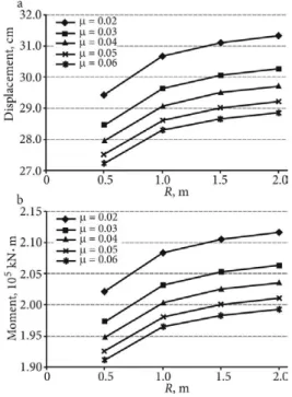
the friction coefficient m is set as 0.02, 0.03, 0.04, 0.05, and 0.06, and the curvature radius R is set as 0.5 m, 1.0 m, 1.5 m, and 2.0 m. For every pier of the Pingsheng Bridge, two bearings are supposed to be installed. The maximum displacement of the girder and the maximum moment at the bottom of the tower are shown in Fig. 5. The displace-ment and the modisplace-ment increase with the increasing curva-ture radius R, while decrease with the increasing friction coefficient μ. Therefore, it is obvious that the optimum pa-rameters R and μ are 0.5 m and 0.06, respectively.
5.3. Effect of vibration mitigation
On the basis of the optimum parameters R = 0.5 m and μ = 0.06, the dynamics responses of the Pingsheng Bridge with FPBs induced by the vehicle braking force are calcu-lated. The longitudinal displacement response of the girder is shown in Fig. 6. The peak value of the displacement is 27.06 cm and reduced by 28.22%. Also the maximum mo-ment and the shear force at the bottom of the tower are reduced by 14.6% and 12.5%, respectively (Table 4). There-fore, FPBs with the optimum parameters have good effects
Fig. 5. Variation of the key displacement and moment with R and μ: a – maximum displacement of the girder; b – maximum moment at the bottom of the tower
of vibration mitigations on suspension bridges. However, the peak value of the displacement with FPBs still exceeds the limited value of 25 cm of the bridge bearings and the allowable value of 22 cm of the expansion joints.
6. Combined control strategy
According to the foregoing investigation, it has been known that viscous dampers and FPBs can both reduce the longitudinal response of the bridge subjected to the ve-hicle braking force. To meet the need of the limited value of the bridge bearings and the allowable value of the ex-pansion joints, a control strategy combining viscous damp-ers and FPBs is put forward. In this strategy, the optimal parameters of viscous damper and FPB are adopted (i.e. C = 2640 kN·s/m, α = 0.5, R = 0.5 m and μ = 0.06), and the number and installed position of those are the same as stated above. By finite element analysis, the displacement response of the girder is shown in Fig. 6, and the maxi-mum moment and shear force at the bottom of the tower are given in Table 4. The peak value of the displacement, the maximum moment, and the maximum shear force are reduced by 42.17%, 23.5% and 19.4%, respectively. It has been verified by Fig. 6 and Table 4 that the combined con-trol performs better than an independent application of ei-ther viscous dampers or FPBs. The peak value of the dis-placement with a combined control is 21.8 cm, within the limited value of the bridge bearings and the allowable value of the expansion joints. The combined control strategy can meet the design requirement of the bridge bearings and the expansion joints induced by the vehicle braking force. 7. Conclusions
1. The paper has presented a combined control strategy consisting of viscous dampers and friction pendulum bearings, which has been developed to mitigate the exces-sive longitudinal displacement response of a suspension bridge induced by vehicle braking forces, as one of the pos-sible dynamic loadings.
2. Based on the vehicle braking force models obtai-ned by testing results and the MIDAS finite element mo-del, the vibration responses are analysed. The peak value of the longitudinal displacement responses of the Pingsheng Bridge reaches 37.7 cm, exceeding the limited value of the bridge bearings and the expansion joints. Therefore, it should be necessarily controlled.
3. The viscous dampers, the friction pendulum bea-rings and the combined control strategy are investigated in vibration control. The reduction rates of the longitudinal
displacement response achieved by viscous dampers, friction pendulum bearings, and the combined control with the opti-mized parameters are 34.54%, 28.22%, 42.17%, respectively, verifying the effectiveness of these control strategies for vi-bration mitigations of suspension bridges induced by vehicle braking forces. The combined control outperforms viscous dampers or friction pendulum bearings alone.
Acknowledgements
This work was supported by the grants (No. 51378504 and 51308549) from National Natural Science Foundation of China (NSFC), the project (No. IRT1287) from the depart-ment of education of China and the project (No. 13JJ7007) from Natural Science Foundation of Hunan Province, Chi-na. These supports are greatly appreciated.
References
Apaydin, N. M. 2010. Earthquake Performance Assessment and Retrofit Investigations of Two Suspension Bridges in Istanbul, Soil Dynamics and Earthquake Engineering 30(8): 702–710. http://dx.doi.org/10.1016/j.soildyn.2010.02.011
Ates, S.; Bayraktar, A.; Dumanoglu, A. A. 2006. The Effect of Spatially Varying Earthquake Ground Motions on The Sto-chastic Response of Bridges Isolated with Friction Pendulum Systems, Soil Dynamics and Earthquake Engineering 26(1): 31–44. http://dx.doi.org/10.1016/j.soildyn.2005.08.002 Cantero, D.; Gonzalez, A.; OBrien, E. J. 2011. Comparison of
Bridge Dynamic Amplifications due to Articulated 5-axle Trucks and Large Cranes, The Baltic Journal of Road and Bridge Engineering 6(1): 39–47.
http://dx.doi.org/10.3846/bjrbe.2011.06
Cheng, S. H.; Darivandi, N.; Ghrib, F. 2010. The Design of An Op-timal Viscous Damper for A Bridge Stay Cable Using Energy-based Approach, Journal of Sound and Vibration 329(22): 4689–4704. http://dx.doi.org/10.1016/j.jsv.2010.05.027 Hart, G. C.; Jain, A.; Ekwueme, C. G. 2010. Smart Buildings:
Vis-cous Dampers for A Tall Twisting Tower, Structural Design of Tall and Special Buildings 19(4): 373–396.
http://dx.doi.org/10.1002/tal.608
Hoseini, S. M. S.; Fathi, M.; Vaziri, M. 2009. Controlling Longitu-dinal Safe Distance between Vehicles, Promet-Traffic & Trans-portation 21(5): 303–310.
http://dx.doi.org/10.7307/ptt.v21i5.245
Hwang, J. S.; Wang, S. J.; Huang, Y. N.; Chen, J. F. 2007. A Seismic Retrofit Method by Connecting Viscous Dampers for Micro-electronics Factories, Earthquake Engineering and Structural Dynamics 36(11): 1461–1480.
http://dx.doi.org/10.1002/eqe.689
Table 4. The maximum moment and shear force at the bottom of the tower
Item Floating system (Uncontrolled) Damped system (Controlled)
Viscous damper FPB Combined
Moment Value (kN·m) 223 740 188 243 191 099 171 095
β – 15.9% 14.6% 23.5%
Shear force Value (kN) 1674 1466 1464 1349
Hwang, J. S.; Tseng, Y. S. 2005. Design Formulations for Supple-mental Viscous Dampers to Highway Bridges, Earthquake Engineering and Structural Dynamics 34(13): 1627–1642. http://dx.doi.org/10.1002/eqe.508
Jangid, R. S. 2008. Stochastic Response of Bridges Seismically Isolated by Friction Pendulum System, Journal of Bridge En-gineering 13(4): 319–330.
http://dx.doi.org/10.1061/(ASCE)1084-0702(2008)13:4(319) Krishnamoorthy, A. 2011. Variable Curvature Pendulum
Isola-tor and Viscous Fluid Damper for Seismic Isolation of Struc-tures, Journal of Vibration and Control 17(12): 1779–1790. http://dx.doi.org/10.1177/1077546310384640
Liu, J.; Qu, W. L.; Pi, Y. L. 2010. Active/Robust Control of Lon-gitudinal Vibration Response of Floating-Type Cable-Stayed Bridge Induced by Train Braking and Vertical Moving Loads, Journal of Vibration and Control 16(6): 801–825.
http://dx.doi.org/10.1177/1077546309106527
Martinez-Rodrigo, M. D.; Lavado, J.; Museros, P. 2010. Dynamic Performance of Existing High-Speed Railway Bridges Under Resonant Conditions Retrofitted with Fluid Viscous Damp-ers, Engineering Structures 32(3): 808–828.
http://dx.doi.org/10.1016/j.engstruct.2009.12.008
Panchal, V. R.; Jangid, R. S. 2009. Seismic Response of Structures with Variable Friction Pendulum System, Journal of Earth-quake Engineering 13(2): 193–216.
http://dx.doi.org/10.1080/13632460802597786
Peng, Y. H.; Wang, L. M. 2003. A Study on The Simulation of Ve-hicle’s Braking Process, Journal of Fuzhou University (Natural Science) 31(2): 182–185 (in Chinese).
Qu, W. L.; Qin, S. Q.; Tu, J. W.; Liu, J.; Zhou, Q.; Cheng H.; Pi, Y. L. 2009. Intelligent Control for Braking-induced Longitu-dinal Vibration Responses of Floating-Type Railway Bridges, Smart Materials and Structures 18(12): 125003.
http://dx.doi.org/10.1088/0964-1726/18/12/125003
Wang, X. Y.; Ni, Y. Q.; Ko, J. M.; Chen, Z. Q. 2005. Optimal De-sign of Viscous Dampers for Multi-Mode Vibration Con-trol of Bridge Cables, Engineering Structures 27(5): 792–800. http://dx.doi.org/10.1016/j.engstruct.2004.12.013
Yang, M. G.; Li, C. Y.; Chen, Z. Q. 2013. A New Simple Non-linear Hysteretic Model for MR Damper and Verification of Seismic Response Reduction Experiment, Engineering Structures 52: 434–445. http://dx.doi.org/10.1016/j.engstruct.2013.03.006 Yang, M. G.; Chen, Z. Q.; Hua, X.G. 2011. An Experimental
Study on Using MR Damper to Mitigate Longitudinal Seis-mic Response of A Suspension Bridge, Soil Dynamics and Earthquake Engineering 31(8): 1171–1181.
http://dx.doi.org/10.1016/j.soildyn.2011.04.006
Yang, M. G.; Chen, Z. Q.; Hua, X. G. 2010. A New Two-Node Catenary Cable Element for The Geometrically Non-linear Analysis of Cable-Supported Structures, Proceedings of the In-stitution of Mechanical Engineers, Part C: Journal of Mechani-cal Engineering Science 224(C6): 1173–1183.
http://dx.doi.org/10.1243/09544062JMES1816