AND BRIDGE ENGINEERING 2020/1 5(1) ISSN 1822-427X/eISSN 1822-4288
2020 Volume 15 Issue 1: 1–25 https://doi.org/10.7250/bjrbe.2020-15.459
DAMAGE DETECTION OF TRUSS STRUCTURES
BY REDUCTION OF DEGREES OF FREEDOM
USING THE SEREP METHOD
SHAHIN LALE AREFI, AMIN GHOLIZAD*
Dept of Civil Engineering, University of Mohaghegh Ardabili, Ardabil, Iran
Received 20 March 2019; accepted 30 July 2019
Abstract. Damage detection of bridge structures during their operating lifetime is essential. In this paper, two approaches, All Degrees of Freedom and Reduction of the Degrees of Freedom methods, are used to detect the damages in structures. The first method considers All Degrees of Freedom of the structure and the second method, Reduction of the Degrees of Freedom. Since the sensors are installed only on a few degrees of freedom, the responses are available for some of them. The Degrees of Freedom must be reduced and System Equivalent Reduction Expansion Process method is one of the most efficient ways to solve the problem. This research aimed to identify the damage of structures using the Modal Strain Energy method by reducing the structural degree of freedom. Two standard examples are used and the results compared to different damage cases to examine the efficiency of the mentioned method. The results illustrated the proper performance of the Reduction of the Degrees of Freedom method to identify the damage in truss structures. By increasing the number of modes, Reduction of the Degrees of Freedom method detects
* Corresponding author. E-mail: [email protected]
Shahin LALE AREFI (ORCID ID 0000-0002-3595-1303) Amin GHOLIZAD (ORCID ID 0000-0002-0827-8854)
Copyright © 2020 The Author(s). Published by RTU Press
2020/1 5(1)
considerably more accurate the damaged elements, especially when the noise is considered. Also, based on the outcomes to identify damaged elements, it is possible to consider more modes instead of more sensors.
Keywords: bridge health monitoring, damage detection, degrees of freedom, Modal Strain Energy (MSE) model, reduction method, noise level, System Equivalent Reduction Expansion Process (SEREP) method, truss structures.
Introduction
Structural health monitoring and damage detection of structures have been a matter of constant interest. Many structures, especially truss bridges, are faced with failure in their lifetime. Trusses with a bridge-type geometry are one of the most important and most practical structures, which use in civil engineering. Bridge structures have a vital role in urban development infrastructures (Zavadskas, Kaklauskas, Peldschus, & Turskis, 2007). Determining the damage to structures is especially important at early stages, to prevent the destruction of structures, their collapse and the increase in the cost of the structure.
One of the components of a smart structure is the structural health monitoring of bridge structures, which lead to the reduction of costs of repair and retention (Bitarafan, Zolfani, Lale Arefi, & Zavadskas, 2014).
Damage in structures is initially in the form of local damage, which may occur in structural elements, but over time, damages may lead to the collapse of the structure. So, with proper identification of damaged elements in the structure and repairing them, it is possible to increase the useful life of the structure considerably. It is also feasible to detect the damaged elements and make a plan to repair them to prevent further damage. Therefore, identifying the magnitude and location of damage in the structures is very important.
The purpose of damage identification is to obtain the damage in a structure from the measured responses of the structures (Kourehli, 2017). The change in physical characteristics of structures, such as reduction of stiffness leads to a change in frequencies, mode shapes, and damping of the structure (Chang, Flatau, & Liu, 2003).
Amin Gholizad
Damage Detection of Truss Structures by Reduction of Degrees of Freedom Using the Serep Method
energy for model updating, and some researches have been studied this topic (Liu, Li, H., Li, W., & Wang, 2014; Yan Ren, & Huang, 2012).
The main idea of the using Modal Strain Energy technique in damage identification was presented by Stubbs, Kim, & Topole (1992). Shi,Law, & Zhang(2000) used the MSE technique in their research to determine the location of structural damage. Finally, results showed that the use of modal strain energy has proper performance.
Mottershead & Friswell in 1993, investigated finite element model updating techniques using vibration measurements. In all reduction methods, there is a relation between the master degrees of freedom and slave degrees of freedom (Friswell & Mottershead, 1995). Finite element model updating has been applied successfully in many fields.
Jaishi & Ren (2005, 2006) used either the single-objective or multi-objective optimisation method to update the finite element models of civil engineering structures in structural dynamics using the strain energy residual.
Hu, Li, & Wang (2007) developed a model updating technique called Cross Model Cross Mode (CMCM). They showed the CMCM model updating method is capable of updating the stiffness, mass and damping matrices simultaneously.
Jaishi & Ren (2007) applied a multi-objective optimisation method, using model updating to adjust eigenvalue and strain energy residuals. Esfandiari, Bakhtiari-Nejad, Rahai, & Sanayei (2009) presented a structural model updating using a least-square algorithm with appropriate normalisation method. They illustrated that the proposed technique could identify the severity and location of damage in trusses.
Hu & Wu (2009) expanded the damage index to identify damage in plates based on the Modal Strain Energy (MSE) method. In this method, the damage index is introduced as MSE before and after damage for all measured modes. Deng & Cai (2010) applied a model updating method to update a concrete bridge based on the response surface method and a genetic algorithm. Ribeiro Calçada, Delgado, Brehm, & Zabel (2012) described the calibration of the numerical model of a bowstring-arch railway bridge based on modal parameters identified from an ambient vibration test using modal strain energy residuals in objective function and a genetic algorithm optimisation algorithm.
2020/1 5(1)
offshore structures. To show the efficiency of their technique, they applied it to different cases in marine structures. Finally, the obtained results illustrated the efficiency of the method in damage identification of structures. Ashory, Ghasemi-Ghalebahman, & Kokabi (2018) obtained damage in plates with laminated composite using efficient MSE. The outcomes demonstrate that the damage identification using the MSE method in composite plates has acceptable results and ultimately, the accuracy of the method is improved in comparison to the other methods.
This study uses the model updating method named as System Equivalent Reduction Expansion Process (SEREP) method and MSE method to extend the previously mentioned researches involved in the model updating of bridge structures. The System Equivalent Reduction Expansion Process method is one of the reduction techniques, which intend to discuss in this study by locating the damage of structures via the MSE technique. In the next sections, the principles of the SEREP method and the MSE method are presented. Finally, using two different samples, the efficiency and accuracy of the mentioned method are investigated.
1.
System Equivalent Reduction Expansion Process
(SEREP)
The System Equivalent Reduction Expansion Process (SEREP) method firstly presented by O’Callahan, Avitabile, & Riemer (1989) to reduce the model analysis system. In this method, the total degrees of freedom (DOFs) of the whole structure is divided into masters and slaves DOFs. Only master DOFs are considered in dynamic analysis. Hence, by a transmission matrix; the slave DOF responses are obtained utilising the responses from the master DOFs and, these approximate responses will be used in the analysis process.
The Eq. of eigenvalue-problem for the structure without damping can be written as:
K n2 M n 0 n=1,…,ndf (1)
where the K is the structural stiffness matrix, M is the structural mass
matrix, ωn is the frequency of a structure, φn is the mode shape of the
structure and ndf is the number of total degrees of freedom of the structure.
Amin Gholizad
Damage Detection of Truss Structures by Reduction of Degrees of Freedom Using the Serep Method
K K K K
M M
M M
mm ms
sm ss i
2 mm ms
sm ss
m
s
0 , (2)
where the symbols m are the master coordinates, and the symbols s are the slave coordinates (O’Callahan, Avitabile, & Riemer, 1989).
The response of a structure can be a linear combination of the mode shapes. The modal transformation equations can be written as:
x
xms xn n , (3)
where {xn} is a response of a structure and [φn] is a vector of mode
shapes. In Eq. (3), {q} illustrates the contribution of each mode in the response of the system. Hence, for the master degrees of freedoms:
{xm} = [φm]{q}. (4)
Pre-multiplying both sides of the Eq. (4) by [φm]T gives:
[φm]T{xm} = [φm]T[φm]{q}. (5)
Pre-multiplying both sides of the Eq. (5) by ([φm]T[φm])-1 gives:
([φm]T[φm])-1[φm]T{xm} = ([φm]T[φm])-1[φm]T[φm]{q}. (6)
Eq. (6) can be written as (O’Callahan, Avitabile, & Riemer, 1989):
q m x
T
m m
T m
1
m g
(7)
{q} = [φm]g{xm}. (8)
The superscript “g” refers to pseudo-inverse.
xn n m g x
T
m
SEREP
(9)
In this method, TSEREP matrix, which defined as the transformation
matrix, will be as follows (O’Callahan, Avitabile, & Riemer, 1989):
[TSEREP] = [φn]([φm]T[φm])-1[φm]T. (10)
It is possible to obtain a response in slave degrees of freedom by transformation matrix using the responses at the master degrees of freedom (Qu, 2004). In the SEREP method, the reduced model will exactly reproduce the mode shapes in considering without noise (Friswell & Mottershead, 1995)
2020/1 5(1)
2. Modal Strain Energy (MSE) method
The Modal Strain Energy (MSE) method is one of the most widely used and powerful methods for identifying structural damage. Hence, the MSE method is utilised in this paper to locate the structural damage by reducing the degrees of freedom in structures. The damage increases the MSE index of the damaged element in a structure.
The strain energy of the structure derived from the vector of mode shape is called MSE. The MSE in element e and mode i of the structure (mseie) can be defined as follows:
mseie 21 re Ti ke ire i 1 ndf e 1 nte, (11)
where ke is the stiffness matrix of element e of the structure, mse k i ndf e nte
ie 12 ire T is the e ire 1 1
corresponding vector of the nodal deformations of the reduced model in mode i, nte is the total number of elements.
n ir m
s
,i 1, ,nm, (12)
where nm is the number of modes, φm is themaster degrees of freedom
and φs is the slave degrees of freedom, which obtained from SEREP
method. By normalising the modal strain energy of eth elements (nmse ier)) concerning the total modal strain energy of the structure:
nmse mse
mse
ier
ie
e nte
ie
1
�
,i 1, ,nm, (13)
where r- the related parameter obtained from the reduced model.
For the mode nm an effective parameter (mnmseer) can be selected as follows:
mnmse nmse
nm e nte
e
r i
nm ie
1 , 1 ,, , (14)
where
mnmse nmse
nm e nte
e r i
nm ie
1 is the normalised MSE of the elements , 1 ,, e in the mode i.
Finally, by determining the effective (mnmsee) parameter, each
healthy and damaged element of the structure is specified mnmsee r h
as and mnmsee rd. A useful index can be defined for predicting the location of damages in the structure. The obtained index is called the reduced Modal Strain Energy Based Index (MSEBIre) and can be specified as follows (Shi,Law, & Zhang, 1998):
MSEBI max mnmse mnmse
mnmse e
re
e r
d e
r h
e r h
Amin Gholizad
Damage Detection of Truss Structures by Reduction of Degrees of Freedom Using the Serep Method
where mnmsee rd and mnmsee rh are the mean of strain energy in the element. Under Eq. (15), those elements, which are healthy the equivalent index is zero. Also, those elements, which the damage had occurred in them the equivalent index is above zero.
3. Numerical example
Two reference examples have been considered to investigate the two methods described in this paper. The first studied sample is a planar steel truss with 15-element and the second sample is a planar truss with 31 elements. For both samples, three different damage cases are considered. Also, the MSE index is applied to obtain the location of the damage. Additionally, to evaluate the effect of the mode number in damage detection of truss bridge structures, two numbers of modes are considered in each case.
3.1. Planar truss, 15-element truss
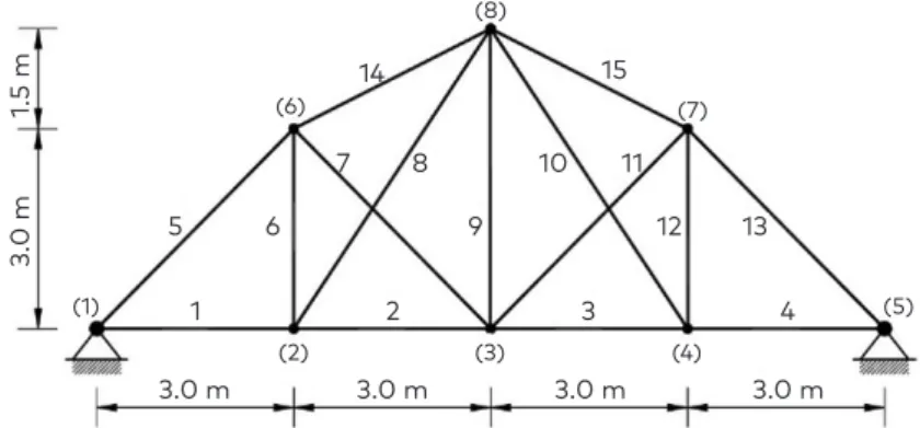
A planar steel truss presented in Gomes & Silva (2008), as shown in Figure 1, is used. The total number of elements in this truss is 15. Since each node of the truss has two degrees of freedom, its total degree of freedom is 12. The area of cross-section and mass per unit length are equal to 0.005 m2 and 39.25 kg/m for vertical members, and 0.010 m2
and 78.5 kg/m for top and bottom horizontal members and 0.008 m2 and
62.8 kg/m for diagonal members, respectively. Moreover, the modulus of elasticity of the truss members is 200 GPa, and its density is 7850 kg/m3.
Three different damage cases have been used to identify the structural damage in the structure by reducing the degrees of freedom
Figure 1. The 15-element planar steel truss 14
(8)
(6)
(1)
(7)
(5)
(2) (3) (4)
7 8
9
10 11
15
12 13
3 4
2 1
6 5
3.0 m
3.
0 m
1.5 m
2020/1 5(1)
of the structure in this truss bridge. In Table 1, three damage cases are shown for the steel truss bridge with 15 elements.
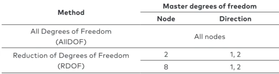
In this paper, two methods have been applied to investigate the methods of reduction degrees of freedom in the identification of structural damage by MSEBI. The first method considers all degrees of freedom of the structure. Therefore the response is available at All Degrees of Freedom (AllDOF). In the second method, Reduction of the Degrees of Freedom (RDOF) is done by SEREP method. The number of master degrees of freedom considered for this truss bridge in the RDOF method is 4. In this way, the master degrees of freedom are determined at nodes 2 and 8, and then modal analysis of each method is performed.
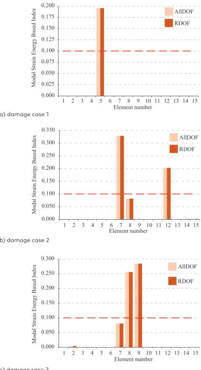
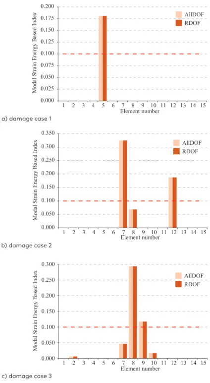
Different values of the MSEBI for three damage cases without noise are shown in Figure 2. The first 3 modes are used in this case to obtain MSEBI values. Pursuant to Figure 2, both AllDOF and RDOF methods have a similar performance. It can be observed that the damaged location is correctly determined in all damage cases. In damage case 1, the damage of element 5 is correctly detected. In damage case 2, the damage of element 7 and 12, and, in damage case 3, the damage of elements 8 and 9 are correctly detected without any false. Also, the RDOF method has yielded an appropriate performance even with decreasing degrees of freedom and has been able to perform the same function as the AllDOF method.
Table 1. Different damage cases for a 15-element truss
Damage ratio Element number
Damage cases
0.15 5
Case 1
0.15 7
Case 2
0.10 12
0.15 8
Case 3
0.15 9
Table 2. Master degrees of freedom for a 15-element truss
Master degrees of freedom Method
Direction Node
All nodes All Degrees of Freedom
(AllDOF)
1, 2 2
Reduction of Degrees of Freedom
Amin Gholizad
Damage Detection of Truss Structures by Reduction of Degrees of Freedom Using the Serep Method
a) damage case 1
b) damage case 2
c) damage case 3
Figure 2. Damage index values in 15-element truss for three modes without noise
0.000 0.025 0.050 0.075 0.100 0.125 0.150 0.175 0.200
1 2 3 4 5 6 7 8 9 10 11 12 13 14 15
Modal Strain Ener
gy
Based Inde
x
Element number
AllDOF RDOF
0.000 0.050 0.100 0.150 0.200 0.250 0.300 0.350
1 2 3 4 5 6 7 8 9 10 11 12 13 14 15
Modal Strain Ener
gy
Based Inde
x
Element number
AllDOF RDOF
Modal Strain Ener
gy
Based Inde
x
0.000 0.050 0.100 0.150 0.200 0.250 0.300
1 2 3 4 5 6 7 8 9 10 11 12 13 14 15 Element number
AllDOF
2020/1 5(1)
Moreover, to consider the noise effect in the numerical example, a ±3% noise level is used in all damage cases for the mode shapes (Dinh-Cong, Vo-Duy, Ho-Huu, Dang-Trung, & Nguyen-Thoi, 2017).
in
i n i
1 (16)
in which is theith mode shape with considering the noise level, is ith mode shape without noise, n is the noise level (±3%, in this paper) and is a random value between [-1; 1] (Aydin & Kisi, 2015).
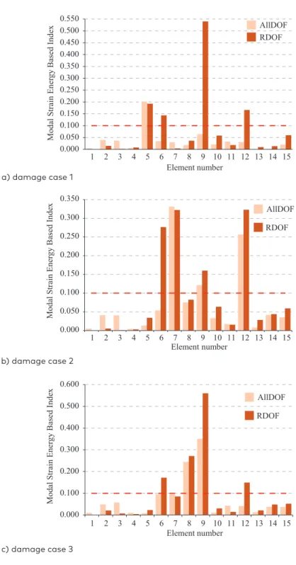
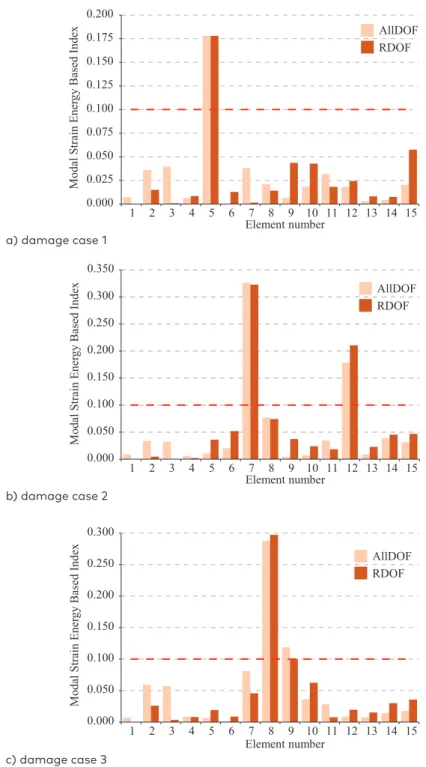
In this truss bridge, a 3% noise is used to analyse its effect on the mode shapes. The results of the MSEBI values for the three damage cases for the first 3 modes are shown in Figure 3. Pursuant to Figure 3, it is seen that whereas the AllDOF method can successfully locate the damaged element in all damage cases with only one false element (element 9 in damage case 2). However, the RDOF method has only some false elements in three damage cases (elements 6, 9 and 12 in damage case 1, elements 6 and 9 in damage case 2, elements 6 and 12 in damage case 3). The reason is that in the AllDOF method, it is assumed that sensors exist in all degrees of freedom means the response is available in all of them. Therefore, it has a good performance than RDOF method in locating the damaged element of structures. Moreover, the RDOF method, even with the reduction of degrees of freedom, has been desirable to identify the damage of the truss bridge structure.
Different values of the MSEBI for the three damage cases without noise for the first 4 modes are shown in Figure 4. Pursuant to Figure 4, the damage location is correctly detected in all damage cases. So, in case 1, the damaged element 5 is correctly detected. In damage case 2, the damaged elements 7 and 12, and in the case 3, the damaged elements 8 and 9 are correctly detected without the false. In other words, the RDOF method has yielded proper performance even with decreasing degrees of freedom and has been able to perform similarly to the AllDOF method.
Amin Gholizad
Damage Detection of Truss Structures by Reduction of Degrees of Freedom Using the Serep Method
a) damage case 1
b) damage case 2
c) damage case 3
Figure 3. Damage index values in 15-element truss for three modes
with 3% noise
AllDOF RDOF 0.000 0.050 0.100 0.150 0.200 0.250 0.300 0.350 0.400 0.450 0.500 0.550
1 2 3 4 5 6 7 8 9 10 11 12 13 14 15
Modal Strain Ener
gy Based Inde x Element number 0.000 0.050 0.100 0.150 0.200 0.250 0.300 0.350
1 2 3 4 5 6 7 8 9 10 11 12 13 14 15
Modal Strain Ener
gy Based Inde
x
Element number
AllDOF RDOF
Modal Strain Ener
gy Based Inde
x 0.000 0.100 0.200 0.300 0.400 0.500 0.600
1 2 3 4 5 6 7 8 9 10 11 12 13 14 15 Element number AllDOF RDOF AllDOF RDOF 0.000 0.050 0.100 0.150 0.200 0.250 0.300 0.350 0.400 0.450 0.500 0.550
1 2 3 4 5 6 7 8 9 10 11 12 13 14 15
Modal Strain Ener
gy Based Inde x Element number 0.000 0.050 0.100 0.150 0.200 0.250 0.300 0.350
1 2 3 4 5 6 7 8 9 10 11 12 13 14 15
Modal Strain Ener
gy Based Inde
x
Element number
AllDOF RDOF
Modal Strain Ener
gy Based Inde
x 0.000 0.100 0.200 0.300 0.400 0.500 0.600
1 2 3 4 5 6 7 8 9 10 11 12 13 14 15 Element number
2020/1 5(1)
a) damage case 1
b) damage case 2
c) damage case 3
Figure 4. Damage index values in 15-element truss for four modes without
noise 0.000 0.025 0.050 0.075 0.100 0.125 0.150 0.175 0.200
1 2 3 4 5 6 7 8 9 10 11 12 13 14 15
Modal Strain Ener
gy Based Inde
x Element number AllDOF RDOF AllDOF RDOF 0.000 0.050 0.100 0.150 0.200 0.250 0.300 0.350
1 2 3 4 5 6 7 8 9 10 11 12 13 14 15 Element number
Modal Strain Ener
gy Based Inde
x 0.000 0.050 0.100 0.150 0.200 0.250 0.300
1 2 3 4 5 6 7 8 9 10 11 12 13 14 15
Modal Strain Ener
gy Based Inde
x Element number AllDOF RDOF 0.000 0.025 0.050 0.075 0.100 0.125 0.150 0.175 0.200
1 2 3 4 5 6 7 8 9 10 11 12 13 14 15
Modal Strain Ener
gy Based Inde
x Element number AllDOF RDOF AllDOF RDOF 0.000 0.050 0.100 0.150 0.200 0.250 0.300 0.350
1 2 3 4 5 6 7 8 9 10 11 12 13 14 15 Element number
Modal Strain Ener
gy Based Inde
x 0.000 0.050 0.100 0.150 0.200 0.250 0.300
1 2 3 4 5 6 7 8 9 10 11 12 13 14 15
Modal Strain Ener
gy Based Inde
x Element number AllDOF RDOF 0.000 0.025 0.050 0.075 0.100 0.125 0.150
1 2 3 4 5 6 7 8 9 10 11 12 13 14 15
Modal Strain Ener
gy Based Inde
Element number AllDOF RDOF 0.000 0.050 0.100 0.150 0.200 0.250 0.300 0.350
1 2 3 4 5 6 7 8 9 10 11 12 13 14 15 Element number
Modal Strain Ener
gy Based Inde
x 0.000 0.050 0.100 0.150 0.200 0.250 0.300
1 2 3 4 5 6 7 8 9 10 11 12 13 14 15
Modal Strain Ener
gy Based Inde
x
Element number
Amin Gholizad
Damage Detection of Truss Structures by Reduction of Degrees of Freedom Using the Serep Method
Figure 5. Damage index values in 15-element truss for four modes
with 3% noise a) damage case 1
b) damage case 2
c) damage case 3
0.000 0.025 0.050 0.075 0.100 0.125 0.150 0.175 0.200
1 2 3 4 5 6 7 8 9 10 11 12 13 14 15
Modal Strain Ener
gy Based Inde x Element number AllDOF RDOF 0.000 0.050 0.100 0.150 0.200 0.250 0.300 0.350
1 2 3 4 5 6 7 8 9 10 11 12 13 14 15
Modal Strain Ener
gy Based Inde x Element number AllDOF RDOF 0.000 0.050 0.100 0.150 0.200 0.250 0.300
1 2 3 4 5 6 7 8 9 10 11 12 13 14 15
Modal Strain Ener
gy Based Inde x Element number AllDOF RDOF 0.000 0.025 0.050 0.075 0.100 0.125 0.150 0.175 0.200
1 2 3 4 5 6 7 8 9 10 11 12 13 14 15
Modal Strain Ener
gy Based Inde x Element number AllDOF RDOF 0.000 0.050 0.100 0.150 0.200 0.250 0.300 0.350
1 2 3 4 5 6 7 8 9 10 11 12 13 14 15
Modal Strain Ener
gy Based Inde x Element number AllDOF RDOF 0.000 0.050 0.100 0.150 0.200 0.250 0.300
1 2 3 4 5 6 7 8 9 10 11 12 13 14 15
Modal Strain Ener
2020/1 5(1)
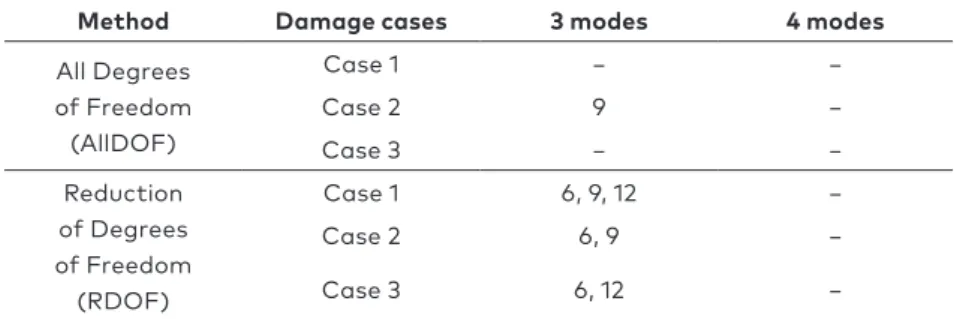
Table 3 shows false elements for 15-element truss without noise and with considering 3% noise, respectively. The elements whose MSEBI indices exceed 0.10 in the structure are selected as damaged structural elements. It observed from Tables 3 that by increasing the number of modes, the RDOF method with limited sensors had high accuracy in damage identification of the elements.
3.2. Planar truss, 31-element truss
The first example used in this article to examine the efficiency of these methods is 31-element truss bridge. The 31-element truss bridge is used for evaluating the methods, as shown in Figure 6 (Messina, Williams, & Contursi, 1998). The modulus of elasticity of the truss element is 70 GPa, and its density of the material is 2770 kg/m3. The
cross-sectional area of members is 0.004 m2. Generally, this truss has
31 members and 14 nodes. The number of degrees of freedom of this structure is 25. The modulus of elasticity reduction has been used to consider the effects of damage in this structure.
Table 3. False elements identified for the 15-element truss with considering 3% noise
Method Damage cases 3 modes 4 modes
All Degrees of Freedom
(AllDOF)
Case 1 − −
Case 2 9 −
Case 3 − −
Reduction of Degrees of Freedom (RDOF)
Case 1 6, 9, 12 −
Case 2 6, 9 −
Case 3 6, 12 −
Amin Gholizad
Damage Detection of Truss Structures by Reduction of Degrees of Freedom Using the Serep Method
Three different damaged cases are considered to detect the damage in this structure. Table 4 shows different types of damage cases in the truss with 31 elements.
Table 5 presents the location of the master degrees of freedom, which are considered as the location of the sensors. Accordingly, only six sensors are utilised at nodes 1, 3, 4, 9, 10 and 12, which are regarded as the master degrees of freedom.
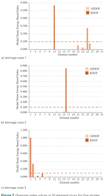
Figure 7 indicates different values of the MSEBI without noise for the three damage cases and the first five modes. The elements whose MSEBI indices exceed 0.10 in the structure are selected as damaged structural elements. Based on the results of Figure 7, the damage location is correctly determined in all cases in conditions without noise. So in case 1, the elements 11 and 25 are correctly detected without the false. In damage case 2, the damage of element 16 is correctly detected. In damage case 3, the damages of elements 1 and 2 are correctly detected, and the element 6 is falsely detected as the damaged element. In other words, the RDOF method has been the proper performance even with
Table 4. Different damage cases for a 31-element truss
Damage ratio Element number
Damage cases
0.25 11
Case 1
0.15 25
0.30 16
Case 2
0.30 1
Case 3
0.20 2
Table 5. Master degrees of freedom for a 31-element truss
Master degrees of freedom Method
Direction Node
All nodes All Degrees of Freedom (AllDOF)
1, 2 1
Reduction of Degrees of Freedom (RDOF)
1, 2 3
2 4
1, 2 9
2 10
2020/1 5(1)
a) damage case 1
b) damage case 2
c) damage case 3
Figure 7. Damage index values in 31-element truss for five modes without noise 0.000 0.100 0.200 0.300 0.400 0.500 0.600
1 3 5 7 9 11 13 15 17 19 21 23 25 27 29 31
Modal Strain Ener
gy Based Inde
x Element number AllDOF RDOF 0.000 0.100 0.200 0.300 0.400 0.500 0.600 0.700 0.800 0.900
1 3 5 7 9 11 13 15 17 19 21 23 25 27 29 31
Modal Strain Ener
gy Based Inde x Element number AllDOF RDOF 0.000 0.200 0.400 0.600 0.800 1.000 1.200
1 3 5 7 9 11 13 15 17 19 21 23 25 27 29 31
Modal Strain Ener
gy Based Inde x Element number AllDOF RDOF 0.000 0.100 0.200 0.300 0.400 0.500 0.600
1 3 5 7 9 11 13 15 17 19 21 23 25 27 29 31
Modal Strain Ener
gy Based Inde
x Element number AllDOF RDOF 0.000 0.100 0.200 0.300 0.400 0.500 0.600 0.700 0.800 0.900
1 3 5 7 9 11 13 15 17 19 21 23 25 27 29 31
Modal Strain Ener
gy Based Inde x Element number AllDOF RDOF 0.000 0.200 0.400 0.600 0.800 1.000 1.200
1 3 5 7 9 11 13 15 17 19 21 23 25 27 29 31
Modal Strain Ener
gy Based Inde x Element number AllDOF RDOF 0.000 0.100 0.200 0.300 0.400 0.500
1 3 5 7 9 11 13 15 17 19 21 23 25 27 29 31
Modal Strain Ener
gy Based Inde
x Element number AllDOF RDOF 0.000 0.100 0.200 0.300 0.400 0.500 0.600 0.700 0.800 0.900
1 3 5 7 9 11 13 15 17 19 21 23 25 27 29 31
Modal Strain Ener
gy Based Inde x Element number AllDOF RDOF 0.000 0.200 0.400 0.600 0.800 1.000 1.200
1 3 5 7 9 11 13 15 17 19 21 23 25 27 29 31
Modal Strain Ener
Amin Gholizad
Damage Detection of Truss Structures by Reduction of Degrees of Freedom Using the Serep Method
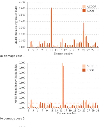
Figure 8. Damage index values in 31-element truss for five modes with 3% noise
a) damage case 1
b) damage case 2
c) damage case 3
0.000 0.100 0.200 0.300 0.400 0.500 0.600 0.700
Modal Strain Ener
gy Based Inde x Element number AllDOF RDOF 0.000 0.100 0.200 0.300 0.400 0.500 0.600 0.700 0.800 0.900
1 3 5 7 9 11 13 15 17 19 21 23 25 27 29 31
Modal Strain Ener
gy Based Inde
x Element number AllDOF RDOF 0.000 0.200 0.400 0.600 0.800 1.000 1.200
1 3 5 7 9 11 13 15 17 19 21 23 25 27 29 31
Modal Strain Ener
gy Based Inde
x
Element number
AllDOF RDOF 1 3 5 7 9 11 13 15 17 19 21 23 25 27 29 31 0.000 0.100 0.200 0.300 0.400 0.500 0.600 0.700
Modal Strain Ener
gy Based Inde x Element number AllDOF RDOF 0.000 0.100 0.200 0.300 0.400 0.500 0.600 0.700 0.800 0.900
1 3 5 7 9 11 13 15 17 19 21 23 25 27 29 31
Modal Strain Ener
gy Based Inde
x Element number AllDOF RDOF 0.000 0.200 0.400 0.600 0.800 1.000 1.200
1 3 5 7 9 11 13 15 17 19 21 23 25 27 29 31
Modal Strain Ener
gy Based Inde
x
Element number
2020/1 5(1)
decreasing degrees of freedom, and able to perform the same function as the AllDOF method.
The results of the MSEBI values for the three damage cases are shown for the first five modes in Figure 8. As reported by the results obtained from Figure 8, it is clear that the RDOF method can be correctly detected the damage location with a few false. In damage case 1 for the AllDOF method, elements 11 and 25 are correctly detected as the damaged element and the elements 16, 21 and 26 are falsely detected as the damaged one. In the RDOF method, elements 11 and 25 are correctly detected as the damaged element and the elements 21 and 26 are falsely detected as the damaged one. In damage case 2 for the AllDOF methods, element 16 is correctly detected, and the elements 11 and 26 are falsely detected as the damaged element. For the RDOF method, the element 16 is correctly detected, and the elements 2, 6, 25, 26 and 30 are falsely detected as the damaged element.
Also, in damage case 3, for the AllDOF method the elements 1 and 2 are correctly detected, and the elements 6, 11, 16 and 26 are falsely detected as the damaged element with the very low index value. For the RDOF method, the elements 1 and 2 are correctly detected, and the elements 6, 8, 9, 11, 25 and 26 are falsely detected as the damaged element. Therefore, the RDOF method, even with the reduction of degrees of freedom, has been desirable and has been able to detect the damage of the structure compared to the AllDOF method.
To investigate the effects of the number of modes in this paper, in addition to considering 5 modes, the 7 modes are also used to obtain structural damage detection.
Different values of the MSEBI are shown in Figure 9 for three damage cases without noise for the first 7 modes. Pursuant to Figure 9, the damage location is correctly determined in conditions of without noise, in all damage cases. Accordingly, for both methods, in damage case 1, the elements 11 and 25 are correctly detected without any false. In damage case 2, for the AllDOF method, element 16 is correctly detected without any false. For the RDOF method, element 16 is correctly identified, but the element 6 is falsely identified as a damaged element. In damage case 3 for both methods, elements 1 and 2 are correctly identified with only one false damaged element (element 6). These results indicate that the accuracy of the RDOF method has risen by increasing the number of modes to 7. Hence, the RDOF method, even with the reduction of degrees of freedom, has been very desirable in comparison to the AllDOF method.
Amin Gholizad
Damage Detection of Truss Structures by Reduction of Degrees of Freedom Using the Serep Method
Figure 9. Damage index values in 31-element truss for seven modes without noise
a) damage case 1
b) damage case 2
c) damage case 3
0.000 0.100 0.200 0.300 0.400 0.500 0.600 0.700 0.800 0.900
1 3 5 7 9 11 13 15 17 19 21 23 25 27 29 31
Modal Strain Ener
gy Based Inde x Element number AllDOF RDOF 0.000 0.100 0.200 0.300 0.400 0.500 0.600 0.700 0.800 0.900
1 3 5 7 9 11 13 15 17 19 21 23 25 27 29 31
Modal Strain Ener
gy Based Inde x Element number AllDOF RDOF 0.000 0.200 0.400 0.600 0.800 1.000 1.200
1 3 5 7 9 11 13 15 17 19 21 23 25 27 29 31
Modal Strain Ener
gy Based Inde x Element number AllDOF RDOF 0.000 0.100 0.200 0.300 0.400 0.500 0.600 0.700 0.800 0.900
1 3 5 7 9 11 13 15 17 19 21 23 25 27 29 31
Modal Strain Ener
gy Based Inde x Element number AllDOF RDOF 0.000 0.100 0.200 0.300 0.400 0.500 0.600 0.700 0.800 0.900
1 3 5 7 9 11 13 15 17 19 21 23 25 27 29 31
Modal Strain Ener
gy Based Inde x Element number AllDOF RDOF 0.000 0.200 0.400 0.600 0.800 1.000 1.200
1 3 5 7 9 11 13 15 17 19 21 23 25 27 29 31
Modal Strain Ener
gy Based Inde x Element number AllDOF RDOF 0.000 0.100 0.200 0.300 0.400 0.500 0.600 0.700 0.800
1 3 5 7 9 11 13 15 17 19 21 23 25 27 29 31
Modal Strain Ener
gy Based Inde x Element number AllDOF RDOF 0.000 0.100 0.200 0.300 0.400 0.500 0.600 0.700 0.800 0.900
1 3 5 7 9 11 13 15 17 19 21 23 25 27 29 31
Modal Strain Ener
gy Based Inde x Element number AllDOF RDOF 0.000 0.200 0.400 0.600 0.800 1.000 1.200
1 3 5 7 9 11 13 15 17 19 21 23 25 27 29 31
Modal Strain Ener
2020/1 5(1)
Figure 10. Damage index values in 31-element truss for seven modes
with 3% noise a) damage case 1
b) damage case 2
c) damage case 3
0.000 0.100 0.200 0.300 0.400 0.500 0.600 0.700 0.800 0.900
1 3 5 7 9 11 13 15 17 19 21 23 25 27 29 31
Modal Strain Ener
gy Based Inde x Element number AllDOF RDOF 0.000 0.100 0.200 0.300 0.400 0.500 0.600 0.700 0.800 0.900
1 3 5 7 9 11 13 15 17 19 21 23 25 27 29 31
Modal Strain Ener
gy Based Inde x Element number AllDOF RDOF 0.000 0.200 0.400 0.600 0.800 1.000 1.200
1 3 5 7 9 11 13 15 17 19 21 23 25 27 29 31
Modal Strain Ener
gy Based Inde x Element number AllDOF RDOF 0.000 0.100 0.200 0.300 0.400 0.500 0.600 0.700 0.800 0.900
1 3 5 7 9 11 13 15 17 19 21 23 25 27 29 31
Modal Strain Ener
gy Based Inde x Element number AllDOF RDOF 0.000 0.100 0.200 0.300 0.400 0.500 0.600 0.700 0.800 0.900
1 3 5 7 9 11 13 15 17 19 21 23 25 27 29 31
Modal Strain Ener
gy Based Inde x Element number AllDOF RDOF 0.000 0.200 0.400 0.600 0.800 1.000 1.200
1 3 5 7 9 11 13 15 17 19 21 23 25 27 29 31
Modal Strain Ener
gy Based Inde x Element number AllDOF RDOF 0.000 0.100 0.200 0.300 0.400 0.500 0.600 0.700 0.800
1 3 5 7 9 11 13 15 17 19 21 23 25 27 29 31
Modal Strain Ener
gy Based Inde x Element number AllDOF RDOF 0.000 0.100 0.200 0.300 0.400 0.500 0.600 0.700 0.800 0.900
1 3 5 7 9 11 13 15 17 19 21 23 25 27 29 31
Modal Strain Ener
gy Based Inde x Element number AllDOF RDOF 0.000 0.200 0.400 0.600 0.800 1.000 1.200
1 3 5 7 9 11 13 15 17 19 21 23 25 27 29 31
Modal Strain Ener
Amin Gholizad
Damage Detection of Truss Structures by Reduction of Degrees of Freedom Using the Serep Method
reported by the results obtained in Figure 10, in case 1, both methods are correctly determined actual site of damage (elements 11 and 25). In case 2, the elements 11 and 25 are correctly detected without any false. In damage case 2 for the AllDOF method, element 16 is correctly detected without any false. For the RDOF method, element 16 is correctly identified, but the element 6 is falsely identified as the damaged element. In damage case 3 for the AllDOF method, elements 1 and 2 are correctly identified with only two false damaged elements (elements 6 and 16). Also, for the RDOF method, elements 1 and 2 are correctly identified with only one false damaged element (element 6). It observed that the result of the RDOF method has been very desirable by increasing the number of modes to 7.
Table 6 and Table 7 show false elements for the 31-element truss without considering noise and with considering 3% noise, respectively. It is seen that by increasing the number of modes, the RDOF method with limited sensors had high accuracy in damage identification of the elements.
Table 6. False elements identified for the 31-element truss without noise
Method Damage cases 5 modes 7 modes
All Degrees of Freedom
(AllDOF)
Case 1 − −
Case 2 − −
Case 3 6 6
Reduction of Degrees of Freedom (RDOF)
Case 1 − −
Case 2 − −
Case 3 6 6
Table 7. False elements identified for the 31-element truss with considering 3% noise
Method Damage cases 5 modes 7 modes
All Degrees of Freedom (AllDOF)
Case 1 16, 21, 26 −
Case 2 11, 26 −
Case 3 6, 11, 16, 26 6, 16
Reduction of Degrees of Freedom
(RDOF)
Case 1 21, 26 −
Case 2 2, 6, 25, 26, 30 6
2020/1 5(1)
Conclusions
Determining the damage to truss bridge structures is especially important at early stages, to prevent the destruction of structures, their collapse and the increase in the cost of the structure. Practically, the response is available at some structural degrees of freedom. Due to the installation of sensors at some degrees of freedom, responses exist only in limited degrees of freedom for the sensor. The purpose of this paper is to identify damages in truss bridge structures using the Modal Strain Energy Based Index method by reducing the structural degrees of freedom. Two methods are investigated once with sensors at all degrees of freedom and once with sensors at some degrees of freedom compared to the results. In this regard, two standard examples are utilised to evaluate the effectiveness of the two methods described in this paper. A 3% noise is also used for the mode shapes to study the noise effects. Also, two modes are used in each sample to evaluate the effect of the number of modes on the damage identification of truss bridge structures. The following conclusions were drawn:
1. The results illustrated that for the 15-element truss and considering 3 modes, the All Degrees of Freedom method had a better performance than the Reduction of Degrees of Freedom method in identifying the damaged elements.
2. By increasing the number of modes to 4, the Reduction of Degrees of Freedom method has been very satisfactory in identifying damaged elements.
3. The results showed that the reduction of the model to 31-element truss was desirable, and only a few false elements were observed. 4. By increasing the number of modes to 7, the Reduction of Degrees
of Freedom method was able to identify more accurately the damaged elements.
5. It is beneficial to model updating method to identify the damage location in structures using System Equivalent Reduction Expansion Process method.
Amin Gholizad
Damage Detection of Truss Structures by Reduction of Degrees of Freedom Using the Serep Method
REFERENCES
Ashory, M. R., Ghasemi-Ghalebahman, A., & Kokabi, M. J. (2018). An efficient modal strain energy-based damage detection for laminated composite plates. Advanced Composite Materials, 27(2), 147-162.
http://doi.org/10.1080/09243046.2017.1301069
Aydin, K., & Kisi, O. (2015). Damage diagnosis in beam-like structures by artificial neural networks. Journal of Civil Engineering and Management,
21(5), 591-604. http://doi.org/10.3846/13923730.2014.890663
Bitarafan, M., Zolfani, S. H., Lale Arefi, S. H., & Zavadskas, E. K. (2014). Evaluation of real-time intelligent sensors for structural health monitoring of bridges based on SWARA-WASPAS; a case in Iran. Baltic Journal of Road & Bridge Engineering 9(14): 333-340. https://doi.org/10.3846/bjrbe.2014.40
Chang, P. C, Flatau, A, & Liu, S. C. (2003). Review paper: Health monitoring of civil infrastructure. Structural Health Monitoring Journal 2(3): 257-267. https://doi.org/10.1177/1475921703036169
Chen, H. P., & Bicanic, N. (2006). Inverse damage prediction in structures using nonlinear dynamic perturbation theory. Computational Mechanics, 37(5), 455-467. https://doi.org/10.1007/s00466-005-0717-y
Deng, L., & Cai, C. S. (2010). Bridge model updating using response surface method and genetic algorithm. Journal of Bridge Engineering 15(5): 553–564. https://doi.org/10.1061/(ASCE)BE.1943-5592.0000092
Dinh-Cong, D., Vo-Duy, T., Ho-Huu, V., Dang-Trung, H., & Nguyen-Thoi, T. (2017). An efficient multi-stage optimization approach for damage detection in plate structures. Advances in Engineering Software, 112, 76-87.
https://doi.org/10.1016/j.advengsoft.2017.06.015
Esfandiari, A. (2014). Structural model updating using incomplete transfer function of strain data. Journal of Sound and Vibration, 333(16), 3657-3670. https://doi.org/10.1016/j.jsv.2014.03.015
Esfandiari, A., Bakhtiari-Nejad, F., Rahai, A., & Sanayei, M. (2009). Structural model updating using frequency response function and quasi-linear sensitivity equation. Journal of sound and vibration, 326(3-5), 557-573. https://doi.org/10.1016/j.jsv.2009.07.001
Friswell, M., & Mottershead, J. E. (1995). Finite element model updating in structural dynamics (Vol. 38). Springer Science & Business Media.
https://doi.org/10.1007/978-94-015-8508-8
Gomes, H. M., & Silva, N. R. S. (2008). Some comparisons for damage detection on structures using genetic algorithms and modal sensitivity method. Applied Mathematical Modelling, 32(11), 2216-2232.
https://doi.org/10.1016/j.apm.2007.07.002
Hu, H., & Wu, C. (2009). Development of scanning damage index for the damage detection of plate structures using modal strain energy method. Mechanical Systems and Signal Processing, 23(2), 274-287.
https://doi.org/10.1016/j.ymssp.2008.05.001
2020/1 5(1)
Jaishi, B., & Ren, W. X. (2005). Structural finite element model updating using ambient vibration test results. Journal of structural engineering, 131(4), 617-628. https://doi.org/10.1061/(ASCE)0733-9445(2005)131:4(617) Jaishi, B., & Ren, W. X. (2006). Damage detection by finite element model
updating using modal flexibility residual. Journal of sound and vibration,
290(1-2), 369-387. https://doi.org/10.1016/j.jsv.2005.04.006
Jaishi, B., & Ren, W. X. (2007). Finite element model updating based on eigenvalue and strain energy residuals using multiobjective optimisation technique. Mechanical systems and signal processing, 21(5), 2295-2317. https://doi.org/10.1016/j.ymssp.2006.09.008
Kourehli, S. S. (2017). Damage Diagnosis of Structures Using Modal Data and Static Response. Periodica Polytechnica Civil Engineering, 61(1), 135-145. https://doi.org/10.3311/PPci.7646
Li, Y., Wang, S., Zhang, M., & Zheng, C. (2016). An improved modal strain energy method for damage detection in offshore platform structures. Journal of Marine Science and Application, 15(2), 182-192.
https://doi.org/10.1007/s11804-016-1350-1
Liu, F., Li, H., Li, W., & Wang, B. (2014). Experimental study of improved modal strain energy method for damage localisation in jacket-type offshore wind turbines. Renewable Energy, 72, 174-181.
https://doi.org/10.1016/j.renene.2014.07.007
Messina, A., Williams, E. J., & Contursi, T. (1998). Structural damage detection by a sensitivity and statistical-based method. Journal of sound and vibration,
216(5), 791-808. https://doi.org/10.1006/jsvi.1998.1728
Mottershead, J. E., & Friswell, M. I. (1993). Model updating in structural dynamics: a survey. Journal of sound and vibration, 167(2), 347-375.
https://doi.org/10.1006/jsvi.1993.1340
O’Callahan, J. C., Avitabile, P., & Riemer. R. (1989). System equivalent reduction expansion process. In Proc. of the 7th International Modal Analysis Conference, 1989.
Qu, Z. Q. (2004). Model order reduction techniques with applications in finite element analysis. Springer Science & Business Media.
https://doi.org/10.1007/978-1-4471-3827-3
Ribeiro, D., Calçada, R., Delgado, R., Brehm, M., & Zabel, V. (2012). Finite element model updating of a bowstring-arch railway bridge based on experimental modal parameters. Engineering Structures, 40, 413-435.
https://doi.org/10.1016/j.engstruct.2012.03.013
Shan, D., Li, Q., Khan, I., & Zhou, X. (2015). A novel finite element model updating method based on substructure and response surface model. Engineering Structures, 103, 147-156. https://doi.org/10.1016/j.engstruct.2015.09.006 Shi, Z., Law, S. S., & Zhang, L. (2000). Structural damage detection from modal
strain energy change. Journal of engineering mechanics, 126(12), 1216-1223. https://doi.org/10.1061/(ASCE)0733-9399(2000)126:12(1216)
Amin Gholizad
Damage Detection of Truss Structures by Reduction of Degrees of Freedom Using the Serep Method
Stubbs, N., Kim, J. T., & Topole, K. (1992, April). An efficient and robust algorithm for damage localization in offshore platforms. In Proc. of the ASCE 10th Structures Congress (Vol. 1, pp. 543-546).
Yan, W. J., Ren, W. X., & Huang, T. L. (2012). Statistic structural damage detection based on the closed-form of element modal strain energy sensitivity.
Mechanical Systems and Signal Processing, 28, 183-194. https://doi.org/10.1016/j.ymssp.2011.04.011