Copyright © 2018 The Author(s). Published by RTU Press
This is an Open Access article distributed under the terms of the Creative Commons Attribution License (http://creativecommons.org/licenses/by/4.0/), which permits unre-stricted use, distribution, and reproduction in any medium, provided the original author and source are credited.
*Corresponding author. E-mail: [email protected]
https://doi.org/10.7250/bjrbe.2018-13.407
Introduction
The modern roundabout is a circular intersection, suc-cessfully implemented worldwide over the past few dec-ades. However, roundabout design guidance criteria are nonuniform. Some studies have extensively reviewed sev-eral International design practices, guidelines, and regula-tions, potentially leading to improved local standards able to meet the needs of modern roads.
An international review of roundabout design stan-dards and guidelines was undertaken by Kennedy (2007) to support the revision of the United Kingdom (UK) Stan-dard for Roundabouts. A design hierarchy for roundabouts was proposed depending on road types, speed limits on the approach roads (greater or lower than 65 km/h) and on the vehicular and non-motorised user flows. A “compact” roundabout was also proposed for low-volume roads, with one lane entries, exits, and circulatory carriageway.
The review of the International standards and guide-lines carried out by (Montella, Turner, Chiaradonna, & Al-dridge, 2013) showed that the combined effect produced by different roundabout geometric elements on safety performance is more important than each single impact. Furthermore, several inconsistencies in the Italian stan-dard have been identified (the absence of splitter island design, the number of exit lanes limited to 1, the unfea-sible planning of roundabouts on divided highways); and recommendations for improvement have been proposed. The authors suggested the performance-based geometric design as the best approach, by better calibrating safety performance functions by means of additional geometric design parameters.
Pilko (2017) and Bezina, Stančerić, and Ahac (2017) conducted an International literature review on round-about geometric design and traffic efficiency practices,
INVESTIGATING THE DEVIATION ANGLE METHOD
FOR ENSURING DEFLECTION AT ONE-LANE RURAL ROUNDABOUTS
Nicola BERLOCO*, Pasquale COLONNA, Paolo INTINI, Vittorio RANIERI
Dept of Civil, Environmental, Building Engineering and Chemistry, Technical University of Bari, Bari, Italy
Received 02 August 2017; accepted 16 January 2018
Abstract. Roundabouts developed as a road intersection design option has resulted in a series of nonuniform design guid-ance criteria in Europe, as well as in the United States and other Countries. In addition to different design specifications about the geometry of the elements constituting a roundabout (width and lanes of the circulatory roadway, entry and exit legs, splitter island), the methods for guaranteeing that vehicle paths deflect through the roundabout are also different. These methods ensure proper travel speeds between conflicting traffic flows. Currently, the main parameters used by stand-ards to control the deflection are the deflection radius, the entry path radius, and the deviation angle.
After a comparison between International deflection methods for roundabouts, this study checks the geometric require-ments of the deviation angle for more than 7.000 hypothetical one-lane rural roundabouts. The Computer-Aided Design (CAD) drawing of the roundabouts takes into account the range of variability of their main geometric parameters, accord-ing to the Italian Standard. Subsequently, a number of the considered roundabouts checked with both the entry path radius and the German methods. Some results showing the greater effectiveness of the less popular deviation angle method are discussed. The main aims of this paper are:
1) to promote the deviation angle method, which is only used in Switzerland and Italy; 2) to improve standards, as regards the applicability and validity of the deflection angle method;
3) to help practitioners to know in advance the outcome of the deflection checks at the beginning of the iterative design process, once the boundary conditions are known.
mainly focused on capacity and delay, to introduce and improve the Croatian guidelines. The indication of the best models and simulation software to be used for ana-lysing and improving operational features of roundabouts was the most important goal of this comprehensive and systematic field-analytical study on existing roundabouts.
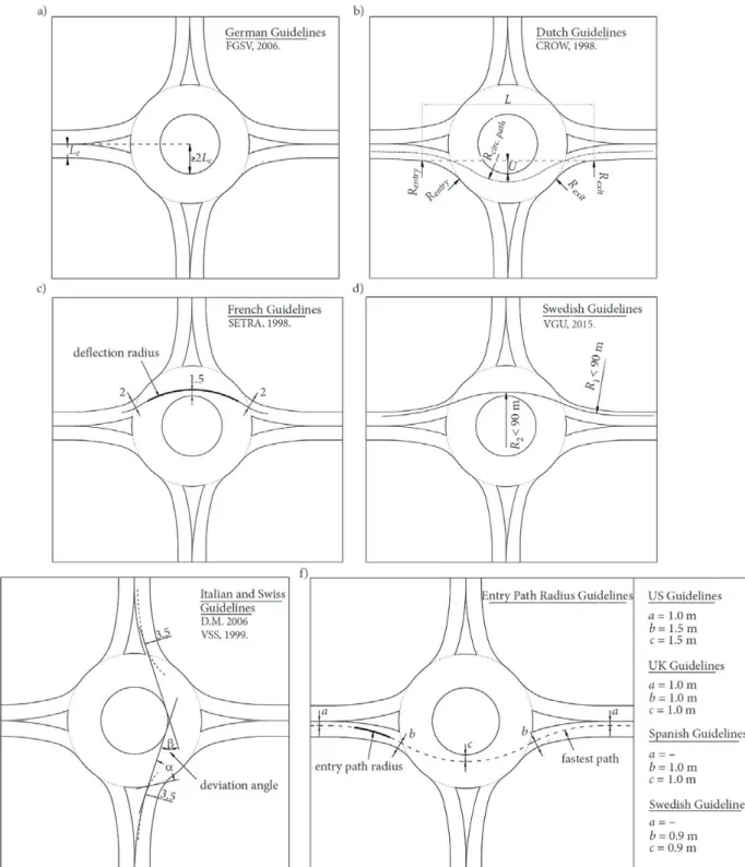
Almost all International roundabout design guidelines include specific requirements on how to control speeds, while approaching and negotiating the roundabout, con-sidering the vehicle path deflection. In detail, the main parameters used to control speeds at roundabouts by en-suring the vehicle path deflection are the deflection radius, the entry path radius and the deviation angle, defined be-low and better explained in Figure 1:
– The deflection radius is the radius of the vehicle path through the circulating roadway. The largest value of the radius is set to control the operational speeds on the roundabout. This method was formally proposed in UK and Australian Guidelines (Arndt, 2008), and later replaced by other methods, but is used in France. – The entry path radius is the path radius of a vehicle,
which is approaching the roundabout by entering the circulating roadway. It defined as the “minimum ra-dius on the fastest through path before the yield line” (NCHRP, 2010). It is possible to limit the speed of drivers who are entering in the roundabout, by limit-ing the entry path radius (Colonna, Berloco, Intini, Perruccio, & Ranieri, 2016). This approach is used in several countries (Afezolli & Paçi, 2012).
– The deviation angle is the angle included between the two tangent lines to the 3.5 m offsets of the entry and exit kerb radii as in Figure 1. Setting a minimum
value for this angle may lead to controlling the speeds of drivers who have to negotiate the roundabout, by ensuring an appropriate curved path. This approach is used in Italy and Switzerland.
Some other roundabout design standards use different geometric parameters to control the deflection of trajecto-ries from the ones listed above. For example, according to German standards, a satisfactory deflection is considered to be achieved when the radius of the central island is at least twice the entry lane width (Figure 1a).
The following Table 1 summarizes the parameters con-trolling the deflection of trajectories provided in different roundabout design standards reviewed (from the United States of America (USA), Australia, and some European countries), better explained in Figure 1.
While the aims of the above listed methods are simi-lar, the specific design requirements for achieving them are different. Clearly, independently of the specific need, deflection prescriptions limit the geometric roundabout configurations, usually chosen by the designers. For this reason, technical studies may help practitioners in ad-dressing the geometric design aspects of roundabouts with particular regard to the deflection requirements, which in some cases are hard to fulfil. Moreover, the main three deflection requirements are normally affected by the oth-er geometric elements of the roundabout, and the design process is usually iterative. Hence, providing practitioners with methods to know in advance the relationships be-tween different geometric roundabout parameters and the deflection requirements could be very helpful.
However, the literature specifically related to the topic of roundabout deflection is scarce. There are some
stud-Table 1. Deflection parameters for rural one-lane roundabouts in several countries
Deflection parameters
Country and Standard/Regulation
France Netherlands SwedenThe Spain UK USA Australia Switzerland Italy Germany
SE TR A (1998) CR O W (1998) Tra fik ver ket (2015) M ini ster io de Fo m en to (1999) UK H ig hwa ys A gen cy (2007) N CHRP (2010) Aum ann (A us tro ad s) (2015)
VSS (1999) Mini
ster o de lle Inf ra str ut tur
e e dei
Tra sp or ti (2006) FGSV (2006) Radius of
deflection ≤100 m ≤23 m ≤≤90 m or 30 m* Entry path
radius ≤≤90 m or 30 m* ≤100 m ≤100 m ≤≤52 m or 66 m** ≤desirable55*** m Deviation
angle ≥45
o in
case of
α < 70o ≥45 o
Lateral
displacement ≥ 2Lc
ies on the design aspects of roundabouts, which consider the entry path radius method in detail (see e.g. ARNDT, 2008; Easa & Mehmood, 2004; Flannery, 2001; Mehmood & Easa, 2006). The study by Easa and Mehmood (2004) specifically provides an optimized method for designing the geometry of roundabouts, also considering the deflec-tion requirements. However, the deviadeflec-tion angle method was mainly addressed by earlier studies from a safety per-spective (Sacchi, Bassani & Persaud, 2011; Sadeq & Sayed, 2016; Spacek, 2004). In a recent Italian study on rounda-bout crashes (Montella, 2011), a very large entry path ra-dius (R > 100 m) was identified as a contributory factor in almost 30% of the crashes.
Ambros, Novák, Borsos, Hóz, Kieć, Machciník, and Ondrejka (2016) developed accident prediction models for roundabouts, based on accident, traffic and geometric data for 72 roundabouts in four Central-European countries. They found injury accident frequencies increasing with the traffic volume and apron width, and decreasing with the deflection parameters (in terms of both entry and deviation angles).
This study is intended as a research contribution to deepen the comparison between the deflection methods for roundabout design, and it is specifically focused on the de-viation angle method. Designing a roundabout is an iterative process. In most cases, checking the roundabout deflection is the last step in the design process. Thereafter, the consist-ency between the speeds related to the entry, circulatory and exit (rarely) trajectories are verified. In several cases, the de-flection check gives a negative output and the designer has to repeat the design process, by modifying some geometric input parameters. This is the case of converting existing inter-sections into roundabouts, given some constraining bound-ary conditions (e.g. limited diameter or roads at intersections with angles different than 90°).
Starting from this evidence, the aims of the study are: – to review some key international practices for
ensur-ing path deflections at roundabouts;
– to find the minimum geometric standards for a ge-neric roundabout, which are able to satisfy the de-viation angle check (taking into consideration the Italian legislation);
– to compare results obtained from the simulation performed considering the deviation angle method (using the Italian reference standard) with the entry path radius method (using the US reference stand-ard) and the German method;
– to provide some possible improvements in standards using the deviation angle method (in particular the Italian one, used as a reference).
To reach this aim, the deflection angles of more than 7.000 hypothetical roundabouts plotted in a CAD envi-ronment were measured. A number of the considered roundabouts were checked with both the entry path radius and the German methods. The high number of roundabouts examined derives from the high number of geometrical parameters considered in the graphic simula-tion. A simulation of the variability of these parameters
was conducted, systematically, within the validity intervals indicated in the Italian roundabout geometric standard taken as a reference (Ministero delle Infrastrutture e dei Trasporti, 2006).
The remainder of the paper is structured as follows. Section 1 is devoted to present some International stand-ards on the deflection requirements. An overview of the Italian standard used as a reference for the design of roundabouts is presented in Section 2, while the methods employed for the research are detailed in Section 3. The following Section 4 presents the results obtained through the simulation of the geometry of the reconstructed roundabouts as well as the comparison between the de-viation angle and the method of the entry path radius. The results are discussed in Section 5, in which some pro-posals are also advanced for improving the Italian Stand-ard based on the results obtained. Conclusions about this study are then drawn, also giving some indications about possible future developments.
1. International comparison of roundabout deflection methods
In this section, the requirements provided by the main international standards to control the speed through the deflection are summarized. A generic depiction of the de-flection measures adopted in seven European countries, the USA and Australia, is given in Figure 1. Most other countries adopt one of the methods described or a com-bination thereof.
1.1. The deflection radius method The French method
According to The Design of Interurban Intersections on Major Roads. At-Grade Intersections (SETRA, 1998), the path deflection is the radius of the arc passing 1.5 m from the edge of the central island and 2 m from the edges of the entry and exit lanes (Figure 1c). Its radius should be less than 100 m. The recommended value is 30 m.
1.2. The entry path radius method The Spanish method
The Recomendaciones sobre glorietas (Ministerio de Fo-mento, 1999) set the maximum entry path radius to 100 m in order to ensure a reasonable entry speed (Figure 1f). However, this value corresponds to an entry speed equal about to 50 km/h. For this reason, the Spanish standard is closer to the Anglo-Saxon standards than other standards from continental Europe.
The UK method
as-sumed the smallest radius of this path. It is measured over the smallest best-fit circular curve over a distance of 25 m on the entry path close to the give way line, but less than or equal to 50 m from it. The entry path radius must be lower than or equal to 70 m at urban compact rounda-bouts and 100 m at all other roundarounda-bouts.
The US method
Guidelines about roundabout design in the US are provid-ed in Roundabouts: An Informational Guide – second Edi-tion (NCHRP, 2010), replacing the first ediEdi-tion (NCHRP, 2000). Those guidelines use a method for plotting the en-try path similar to the British method. They also recom-mend a maximum theoretical entry design speed.
In detail, the entry path radius is the smallest best-fit circular curve of at least 20 m to 25 m measured on the fastest path, advanced less than or equal to 50 m from the entrance line. The fastest path is obtained in turn by drawing the curve constrained by the offsets indicated in Figure 1f. Hence, in correspondence to the entry radius so determined, the speeds must be lower than the speeds reported in Table 2. The safety check is aimed at the op-timum goal of obtaining the smallest possible speed dif-ferential between the traffic flowing in the circulatory lane of the roundabout and the traffic entering from the entry lanes.
Eqs 1–2 provide the simplified relationship between speed and radius reported in (NCHRP, 2010), used to as-sign the speed to a given entry path radius, in case of posi-tive or negaposi-tive super elevation.
0.3861 3.4415
V= R for e = +0.02, (1)
0.3673
3.4614
V= R for e = –0.02, (2)
where V – speeds (mph); R – radius (ft); e – super eleva-tion (ft/ft).
1.3. The deviation angle method The Swiss method
The SN 640 263 Carrefours giratoires (VSS, 1999) recom-mends observing a deviation angle β ≥ 45° (Figure 1e). In general, the need for a deviation angle β ≥ 45° is satisfied in the case of roundabouts with four legs having a large in-scribed circle diameter (ICD) (>32 m). The Swiss standard also provides the correlation between the deflection angle β and the entry angle α (between the vehicle entry path and
the tangent to the inscribed circle diameter): the recom-mendation of β ≥ 45° is mandatory in the case of α < 70°.
However, the same standard also accepts smaller β an-gles to calculate the circulatory speeds used for visibility checks (40 km/h for β < 20°, 35 km/h for 20° ≤ β ≤ 45°, 30 km/h for β > 45°). In fact, the Swiss standard is composed of recommendations and therefore allows more freedom to the designers.
The Italian method
The Italian deflection requirement in DM 2006 – Guide-lines for the Design of Road Intersections (Ministry of Pub-lic Works and Transport, 2006) is based on the deviation angle β, the same as the Swiss one. The deviation angle is obtained through the following process:
a) draw the offset curve at 3.50 m of both the entry and exit kerb radii;
b) plot the lines at a tangent to both the offset curves drawn at the earlier stage, and the non-mountable kerbs of the central island;
c) measure the angle included between the two ob-tained tangent lines.
A deviation angle β value greater than or equal to 45° is recommended for each crossing leg. This requirement is valid for all types of roundabouts, independently of their diameters.
1.4. Other methods The Dutch method
Concerning the speed reduction to be obtained at rural one-lane roundabouts, the Dutch guidelines (CROW, 1998) differ from the FHWA (U.S. Federal Highway Ad-ministration) guidelines (approach speed of 35 km/h and 40 km/h, respectively). On single-lane roundabouts, all aspects of safety improve when the largest vehicle path curvature is used (Figure 1b). According to the Dutch regulations, the relationship between the speed V on the curved path and its radius R is represented by Eq. (3) and the speed through the roundabout is variable between 30 km/h and 35 km/h. Hence, the deflection radius falls in the range between 16 m and 23 m.
7.4
i i
V = R . (3)
The German method
The German guidelines (FGSV, 2006) require the lateral displacement of the vehicle entering the roundabout to be at least twice the approach lane width (Lc): Rint≥ 2Lc, as shown in Figure 1a.
The Swedish method
The Swedish guidelines (Trafikverket, 2015) require both the entry path radius and the deflection radius to be small-er than a given threshold (Figure 1d). This value is equal to 90 m for design speed ≤60 km/h (rural roundabouts), and 30 m for design speed ≤30 km/h (urban roundabouts). Table 2. Recommended maximum entry design speeds
(Rodegerdts et al., 2010)
Site category Recommended maximum theoretical entry design speed
Mini-Roundabout 20 mph (30 km/h)
Single lane 25 mph (40 km/h)
2. Overview of the Italian roundabout design standards
Since the Italian standard has been used as a reference in the simulations carried out, it is briefly introduced as follows. Among the geometric standards considered as a reference for conducting the analysis, the Italian standards were preferred to the Swiss ones, because they need further developments.
The Italian DM 2006 “Functional and geometric Stand-ard for building road intersections” also includes
“Round-about Intersections”, very concise specific information about the circular intersections. The Italian nomenclature is different from any of the foreign ones considered in this study as regards roundabout dimensions, except for mini roundabouts with some slight differences (Tollazzi, 2015).
The Standard considers three basic categories of roundabouts, according to the ICD, valid both in rural and in urban contexts:
– large (conventional) roundabouts (with 40 ≤ ICD ≤
50 m);
– compact roundabouts (with 25 ≤ ICD < 40 m);
– mini roundabouts (with 14 ≤ ICD < 25).
In this article, the word “conventional roundabout” translated from the Italian standard was converted into “large roundabouts” to prevent misunderstandings about the International meaning of “conventional roundabouts”. A further distinguishing element, among the types of round-abouts, is the central island design, which may be partly mountable (truck apron) in the case of mini roundabouts with ICD included between 25 and 18 m, while it becomes fully mountable for those with ICD included between 18 and 14 m. The compact and large roundabouts are
charac-terized by non-mountable kerbs. Furthermore, the circula-tory roadway must always be organized on a single lane.
The widths of the modular elements stated in the Stan-dard are reported in Table 3.
3. Research method
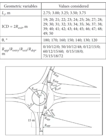
For the aims of the research stated in the Introduction, more than 7.000 roundabouts were drawn in a CAD en-vironment, and the deviation angle was reconstructed for each of them. The roundabouts drawn are not existing roundabouts, but rather hypothetically plausible ones, according to the Italian standards. The study considers only one-lane roundabout in rural areas, with divisional islands, and without pedestrian or bicycle crossings, side-walks or traffic lights.
The high number of roundabouts drawn is due to the geometric parameters used as variables (Figure 2), which were selected by varying according to the ranges provided in the Italian standard (Table 3). A deviation angle ≥45°
in-dicates a good deflection of trajectories at roundabouts, for both the Italian and Swiss standards. For each combination of the geometric parameters, the smallest ICD value was obtained, for which the deviation angle check is satisfied.
The approach lane width (Lc) is assumed equal to the departure lane width, taking into account all the possible widths laid down by the Italian standard. Roundabouts with an ICD of less than 19.00 m were excluded from the analysis because they are characterized by a fully mount-able central island. In these cases, the lack of a non-mountable kerb around the central island makes the con-struction of the deviation angle impossible as indicated by the standard. Roundabouts with opposite legs inclined, up to 120 degrees, have been considered to take into account the cases where roads at intersections conflict with angles different than 90°.
Since the Italian standard potentially allows any dimen-sion for the entry (Rentry), approaching (Rapp), exit (Rexit) and departing radii (Rdep), the choice of Rentryand Rexit
was made by taking into account the good design prac-tices and guidance of central European countries presented before (Kennedy, 2007; Montella, Turner, Chiaradonna & Aldridge, 2013). Regarding the approaching and departing radii, the Swiss standard (VSS, 1999), providing the Rapp to be 5 times the Rentry, and the Rdep to be 4 times the Rexit, is used as reference. The case of the absence of the approach-ing and departapproach-ing radius has also been considered to repre-sent many real cases of roundabouts in Europe. The ranges of variation of the parameters, and the combinations of
Rapp, Rentry, Rexit and Rdep used are shown in Table. 4.
The analysis of the considered hypothetical round-abouts was aimed at identifying the relationships between the deviation angle and the geometric parameters of roundabouts. Thereafter, a comparison between the devia-tion angle method and other two Internadevia-tional methods is carried out, by using the same roundabouts plotted in CAD environment by using the Italian Standards (to allow a consistent comparison).
Table 3. Widths of modular elements – Italian standard
Modular element Inscribed circle diameter, m Widths, m
Lanes of the circulatory roadway* for one lane entry legs
≥40 6.00
from 25 to 40 7.00
from 14 to 25 7.00–8.00
Lanes of the circulatory roadway* for two lane entry legs
≥40 9.00
<40 8.50–9.00
Entry legs** 3,50 (one lane)6.00 (two lane)
Exit legs* <25 4.00
≥25 4.50
Notes: *it must always be organized on a single lane, **organized at most with two lanes.
Table 4. Values of the geometric variables considered
Geometric variables Values considered
Lc,m 2.75; 3.00; 3.25; 3.50; 3.75
ICD = 2Rexit,m
19; 20; 21; 22; 23; 24; 25; 26; 27; 28; 29; 30; 31; 32; 33; 34; 35; 36; 37; 38; 39; 40; 41; 42; 43; 44; 45; 46; 47; 48; 49; 50
θ, ° 180; 170; 160; 150; 140; 130; 120
Rapp/Rentry/Rexit/Rdep, m
0/10/12/0; 50/10/12/48; 0/12/15/0; 60/12/15/60; 0/15/18/0;
75/15/18/72
The two methods on which the comparison is based are the entry path radius method and the German method. The first method was selected since it is the most widespread in the sample of countries considered in this article. In par-ticular, the US graphical method was selected, rather than the British, Spanish or Swedish ones, since the “a”, “b”, and “c” coefficients shown in Figure 1f were deemed as more realistic for the trajectories of several types of vehicles. The second method selected for the comparison is the German method, which seems to be different from all the other ones.
As regards the entry path radius method, the fastest paths of the roundabouts previously tested were recon-structed by considering the indications of the US guidelines (Figure 1f and Sub-Section 1.2), and by varying the same geometric parameters as in the analysis before conducted (ICD, θ, Lc and Rapp/Rentry/Rexit/Rdep). For each hypothetical roundabout, the fastest path was drawn and the related entry path radius was obtained. Hence, the entry speed was com-puted, by using Eq. (1) (related to positive super elevation). As regards the German method, the check provides a positive outcome when the radius of the circulatory island is at least twice the approach lane width. Hence, to get the smallest ICD values, in order to satisfy the rule, the fol-lowing equation was employed:
4Lc + 2(Lcir + 0.5), (4)
where 0.5 is the width of the left shoulder (for all types of roundabouts) (m); and the value of Lcir is shown in Table 3 (in this case, it is always set to 7.00 m) (m).
4. Results
The main results of the analysis are discussed in this section. The relationships between different geometric parameters of roundabouts and the deviation angle are reported first. Subsequently, the comparison between the deviation angle method, the entry path radius method (USA) and the German method is discussed.
4.1. Identifying the relationships between
geometric design parameters of roundabouts and the deviation angle
The general results of the analysis are listed below: 1) the increase in ICD positively influences the
devia-tion angle check (i.e. the angle increases);
2) reducing θ negatively influences the deviation angle check (i.e. the angle decreases);
3) reducing Lcpositively influences the deviation angle check;
4) the presence and the increase of the approaching (Rapp) and the departing radius (Rdep) negatively influence the deviation angle requirement;
5) differences in the circulatory roadway width (Lcir) between compact and large roundabouts and be-tween compact and mini roundabouts (Table 3) negatively influence the deviation angle check;
6) the Italian β recommendation (β no less than 45°) fails for any of the mini roundabouts or for many compact roundabouts (also for θ equal to 180°); 7) the Italian β recommendation (β no less than 45°)
fails for θ below 140°.
The considerations listed above from point 1 to point 4 may be considered as universally valid, independently of the geographical area, whereas the results highlighted in points 5 to 7 are instead related to specific Italian geo-metric standards.
The first two findings about ICD and θ are predictable from immediate geometric considerations. As regards the approach and the departure lane width (Lc), they depend on the roads approaching the roundabout. Therefore, it is difficult to act easily on these parameters to improve the deflection.
As concerns the approaching and the departing radius, in rural roundabouts, usually devoid of pedestrian or bi-cycle crossings, introducing both Rapp and Rdep improve the intersection efficiency because it:
1) increases the roundabout capacity, 2) reduces the average occupation time,
3) ensures a proper separation among opposite traf-fic flows through the installation of larger splitter islands.
Guidance from reference standards (even Internation-al) indicating where the approaching radius has to begin is lacking and then, its beginning was set at 15 m from the circulatory roadway in this study. In this way, it is pos-sible to optimize the connection between Rapp and Rentry (or Rdep and Rexit), by allowing the insertion of sufficiently large splitter islands.
As regards the circulatory roadway (Lcir), the results show that its width greatly affects the deviation angle: the larger the width, the smaller the angle. As shown in Ta-ble 3, the Italian standard provides the increase in Lcir in correspondence with the decrease in ICD. A possible so-lution consists in assuming the Lcirconstant (as provided in the Swiss standard) and made varying the truck apron. This solution is discussed later in this paper and general-ized for other contexts.
As regards the θ angle, on one hand the deviation angle check is unmet for θ less than 140°, although it is accomplished for θ values close to 180°, by modifying the other geometric parameters. Hence, the deviation angle check can also be satisfied for legs crossing at roundabouts with θ less than 90°.
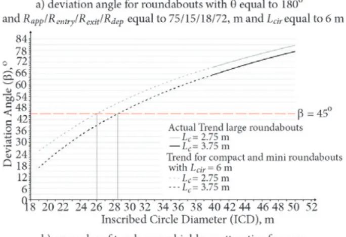
In addition to the qualitative discussion about these geometric relationships, the resulting deviation angles for different combinations of the geometric parameters: ICD,
θ, Lc, Rapp, Rentry, Rexit, Rdep have been computed. A
Figure 3 (reported as an example of all the 42 diagrams plotted) shows the deviation angles for roundabouts with θ equal to 180° and Rapp/Rentry/Rexit/Rdep equal to 75/15/18/72, with ICD and Lcvarying. In this case, the β recommendation is valid for roundabouts with an ICD more than 30.0 m or 32.5 m (compact roundabouts) de-pending on Lc.
It is important to note that roundabouts having ICD values equal to 25 m belong to either the mini or compact categories (which are drawn by using different values of
Lcir). Hence, 10 β values are shown, instead of 5. The same remark is valid for ICD equal to 40 m, that is the bound-ary between large and compact roundabouts.
4.2. Comparing the deviation angle method
(Italy) with the entry path radius method (USA) and the German method
The comparison between the deviation angle method and other two International methods is discussed in this section. As regards the entry path radius method, the outcome of the checks is governed by the speed value (V) of the en-try path radius R1, summarized in the following diagrams, where the range of validity of Table 2 is also shown.
Figure 4 reports the speeds correspondent with the en-try path radius as a function of ICD; for different values of
Lc and for Rapp/Rentry/Rexit/Rdep equal to 60/12/15/60 and
Rapp/Rentry/Rexit/Rdep equal to 75/15/18/72.
To note, the value of entry path radius (and the corre-sponding speed) appears to be independent of the θ angle. In fact, the deflection check in the US Guidelines is solely based on the entry radius measured on the fastest path, constrained by a fixed offset on the entrance line (Fig-ure 1f). Hence, the rest of the fastest path is constrained by the θ angle, whereas the entry path radius cannot be influenced by it. However, the deviation angle method is strongly dependent on the θ angle, as discussed in sec-tion 3 (Table 4).
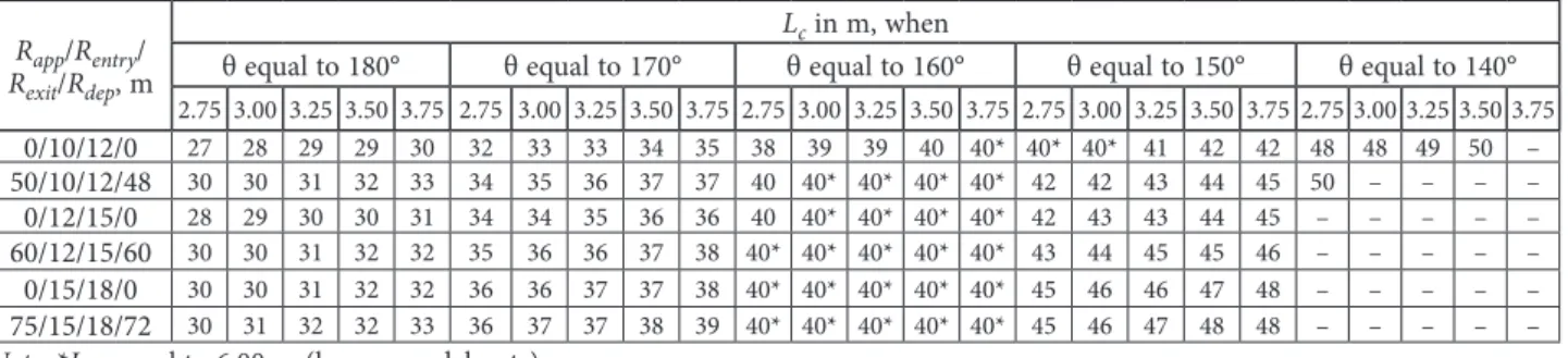
Table 5 reports the smallest ICD values to be used for fulfilling the entry path radius method (US standard), the German Method and the deviation angle method (Italian standard) respectively, by varying Lc and θ, for
Rapp/Rentry/Rexit/Rdep equal to 60/12/15/60 and
Rapp/Rentry/Rexit/Rdep equal to 75/15/18/72. Those results
are derived from Figure 4, Table 4 and Eq. (4).
Table 5. Minimum ICD values, which satisfy the β recommendation (β up to 45°), according to different geometric parameters of the roundabouts
Rapp/Rentry/ Rexit/Rdep, m
Lc in m, when
θ equal to 180° θ equal to 170° θequal to 160° θequal to 150° θ equal to 140°
2.75 3.00 3.25 3.50 3.75 2.75 3.00 3.25 3.50 3.75 2.75 3.00 3.25 3.50 3.75 2.75 3.00 3.25 3.50 3.75 2.75 3.00 3.25 3.50 3.75
0/10/12/0 27 28 29 29 30 32 33 33 34 35 38 39 39 40 40* 40* 40* 41 42 42 48 48 49 50 –
50/10/12/48 30 30 31 32 33 34 35 36 37 37 40 40* 40* 40* 40* 42 42 43 44 45 50 – – – –
0/12/15/0 28 29 30 30 31 34 34 35 36 36 40 40* 40* 40* 40* 42 43 43 44 45 – – – – –
60/12/15/60 30 30 31 32 32 35 36 36 37 38 40* 40* 40* 40* 40* 43 44 45 45 46 – – – – –
0/15/18/0 30 30 31 32 32 36 36 37 37 38 40* 40* 40* 40* 40* 45 46 46 47 48 – – – – –
75/15/18/72 30 31 32 32 33 36 37 37 38 39 40* 40* 40* 40* 40* 45 46 47 48 48 – – – – –
Note: *Lcir equal to 6.00 m (large roundabouts).
Figure 3. Deviation angle for roundabouts with θ equal to 180° and Rapp/Rentry/Rexit/Rdepequal to 75/15/18/72, m
As for the entry path radius method, the German method is also independent of the θ angle. Furthermore, both meth-ods are independent of the radius Rapp,Rentry, Rexit and Rdep. Hence, this is deemed by the authors as a weakness of US standards (and the other standards based on the entry path radius) as well as in the German method, both independent of the angle θ and the radius of the entry and the exit legs. This finding becomes crucial in the case of conversion of existing junctions into roundabouts, when roads intersect with angles smaller than 90° and the geometry of the roads cannot be varied due to boundary restrictions.
Furthermore, the minimum ICD value to satisfy the US standard is fixed, whereas the same check conducted through the German method varies according to the Lc value. Comparing the results of the Italian method (even considering only θ equal to 180°) with the other methods, the Italian method proves to be the most conservative. In fact, in the same boundary conditions, higher diameters are necessary to satisfy the Italian deviation angle check. Moreover, it takes into account numerous geometric char-acteristics, ignored in the other two methods.
5. Discussion
The results presented in the previous section are discussed below. Starting from the results on the relationships be-tween geometric parameters of the roundabouts and the deviation angle, the focus of the discussion is on both the comparison between the methods employed and the pro-posal of improvements for the Italian standard. Regarding the comparison between the three methods, they lead to similar results for roundabouts characterized by θ equal to 180°. However, reducing θ to 170° highlights that both the entry path radius method and the German method are much less restrictive than the deviation angle method. In fact, the first two methods are unrelated to the θ angle. This is a general issue, especially for converting four-leg intersections without traffic lights into roundabouts when the roads intersect with angles smaller than 90°.
To note, by using the results of the analysis carried out, practitioners know in advance whether the requirement (or recommendation) about the deviation angle is satisfied, once the main design parameters are known. However, al-though the analysis has been conducted according to the construction provided by the Italian Standard, the results serve as a term of comparison independently of the specific local standards, in the case of similar roundabouts.
The analysis of the same results leads to remarks about the weaknesses of the Italian standard. Several round-abouts possibly realizable in Italy unmeet the β recom-mendation. The recommendation is practically almost never satisfied for θ less than 140°. However, also for roundabouts with θ equal to 180°, the recommendation is always unmet for mini roundabouts and often unmet for compact roundabouts. On the contrary, the recom-mendation is always satisfied for large roundabouts and for 150° ≤ θ ≤ 180°. Values of Lcir varying between large and compact roundabouts lead to non-compliance with the β recommendation for several compact roundabouts. Whereas, although Lcir is kept equal to 6.00 m for compact roundabouts, the minimum ICD value reported in Table 5 shows a higher variability even for θ equal to 160° (instead of being almost always equal to 40 m).
Another interesting result to highlight is that, as well as the Italian standard, even the US and German verification give a negative deflection check for all mini roundabouts. In fact, the minimum ICD required to satisfy the deflec-tion requirement based on the entry path radius method is 30 m, whereas it is between 26 m and 30 m according to the German method.
Hence, research that is more specific is needed on the design of mini roundabouts with respect to deflection, in-dependently of the method used and the particular coun-try standards.
Moreover, since different remarks about the deflection requirement arose for different types of roundabouts, some proposals for improvements are provided below, differentiat-ed for roundabout type, considering the rural context. Since Table 5.Minimum value of ICD able to satisfy the entry path radius and deflection angle methods
Radius Lc, m
ICDmin, m
USA ICDGermany min, m ICDItalymin, m
all values of θ all values of θ θ equal to 180° θ equal to 170° θ equal to 160° θ equal to 150° θ equal to 140°
Rapp/Rentry/Rexit/Rdep equal to
60/12/15/60, m
2.75 30 26 30 35 40 43 –
3.00 30 27 30 36 40 44 –
3.25 30 28 31 36 40 45 –
3.50 30 29 32 37 40 45 –
3.75 30 30 32 38 40 46 –
Rapp/Rentry/Rexit/Rdep equal to
75/15/18/72, m
2.75 30 26 30 36 40 45 –
3.00 30 27 31 37 40 46 –
3.25 30 28 32 37 40 47 –
3.50 30 29 32 38 40 48 –
this study used the geometric Italian standard as a reference, the following recommendations are essentially related to the Italian types of roundabouts (large, compact, mini). Poten-tially, they could be applied to other countries with similar geometric elements. However, further studies are needed to better address transferring these results to other countries.
5.1. Large roundabouts (ICD ≥ 40 m)
The β recommendation was fulfilled for all conventional roundabouts with θ angle included between 160° and 180°. The β recommendation is also satisfied for θ equal to 150°, especially for roundabouts characterized by small entry and exit radii or by both approaching and departing radii absent. Hence, further improvements are disregarded.
5.2. Compact roundabouts (25 m ≤ ICD < 40 m)
The β recommendation was only fulfilled for some com-pact roundabouts. When either the angle θ is reduced, the approaching and the departing radii are inserted, or the en-try and the exit radii are increased, the situation gets worse. The differences in the circulatory roadway widths in the Italian standard, between compact and mini round-abouts (7 m and 8 m, respectively) and between compact and conventional roundabouts (7 m and 6 m, respectively) negatively affect the β check. Assuming a constant width of the circulatory roadway equal to 6 m may be an im-provement, even for compact and mini roundabouts, in
order to cut the discontinuities at ICD equal to 40 m and 25 m. The same diagram as in Figure 3 has been plotted in Figure 5a, considering a single width (with θ equal to 180° and the unfavourable case of Rapp/Rentry/Rexit/Rdepequal to 75/15/18/72, m).
The proposed solution about the unique circulatory roadway width is eventually completed by inserting a truck apron in compact roundabouts too, to allow easy manoeuvring of heavy vehicles. The Italian standard rec-ommends drawing the β angle by plotting the tangent lines to the non-mountable kerb of the central island. In fact, the truck apron is realized with a fully mountable kerb and with comfortably carriage able materials. A proposal for an improved solution consists in realizing the truck apron with a material easily mountable by heavy vehicles, but at the same time highly unattractive for cars. Several materials and solutions are potentially usable for giving discomfort to the car drivers in terms of noise and roll-ing due to surface irregularities. Some examples are pro-posed in Figure 5b. Similar solutions are already provided in Dutch and in UK guidelines. The width of the truck apron will depend on the dimensions of the heavy vehicles (resulting in the swept path), related to the inscribed circle diameter. Opting for a flat surface will be possible (to cut noise), with the same super elevation of the circulatory roadway (to cut the chance of overturning), but with a mountable kerb of 5 cm to 7 cm high.
Using truck aprons highly unattractive for cars, the deviation angle is proposed to be drawn by plotting the tangent to the outer part of the truck apron instead of the innermost, ensuring the β checks for almost all compact roundabouts. The case shown (check satisfied for ICD equal to 26.25 m with Lc equal to 2.75 m and for ICD equal to 28.5 m with Lc equal to 3.75 m) is the worst case for the used radii dimensions. The recommendation is sat-isfied with ICD equal to 25 m, being both the lower entry and exit radii present.
Moreover, a slightly lower limit of the angle β is pro-posed, in order to allow greater design versatility for com-pact roundabouts, by reducing it from 45 to 40 degrees, as required by some local Swiss Guidelines. In fact, some studies have shown accident increasing for deviation an-gles less than 40 (Huber & Bühlmann, 1994).
5.3. Mini roundabouts (14 ≤ ICD < 25 m)
Mini roundabouts need specific regulations to cut the ap-proaching and circulating speeds. For mini roundabouts, the β angle is potentially usable as an indicator of traffic calming measures to be implemented. In particular, for deviation angles between 30 and 40 degrees, the imple-mentation of light traffic calming devices (enhanced horizontal and vertical road signs, rumble strips, optical devices) are proposed. For β angles less than 30°, (consid-ered possible by Huber & Bühlmann, 1994), implementing more significant traffic calming devices is adviced (raised platforms, chicanes, automatic speed checks).
Several International studies, Guidelines and Stan-dards include implement traffic calming devices in mini roundabouts (Antov, Abel, Sürje, Rõuk, & Rõivas, 2009; Rossi, Gastaldi, Biondi, & Mulatti, 2013; WSDOT, 2017). However, further studies have to be carried out to relate each traffic-calming device to the context and to the main function of the roundabout under examination. Finally, to make this proposal applicable, traffic-calming devices have to be standardized in countries where standards and regulations about their design are lacking.
Moreover, the assessment of geometric elements of mini roundabouts (and particularly the truck apron) has to be based on the worst design vehicles (in terms of di-mensions) supposed in the roundabout traffic flow. This recommendation is proposed as an improvement for stan-dards of countries where it is absent, such as in Italy.
Conclusions
This study was focused on the deviation angle method (used by Italian and Swiss standards), but a comparison with the entry path radius method (used in several coun-tries) and with the German method has been carried out to check their compatibility or differences. The study was limited to single-lane four-legged roundabouts in rural ar-eas. Moreover, the Italian standard was used to build more than 7.000 hypothetical roundabouts in a Computer-Aid-ed Design environment, to check their deviation angle and compare the results with both the US entry path radius method and with the German method.
The following general conclusions from this study are drawn:
1. This study helps practitioners to know in advance the deflection angle value before the design process, once the boundary conditions are known.
2. The entry path radius and the German methods are much less restrictive than the deviation angle method for roundabouts with non-orthogonal intersecting roads or with different entry and exit legs radii, since the deviation angle is strongly dependent on the mu-tual inclination of the roads and on these radii. 3. The three methods considered led to a negative
check for all mini roundabouts (inscribed circle di-ameter is equal from 14–25 m).
The study has also led to the following conclusions specifically devoted to improve Italian regulations:
1. The use of a constant width of the circulatory road-way assumed to be equal to 6 m in this study, with a truck apron highly unattractive for cars, extend the Italian deviation angle recommendation (β more than 45°) to be valid for almost all roundabouts with an inscribed circle diameter greater than 25 m. 2. Mini roundabouts need specific regulation in
stan-dards of countries (e.g. Italy) where they are consid-ered in a similar fashion and with similar arrange-ments for larger roundabouts.
To some extent, some of the findings are transferrable to other countries, whereas some others are specifically
related to the standards used, as explained in the paper. Hence, further investigations are needed for roundabouts in urban areas and for multi-lane roundabouts in rural areas. Nevertheless, a more general framework is a chal-lenge for future studies, in order to spread the results of comparison between different deflection methods in other countries, through general tools.
References
Afezolli, A., & Paçi., E. (2012). Roundabouts control, using the maximum entry path radii speed. Journal of Institute Alb-Shkenca, 2, 277–283. ISSN 2073-2244.
Ambros, J., Novák, J., Borsos, A., Hóz, E., Kieć, M., Machciník, Š., & Ondrejka, R. (2016). Central European comparative study of traffic safety on roundabouts. Transportation Research Proce-dia, 14, 4200–4208. https://doi.org/10.1016/j.trpro.2016.05.391
Antov, D., Abel, K., Sürje, P., Rouk, H., & Roivas, T. (2009). Speed reduction effects of urban roundabouts. Baltic Journal of Road & Bridge Engineering, 4(1), 22–26.
https://doi.org/10.3846/1822-427X.2009.4.22-26
Arndt, O. (2008). Speed control at roundabouts: use of maxi-mum entry path radii. ARRB Conference, 23rd. Adelaide, South Australia, Australia.
Aumann, P. (2015). Guide to road design part 4B: roundabouts (No. AGRD04B-15). Austroads. Australia.
Bezina, Š., Stančerić, I., & Ahac, S. (2017). Design vehicles and roundabout safety – review of Croatian design guidelines. Transport Infrastructure and Systems: Proceedings of the AIIT International Congress on Transport Infrastructure and Sys-tems (p. 237). Rome, Italy. CRC Press.
https://doi.org/10.1201/9781315281896-33
Colonna, P., Berloco, N., Intini, P., Perruccio, A., & Ranieri, V. (2016). Evaluating skidding risk of a road layout for all types of vehicles. Transportation Research Record: Journal of the Transportation Research Board, (2591), 94–102.
https://doi.org/10.3141/2591-11
CROW (1998). Eenheid in Rotondes [Standards for Round-abouts], publicatie 126.
Easa, S., & Mehmood, A. (2004). Optimizing geometric design of single-lane roundabouts: consistency analysis. Canadian Journal of Civil Engineering, 31(6), 1024–1038.
https://doi.org/10.1139/l04-066
Forschungsgesellschaft fur Strassen und Verkherswesen [Re-search Institute for Road and Transport] (FGSV). (2006). Merkblatt fur die Anlage von Kreisverkehren [Guide for the Installation of Roundabouts].
Flannery, A. (2001). Geometric design and safety aspects of roundabouts. Transportation Research Record: Journal of the Transportation Research Board, (1751), 76–81.
https://doi.org/10.3141/1751-09
Huber, C., & Bühlmann, F. (1994). Sicherheit von Kreiselanlagen, Erfahrungen und vorl vorle Empfehlungen [Safety at round-abouts, experiences and preliminary recommendations]. Swiss Bureau for Accident Prevention (BFU), Berne, Switzerland. Kennedy, J. (2007). International comparison of roundabout
de-sign guidelines. TRL.
Mehmood, A., & Easa, S. M. (2006). Optimizing geometric design of roundabouts: multi-objective analysis. Canadian Journal of Civil Engineering, 33(1), 29–40. https://doi.org/10.1139/l05-078
Ministero delle Infrastrutture e dei Trasporti [Ministry of Public Works and Transport]. (2006). Decreto Ministeriale: Norme funzionali e geometriche per la costruzione delle intersezioni stradali [Operational and geometric standards for the con-struction of road intersections]. Gazzetta Ufficiale (170). Montella, A. (2011). Identifying crash contributory factors at
urban roundabouts and using association rules to explore their relationships to different crash types. Accident Analysis & Prevention, 43(4), 1451–1463.
https://doi.org/10.1016/j.aap.2011.02.023
Montella, A., Turner, S., Chiaradonna, S., & Aldridge, D. (2013). International overview of roundabout design practices and insights for improvement of the Italian standard. Canadian Journal of Civil Engineering, 40(12), 1215–1226.
https://doi.org/10.1139/cjce-2013-0123
National Cooperative Highway Research Program (NCHRP). (2000, 2010). Roundabouts: an Informational Guide. Wash-ington DC.
Pilko, H. (2017). Roundabout design guidelines: case study of Croatia. Transport Infrastructure and Systems: Proceedings of the AIIT International Congress on Transport Infrastructure and Systems (p. 9).Rome, Italy. CRC Press.
https://doi.org/10.1201/9781315281896-3
Rodegerdts, L., et al. (2010). Roundabouts: an informational guide (National Cooperative Highway Research Program, Report 672, Second Edition). Transportation Research Board. Rossi, R., Gastaldi, M., Biondi, F., & Mulatti, C. (2013). Warning sound to affect perceived speed in approaching roundabouts: experiments with a driving simulator. Procedia-Social and Be-havioral Sciences, 87, 269–278.
https://doi.org/10.1016/j.sbspro.2013.10.609
Sacchi, E., Bassani, M., & Persaud, B. (2011). Comparison of safety performance models for urban roundabouts in Italy and other countries. Transportation Research Record: Jour-nal of the Transportation Research Board, (2265), 253–259.
https://doi.org/10.3141/2265-28
Sadeq, H., & Sayed, T. (2016). Automated roundabout safety analysis: diagnosis and remedy of safety problems. Journal of Transportation Engineering, 142(12), 04016062.
https://doi.org/10.1061/(asce)te.1943-5436.0000887
Service d’études Techniques des Routes et Autoroutes [Service of technical studies on highways and freeways] (SETRA). (1998). The design of interurban intersections on major roads: at-grade intersections. Centre de la Sécurité et des Techniques Routières. Spacek, P. (2004). Basis of the Swiss design standard for round-abouts. Transportation Research Record: Journal of the Trans-portation Research Board, (1881), 27–35.
https://doi.org/10.3141/1881-04
Schweizerischer Verband der Strassen- und Verkehrsfachleute [Swiss Association of Road and Transportation Experts] (VSS). (1999). Carrefours, Carrefours Giratoires [Intersections. Roundabouts]. SN 640 263. Zurich, Switzerland.
Tollazzi, T. (2015). Alternative Types of Roundabouts. An Information-al Guide. Springer.https://doi.org/10.1007/978-3-319-09084-9
Trafikverket [Swedish Transport Administration]. (2015). Pub-likation 2015:087. VGU (Vägar och gators utformning) [Guide-lines for the design of roads and streets].
UK Highways Agency. (2007). Design manual for roads and bridges. TD 16/07: Geometric design of roundabouts.