Optimizing Architecture of DSRC Device By Using Component Reuse
1B.Mounica,2N.G.N.Prasad 1(P.G.STUDENT) M.Tech in VLSISD,2
Assistant Professorin VLSISD
Dept. Electronics and Communication Engineering Kakinada Institute of Engineering and Technology,
Korangi,AP,INDIA
Abstract—Devoted short-extend correspondence (DSRC) is a developing method to push the keen transportation framework into our day by day life. The DSRC norms for the most part receive FM0 and Manchester codes to achieve dc-adjust, upgrading the flag unwavering quality. By the by, the coding-differences between the FM0 and Manchester codes genuinely constrains the possibility to plan a completely reused VLSI engineering for both. In this paper, the likeness arranged rationale improvement (SOLS) strategy is proposed to conquer this confinement. The SOLS strategy enhances the equipment use rate from 57.14% to 100% for both FM0 and Manchester encodings. Differential Manchester can enhance clamor resistance over Manchester. Range change for FM0/Differential Manchester has been expanded to 47% from 16% of Manchester
Key words —Dedicated short-run correspondence (DSRC),FM0, Manchester, VLSI.
I. INTRODUCTION
THE devoted short-go correspondence (DSRC) is a convention for maybe a couple way medium range correspondence particularly for clever transportation frameworks. The DSRC can be quickly ordered into two classes: car to vehicle and car to-roadside. In vehicle to-car, the DSRC empowers the message sending and broadcasting among autos for wellbeing issues and open data declaration. The wellbeing issues incorporate blind side, crossing point cautioning, between auto separation, and impact alert. The car to-roadside concentrates on the shrewd transportation administration, for example, electronic toll gathering (ETC) framework. With ETC, the toll collecting is electrically proficient with the
administration, and gas-refueling. Hence, the DSRC framework assumes an essential part in cutting edge car industry.
asdc-discretionary paired arrangement, which is hard to get dc-adjust. The motivations behind FM0 and Manchester codes can give the transmitted flag dc-adjust. Both FM0 and Manchester codes are broadly received in encoding for down connection. The VLSI designs of FM0 and Manchester encoders are reviewedas takes after.
II. CODING PRINCIPLES OF FM0 CODE AND MANCHESTER CODE
In the accompanying examination, the clock flag and the info information are shortened as CLK, and X, separately. With the above parameters, the coding standards of FM0 and Manchester codes are talked about as takes after.
A. FM0 Encoding
As appeared in Fig. 2, for every X, the FM0 code comprises of two sections: one for previous half cycle of CLK, An, and the other one for some other time half cycle of CLK, B. Coding standard of FM0 is recorded as the accompanying three guidelines.
1) If X is the rationale 0, the FM0 code must display atransition amongst An and B.
2) If X is the rationale 1, no move is permitted between
An and B.
3) The move is distributed among each FM0 code regardless of what the X is.
A FM0 coding case is appeared in Fig. 3. At cycle 1, the X is rationale 0; along these lines, a move happens on its FM0 code, as indicated by control 1. For straightforwardness, this move is at first set from rationale 0 to - 1. As indicated by control 3, a move is apportioned among each FM0 code, and in this way the rationale 1 is changed to rationale 0 in the start of cycle 2. At that point, as indicated by lead 2, this rationale level is hold with no move in whole cycle 2 for the X of rationale 1. In this manner, the FM0 code of every cycle can be inferred with these three guidelines specified before. The reenactment result is displayed in Fig 16.
B. Manchester Encoding
The Manchester coding illustration is appeared in Fig. 4.
The Manchester code is gotten from X⊕CLK. (1)
Fig. 5. Illustration of FSM for FM0. (a) States definition. (b) FSM of FM0.
III. LIMITATIONANALYSIS ONHARDWARE
UTILIZATIONOFFM0 ENCODER ANDMANCHESTER
ENCODER
To make an analysis on hardware utilization of FM0 andManchester encoders, the hardware architectures of both areconducted first. As mentioned earlier, the hardware architectureof Manchester encoding is as simple as a XOR operation.However, the conduction of hardware architecture for FM0is not as simple as that of Manchester. How to construct thehardware architecture of FM0 encoding should start with theFSM of FM0 first. As shown in Fig. 5(a), the FSM of FM0code is classified into four states. A state code is individuallyassigned to each state, and each state code consist of A and B,as shown in Fig. 2.According to the coding principle of FM0,the FSM of FM0 is shown in Fig. 5(b). Suppose the initialstate is S1, and its state code is 11 for A and B, respectively.If the X is logic-0, the state-transition must follow both rules1 and 3. The only one next-state that can satisfy both rules forthe X of logic-0 is S3. If the X is logic-1, the state-transitionmust follow both rules 2 and 3. The only one next-state thatcan satisfy both rules for the X of logic-1 is S4. Thus, thestate-transition of each state can be completelyconstructed.The FSM of FM0 can also conduct the transition table ofeach state, as shown in Table II.A(t) and B(t) represent thediscrete-time state code of current-state at time instant t. Theirprevious-states are denoted as the A(t − 1) and the B(t −
1),respectively. With this transition table, the Boolean functionsof A(t) and B(t) are given asA(t) = B(t − 1) (2)B(t) = X ⊕B(t − 1). (3)With both A(t)
and B(t), the Boolean function of FM0 codeis denoted asCLK A(t) + CLK B(t). (4)With (1) and (4), the hardware architectures of FM0 andManchester encoders are shown in Fig. 6. The top part is thehardware architecture of FM0 encoder, and the bottom part isthe hardware architecture of manchester encoder. As listed in(1), the Manchester encoder is as simple as a XOR operationfor X and CLK. Nevertheless, the FM0 encoding dependsnot only on the X but also on the previous-state of the FM0code. The DFFA and DFFB store the state code of the FM0code. The MUX−1 is to switch A(t) and
0 is for FM0 code, and the Mode = 1 isfor Manchester code. To evaluate the hardware utilization, thehardware utilization rate (HUR) is defined as
HUR= Active components/Total components×100%. (5) The component is defined as the hardware to perform aspecific logic function, such as AND, OR, NOT, and D flip-flop.The active components mean the components that workfor FM0 or Manchester encoding. The total components arethe number of components in the entire hardware architectureno matter what encoding method is adopted. The HURof FM0 and Manchester encodings is listed in Table III.For both encoding methods, the total components are 7, includingMUX−2 to indicate which coding method is activated.For FM0 encoding, the active components are 6, and its HURis 85.71%. For Manchester encoding, the active componentsare 2, comprising XOR−2 and MUX−2, and its HUR is aslow as 28.57%. On average, this hardware architecture has apoor HUR of 57.14%, and almost half of total components arewasted.The transistor count of the hardware architecture withoutSOLStechnique is 98, where 86 transistors are for FM0 encodingand 26 transistors are for Manchester coding. On average,only 56 transistors can be reused, and this is consistent withits HUR.The coding-diversity between the FM0 and Manchestercodes seriously limits the potential to design a fully reusedVLSI architecture.
IV. VLSI ARCHITECTURE DESIGN OF FM0 ENCODERAND MANCHESTER ENCODER USING SOLS TECHNIQUE
The purpose of SOLS technique is to design a fullyreused VLSI architecture for FM0 and Manchester encodings.The SOLS technique is classified into two parts: area-compactretiming and balance logic-operation sharing. Each part isindividually described as follows. Finally, the performanceevaluation of the SOLS technique is given.
A. Area-Compact Retiming
The FM0 logic in Fig. 6 is simply shown in Fig. 7(a). The logic for A(t) and the logic for B(t) are the Booleanfunctions to derive A(t) and B(t), where the X is omitted fora concise representation. For FM0, the state code of each state is stored into DFFA and DFFB. According to (2) and (3), the transition of state code only depends on B(t − 1) instead of both
A(t − 1) and B(t− 1). Thus, the FM0 encoding just requires a single 1-bit flip-flop to store the B(t−1). If the DFFA is directly removed, a non-synchronization between A(t) and B(t) causes the logic fault of FM0 code. To avoid this logic-fault, the DFFB is relocated right after the MUX−1, as shown in Fig. 7(b), where the DFFB is assumed to be positive-edge triggered.
B. Balance Logic-Operation Sharing
As mentioned previously, the Manchester encoding can be derived from X ⊕ CLK, and it is also equivalent to X⊕CLK = X CLK + X CLK. (6) This can be realized by the multiplexer, as shown in Fig. 9(a). It is quite similar to the Boolean function of FM0 encoding in (4). By comparing with (4) and (6), the FM0 and Manchester logics have a common point of the multiplexer like logic with the selection of CLK. As shown in Fig. 9(b), the concept of balance logic-operation sharing is to integrate the X into A(t) and X into B(t), respectively. The logic for A(t)/X is shown in Fig. 10. The A(t) can be derived from an inverter of B(t−1), and X is obtained by an inverter ofX. The logic for A(t)/X can share the same inverter,and then a multiplexer is placed before the inverter to switch the operands of B(t−1) and X. The Mode indicates either FM0 or Manchester encoding is adopted. The similar concept can be also applied to the logic for B(t)/X, as shown in Fig. 11(a). Nevertheless, this architecture exhibits a drawbackthat the XOR is only dedicated for FM0 encoding, and is not shared with Manchester encoding. Therefore, the HUR of this architecture is certainly limited. The X can be also interpreted as the
Furthermore, the multiplexer in Fig. 11(b)can be functionally integrated into the relocated DFFB from area-compact retiming technique, as shown in Fig. 11(c). The CLR is the clear signal to reset the content of DFFB to logic-0. The DFFB can be set to zero by activating CLR for Manchester encoding. When the FM0 code is adopted, the CLR is disabled, and the
B(t−1) can be derived from DFFB.
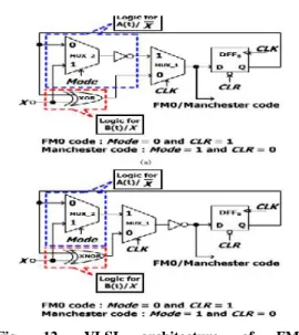
Subsequently, the multiplexer in Fig. 11(b) can be completely spared, and its capacity can be totally coordinated into the moved DFFB. The proposed VLSI design of FM0/Manchester encoding utilizing SOLS procedure is appeared as a part of Fig. 12(a). Thelogic for A(t)/X incorporates the MUX−2 and an
inverter. Rather, the rationale for B(t)/X just fuses a XOR entryway. In the rationale for A(t)/X, the calculation time of MUX−2 is practically
indistinguishable to that of XOR in the rationale for B(t)/X. Be that as it may, the rationale for A(t)/X additionally joins an inverter in the arrangement of MUX−2. This unbalance calculation time between
A(t)/X and B(t)/X brings about the glitch to MUX−1,
potentially creating the rationale blame on coding. To ease thisunbalanced calculation time, the engineering of the adjust calculation time between A(t)/X and B(t)/X is appeared in Fig. 12(b). The XOR in the rationale for B(t)/X is converted into the XNOR with an inverter, and afterward this inverter is imparted to that of the rationale for A(t)/X. This mutual inverter
is migrated in reverse to the yield of MUX−1. Along
these lines, the rationale calculation time between A(t)/X and B(t)/X is more adjust to each other. The appropriation of FM0 or Manchestercode relies on upon Mode and CLR. Furthermore, the CLR additionally has another individual capacity of an equipment introduction. In the event that the CLR is basically inferred by modifying Mode without doling out an individual CLR control flag, this prompts to a contention between the coding mode determination and the equipment instatement. To stay away from this contention, both Mode and CLR are thought to be independently allotted to this plan from a framework controller. Whether FM0 or Manchester code is received, no rationale segment of the proposed VLSI design is squandered. Each part is dynamic in both FM0 and Manchester encodings. In this manner, the HUR of the proposed VLSI engineering is extraordinarily moved forward.
The Differential Manchester Coding
Fig. 12. VLSI architecture of FM0 and Manchesterencodings using SOLStechnique. (a) Unbalance computation time between A(t)/X and
B(t)/X.(b) Balance computation time between A(t)/X and B(t)/X.
Differential Manchester encoding has the accompanying focal points over some other line codes:
A move is ensured at any rate once every piece, permitting the accepting gadget to perform clock recuperation identifying moves is regularly less blunder inclined than contrasting against an edge in a loud environment.Unlike with Manchester encoding, just the nearness of a move is vital, not the extremity. Differential coding plans will work precisely the same if the flag is upset (wires swapped). (Other line codes with this property incorporate NRZI, bipolar encoding, coded check reversal, and MLT-3 encoding).If the high and low flag levels have a similar voltage with inverse extremity, coded signals have zero normal DC voltage, along these lines decreasing the essential transmitting power and minimizing the measure of electromagnetic clamor delivered by the transmission line.
These positive components are accomplished to the detriment of multiplying clock recurrence - the image rate is double the bitrate of the first flag. Every piece period is partitioned into two half-periods: clock and information. The clock half-period dependably starts with a move from low to high or from high to low. The information half-period makes a move for one esteem and no move for the other esteem. One
makes a move for 1 and no move for 0. Accordingly, if a "1" is spoken to by one move, then a "0" is spoken to by two moves and the other way around, making Differential Manchester a type of recurrence move keying. Either code can be deciphered with the clock half-period either beforeor after the information half-period.
Fig. 12.Illustration of differential Manchester coding
Fig13. Differential Manchester Encoder
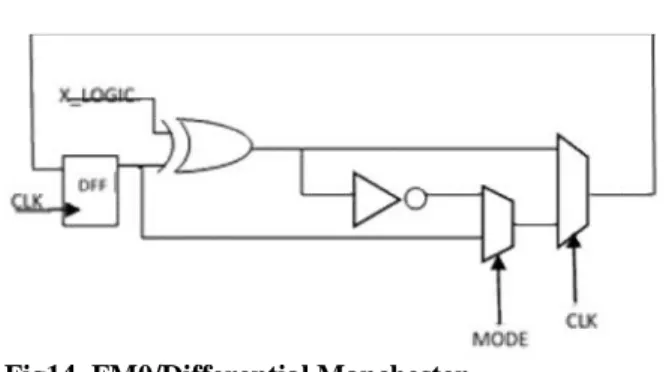
As discussed earlier, the differential Manchester guarantees at least one transition per cycle, in the middle of cycle i.e. when clock changes from 1 to 0 and a transition also occurs at the starting of the cycle i.e. when clock changes from 0 to 1 when the input is 0 and no change when input is 1. Fig13 presents the diagram of the Differential Manchester encoder. If x_logic is 1, XOR gate inverts the output from the previous cycle and passes through the mux and its inverted version is outputted in the second half of the clock cycle as clock changes polarity and if x_logic is 0 at the starting of the cycle, the output of the flip flop passes without change through the XOR gate and is outputted through the mux and inverted version is passed in the second half of the clock cycle. The corresponding simulation result is presented in Fig. 17
DFF
CLK CLK
Fig14. FM0/Differential Manchester
The area reduced implementation of FM0/Differential Manchester is presented in Figure 14. The Mode input to the Mux selects between FM0 and Differential Manchester encodings. The total transistor Count is 92. 72 transistors are required for FM0 and 72 for Differential Manchester and the combined implementation of Fig 14 contains 92 transistors. Area improvement is (144-98)/98 = 47%
and it’s a big leap over the area improvement of the previous work (FM0/ Manchester) which is (84-72)/72 =16%
V. CONCLUSION
The coding-diversity between FM0 and Manchester encodings causes the limitation on hardware utilization of VLSI architecture design. A limitation
Fig 15. Manchester code
Fig 16. FM0_code
Fig 17. Differential Manchester code
Fig 18.fm0/differential Manchester when mode is 1.
Working like a differential Manchester.
Fig.19fm0/differential Macnchester when mode is 0
working like a fm0 hardware.
analysis on hardware utilization of FM0 and Manchester encodings is discussed in detail. In this paper, the fully reused VLSI architecture using SOLS technique for both FM0 and Manchester encodings isproposed. The SOLS technique eliminates the limita-tion on hardware utilization by two core techniques: area-compact retiming and balance logic-operation sharing. The area-compact retiming relocates the hardware resource to reduce 22 transistors. The balance logic-operation sharing efficiently combines FM0 and Manchester encodings with the identical logic components. Differential Manchester encoding is discussed in the paper and The Area improvement ratio for FM0/Differential Manchester is 47% as compared to 16% for FM0/Manchester.
VI. REFRENCES
[1] F. Ahmed-Zaid, F. Bai, S. Bai, C. Basnayake, B. Bellur, S. Brovold, et al., “Vehicle safety
communications—Applications (VSC-A) final
report,” U.S. Dept. Trans., Nat. Highway Traffic
Safety Admin., Washington, DC, USA, Rep. DOT HS 810 591, Sep. 2011.
States,” Proc. IEEE, vol. 99, no. 7, pp. 1162–1182, Jul. 2011.
[3] J. Daniel, V. Taliwal, A. Meier, W. Holfelder, and R. Herrtwich,“Design of 5.9 GHz DSRC-based
vehicular safety communication,” IEEE Wireless Commun. Mag., vol. 13, no. 5, pp. 36–43, Oct. 2006.
[4] P. Benabes, A. Gauthier, and J. Oksman, “A Manchester code generator running at 1 GHz,” in Proc. IEEE, Int. Conf. Electron., Circuits Syst., vol.
3. Dec. 2003, pp. 1156–1159.
[5] A. Karagounis, A. Polyzos, B. Kotsos, and N.
Assimakis, “A 90nm Manchester code generator with CMOS switches running at 2.4 GHz and 5 GHz,” in Proc. 16th Int. Conf. Syst., Signals Image Process.,Jun. 2009, pp. 1–4.
[6] Y.-C. Hung, M.-M. Kuo, C.-K. Tung, and S.-H.
Shieh, “High-speed CMOS chip design for
Manchester and Miller encoder,” in Proc. Intell.Inf. Hiding Multimedia Signal Process., Sep. 2009, pp.
538–541.
[7] M. A. Khan, M. Sharma, and P. R.
Brahmanandha, “FSM based Manchester encoder for UHF RFID tag emulator,” in Proc. Int. Conf. Comput., Commun. Netw., Dec. 2008, pp. 1–6. [8] M. A. Khan, M. Sharma, and P. R.
Brahmanandha, “FSM based FM0 and Miller encoder for UHF RFID tag emulator,” in Proc. IEEE Adv.
Comput. Conf., Mar. 2009, pp. 1317–1322.
[9] J.-H. Deng, F.-C. Hsiao, and Y.-H. Lin, “Top
down design of joint MODEM and CODEC detection schemes for DSRC coded-FSK systems over high
mobility fading channels,” in Proc. Adv. Commun. Technol.Jan. 2013, pp. 98–103.
[10] I.-M. Liu, T.-H. Liu, H. Zhou, and A. Aziz,
“Simultaneous PTLbuffer insertion and sizing for minimizing Elmore delay,” in Proc. Int. Workshop Logic Synth., May 1998, pp. 162–168.
B.MOUNICA (P.G.STUDENT) Studying M.Tech VLSISD in Kakinada Institute of Engineering and Technology, Korangi.She was awarded B.Tech degree in Electronics and Communication Enginering from V.S.Lakshmi Engineering College For Women,Matlapalem.
N.G.N.Prasad received the