A New Optimal Voltage Control Technique For UPS System
Kadimi.sowjanya1, Y Srinivasa Rao2M.Tech Student, Department of EEE, KIET-II, Kakinada, India.1 Asst. Professor, Department of EEE, KIET-II, Kakinada, India.2 Abstract- This paper proposes a simple best possible
voltage control technique for three-stage uninterruptible-control supply frameworks. The proposed voltage controller is made out of an input control term and a repaying control term. The previous term is intended to make the framework errors focalize to zero, while the last term is connected to make up for the framework vulnerabilities. In addition, the ideal load current observer is utilized to enhance cost of the system and reliability. Especially, the closed loop security of a observer based ideal voltage control law is scientifically demonstrated by demonstrating that the entire conditions of the enlarged observer based control framework errors exponentially join to zero. Dissimilar to past algorithm, the proposed strategy can make a tradeoff between control input extent and following error by just picking appropriate performance indexes. The viability of the proposed controller is approved through recreations on MATLAB/Simulink .Finally, the relative outcomes for the proposed conspire and the customary input linearization control plot and a fuzzy logic controller are exhibited to show that the proposed calculation accomplishes a great execution, for example, quick transient reaction, little enduring state error, and low aggregate harmonic distortion under load step change, uneven load, and nonlinear load with the parameter variations.
Index Terms— Optimal load current observer, optimal voltage control, three-phase inverter, total harmonic distortion (THD), uninterruptible power supply (UPS).
INTRODUCTION
UNINTERRUPTIBLE power supply (UPS) systems supply emergency power in case of utility power failures. Recently, the importance of the UPS systems has been intensified more and more due to the increase of sensitive and critical applications such as communication systems, medical equipment, semiconductor manufacturing systems, and data processing systems [1]–[3]. These applications require clean power and high reliability regardless of the electric power failures and distorted utility supply voltage. Thus, the performance of the UPS systems is usually evaluated in terms of the total
harmonic distortion (THD) of the output voltage and the transient/steady state responses regardless of the load conditions: load step change, linear load, and nonlinear load [4]–[7]. To improve the aforementioned performance indexes, a number of control algorithms have been proposed such as proportional–integral (PI) control, H∞
loop-shaping control, model predictive control, deadbeat control, sliding-mode control, repetitive control, adaptive control, and feedback linearization control (FLC). The conventional PI control suggested in [8] and [9] is easy to implement; however, the THD value of the output voltage is not low under a nonlinear-load condition.[10],H∞ loop-shaping control scheme is described and implemented on a single-phase inverter, which has a simple structure and is robust against model uncertainties. A model predictive control method for UPS applications is described in [11]. By using a load current observer in place of current sensors, the authors claimed a reduced system cost. However, the simulation and experimental results do not reveal an exceptional performance in terms of THD and steady-state error. In [12], the deadbeat control method uses the state feedback information to compensate for the voltage drop across t he inductor. However, this method exhibits sensitivity to parameter mismatches, and the harmonics of the inverter output voltage are not very well compensated. In [13] and [14], t he sliding-mode control technique reflects robustness t o t he system noise, and still, the control system has a well-known chattering problem. I n [15], repetitive control is applied t o achieve a high-quality sinusoidal output voltage of a three-phase UPS system.
Generally, t his control technique has a s low response time. In [16], t he adaptive control method with low THD is proposed; nevertheless, there is still a risk of divergence if the controller gains are not properly selected. Multivariable FLC is presented in [17]. I n t his control technique, the nonlinearity of the system i s considered to achieve low THD under nonlinear load. However, it is not easy to carry, out due to the computation complexities. As a result, the aforementioned linear controllers are simple, but t he performance is not satisfactory under nonlinear load. In contrast, t he nonlinear controllers have an outstanding
A New Optimal Voltage Control Technique For UPS System
Kadimi.sowjanya1, Y Srinivasa Rao2
M.Tech Student, Department of EEE, KIET-II, Kakinada, India.1 Asst. Professor, Department of EEE, KIET-II, Kakinada, India.2 Abstract- This paper proposes a simple best possible
voltage control technique for three-stage uninterruptible-control supply frameworks. The proposed voltage controller is made out of an input control term and a repaying control term. The previous term is intended to make the framework errors focalize to zero, while the last term is connected to make up for the framework vulnerabilities. In addition, the ideal load current observer is utilized to enhance cost of the system and reliability. Especially, the closed loop security of a observer based ideal voltage control law is scientifically demonstrated by demonstrating that the entire conditions of the enlarged observer based control framework errors exponentially join to zero. Dissimilar to past algorithm, the proposed strategy can make a tradeoff between control input extent and following error by just picking appropriate performance indexes. The viability of the proposed controller is approved through recreations on MATLAB/Simulink .Finally, the relative outcomes for the proposed conspire and the customary input linearization control plot and a fuzzy logic controller are exhibited to show that the proposed calculation accomplishes a great execution, for example, quick transient reaction, little enduring state error, and low aggregate harmonic distortion under load step change, uneven load, and nonlinear load with the parameter variations.
Index Terms— Optimal load current observer, optimal voltage control, three-phase inverter, total harmonic distortion (THD), uninterruptible power supply (UPS).
INTRODUCTION
UNINTERRUPTIBLE power supply (UPS) systems supply emergency power in case of utility power failures. Recently, the importance of the UPS systems has been intensified more and more due to the increase of sensitive and critical applications such as communication systems, medical equipment, semiconductor manufacturing systems, and data processing systems [1]–[3]. These applications require clean power and high reliability regardless of the electric power failures and distorted utility supply voltage. Thus, the performance of the UPS systems is usually evaluated in terms of the total
harmonic distortion (THD) of the output voltage and the transient/steady state responses regardless of the load conditions: load step change, linear load, and nonlinear load [4]–[7]. To improve the aforementioned performance indexes, a number of control algorithms have been proposed such as proportional–integral (PI) control, H∞
loop-shaping control, model predictive control, deadbeat control, sliding-mode control, repetitive control, adaptive control, and feedback linearization control (FLC). The conventional PI control suggested in [8] and [9] is easy to implement; however, the THD value of the output voltage is not low under a nonlinear-load condition.[10],H∞ loop-shaping control scheme is described and implemented on a single-phase inverter, which has a simple structure and is robust against model uncertainties. A model predictive control method for UPS applications is described in [11]. By using a load current observer in place of current sensors, the authors claimed a reduced system cost. However, the simulation and experimental results do not reveal an exceptional performance in terms of THD and steady-state error. In [12], the deadbeat control method uses the state feedback information to compensate for the voltage drop across t he inductor. However, this method exhibits sensitivity to parameter mismatches, and the harmonics of the inverter output voltage are not very well compensated. In [13] and [14], t he sliding-mode control technique reflects robustness t o t he system noise, and still, the control system has a well-known chattering problem. I n [15], repetitive control is applied t o achieve a high-quality sinusoidal output voltage of a three-phase UPS system.
performance, but t he implementation is not easy due to the relatively complicated controllers.
So far, the optimal control theory has been researched in various fields such as aerospace, economics, physics, and so on [18], since it has a computable solution called a performance
index t hat can quantitatively evaluate t he system performance by contrast with other control theories. In addition, the optimal control design gives the optimality
of the controller according
to a quadratic performance criterion and enables the control system to have good properties such as enough gain and phase margin, robustness t o uncertainties, good tolerance of nonlinearities, etc. [19]. Hence, a linear optimal controller has not only a simple structure in comparison with other controllers but also a remarkable control performance similar t o other nonlinear controllers [20]–[22].
Therefore, this paper proposes an observer- based optimal voltage control scheme f or three-phase UPS systems. This proposed voltage controller encapsulates two main parts: a feedback control term and a compensating control term. The former term is designed to make the system errors converge to zero, and the latter term i s applied t o estimate t he system uncertainties. The Lyapunov theorem is used to analyze the stability of the system. Specially, t his paper proves t he closed loop stability of an observer- based optimal voltage control law by showing that the system errors exponentially converge t o zero. Moreover, the proposed control l aw can be systematically designed taking into consideration a tradeoff between control input magnitude and tracking error unlike previous algorithms [23]. The efficacy of t he proposed control method is verified via simulations on MATLAB/Simulink.
In this paper, a conventional FLC method in [17] and a fuzzy controller is selected to demonstrate the comparative results because it has a good performance under a nonlinear-load condition, and its circuit model of a three-phase inverter in [17] is similar to our system model. Finally, t he results clearly show that the proposed scheme has a good voltage regulation capability such as fast transient behavior, s mall steady-state error, and low THD under various load conditions such as load step change, unbalanced load, and nonlinear load in the existence of the parameter variations.
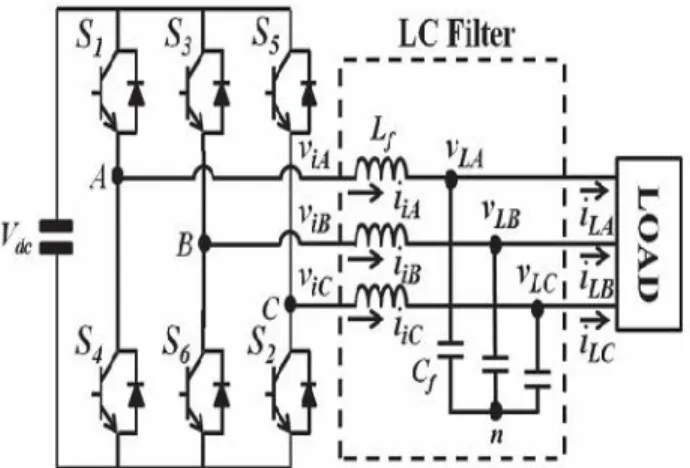
Fig 1. Three-phase inverter with an L C filter for a UPS system.
II. SYSTEM DESCRIPTION AND PROBLEM FORMULATION
The three-phase UPS system with an LC filter is shown in Fig. 1, which is composed of a dc-link voltage (Vdc), a three phase pulse width modulation (PWM) inverter (S1 ∼S6), an output LC filter (Lf, Cf), and a three-phase load
(e.g., linear or nonlinear load). Based on Fig. 1, the dynamic model of a three-phase inverter can be derived in a d− qsynchronous reference frame as follows [24]:
where k1 = 1/Cf, and k2 = 1/Lf. In system model (1), vLd,
vLq, iid, and iiq are the state variables, and vid and viq are
the control inputs. In this scheme, the assumption is made to construct the optimal voltage controller and optimal
load current observer as:
1) The load currents (iLd and iLq) are unknown and vary very slowly during the sampling period [11]
.
III. PROPOSED OPTIMAL VOLTAGE CONTROLLER
DESIGN AND STABILITY ANALYSIS
Here, a simple optimal voltage controller is proposed for system (1). First, let us define the d− q-axis inverter
current references (i∗id, i∗iq) as
Therefore, system model (1) can be transformed into the following error dynamics:
dq =−vLd∗+ (1/k2)ωiLq, and dq =−vLq∗+ (1/k2)ωiLd. Note that ud is applied to compensate for the system uncertainties as a compensating term. Consider the following Riccati equation for the solution matrix P [25]: where Q and R are the positive definite weighting matrices with sufficient dimensions.
Remark 1: Recall that Q and R are the weighting matrices
[26]. Excessive large error or control input values can be penalized by using properly chosen Q and R. Generally, the large Q means a high control performance, whereas the large R means a small input magnitude. Consequently, there is a tradeoff between Q and R in the control system. The Q and R parameters generally need to be tuned until satisfactory control results are obtained. Let the diagonal matrices Q and R be defined as
where Q and R have positive diagonal entries such that
√Qi=1/yimax, where i = 1, 2, . . . , m, and√Ri= 1/umaxi
, where i = 1, 2, . . . , m. The number yimax is the maximally acceptable deviation value for the ith
component of output y. The other quantity umaxi is the
ith component of input u. With an initial guessed value,
the diagonal entries of Q and R can be adjusted through a trial-and-error method. Then, the optimal voltage controller can be designed by the following equation:
where K =−R−1BTP denotes the gain matrix, and ud and
Kx represent a feedforward control term and a feedback
control term, respectively.
Remark 2: The proposed voltage controller, in essence, is
designed based on the well-known linear quadratic regulator minimizing the following performance index [27]:
where x is the error, un = u + ud, and Q and R are symmetrical positive definite matrices as mentioned above.
Fig2: Block diagram of the optimal voltage control
scheme .
B. Stability Analysis of Voltage Controller
Consider the following Lyapunov function:
This implies that x exponentially converges to zero.
Remark 3: By considering the parameter variations, the
state-dependent coefficient matrix A is rewritten as A = A +ΔA, where ΔA means the value of system parameter variations. Thus, (4) can be transformed into the following error dynamics:
The new time derivative of (8) is given by the following:
By (5), (11) is reduced to
If the following inequality holds for the givenΔA:
then V <˙ 0 for all nonzero x. Therefore, the proposed
optimal voltage control system can tolerate any parameter variation satisfying (13).
IV. OPTIMAL LOAD CURRENT OBSERVER DESIGN
AND STABILITY ANALYSIS A. Optimal Load Current Observer Design
As seen in (2) and (4), the inverter current references (i∗d
and i∗ q) and feedforward control term (ud) need load
current information as inputs. To avoid using current
sensors, a linear
optimal load current observer is introduced in this algorithm. From (1) and the assumption, the following dynamic model is obtained to estimate the load current:
Then, the load current observer is expressed as
where xˆ 0 = [ˆiLdˆiLq vˆLd vˆLq] T, and ˆiLd and xˆLq
are estimates of iLd and iLq, respectively. In addition, L is an observer gain matrix calculated by
and Po is the solution of the following Riccati equation:
where Qo and Ro are the positive definite weighting matrices with sufficient dimensions. The manner of choosing Qo and Ro is the same as in Remark 1.
Remark 4: The fourth-order Kalman–Bucy optimal observer [19] is used to minimize the performance index
E(xTe xe), where xe = xo − xˆ o, representing the
estimation values of xTe xe for the following perturbed model:
where d∈R4 and v∈R2 are independent white Gaussian
noise signals with E(d) = 0, E(v) = 0, E(ddT) = Qo, and
E(vvT) = Ro.
B. Stability Analysis of Load Current Observer The error dynamics of the load current observer can be obtained as follows:
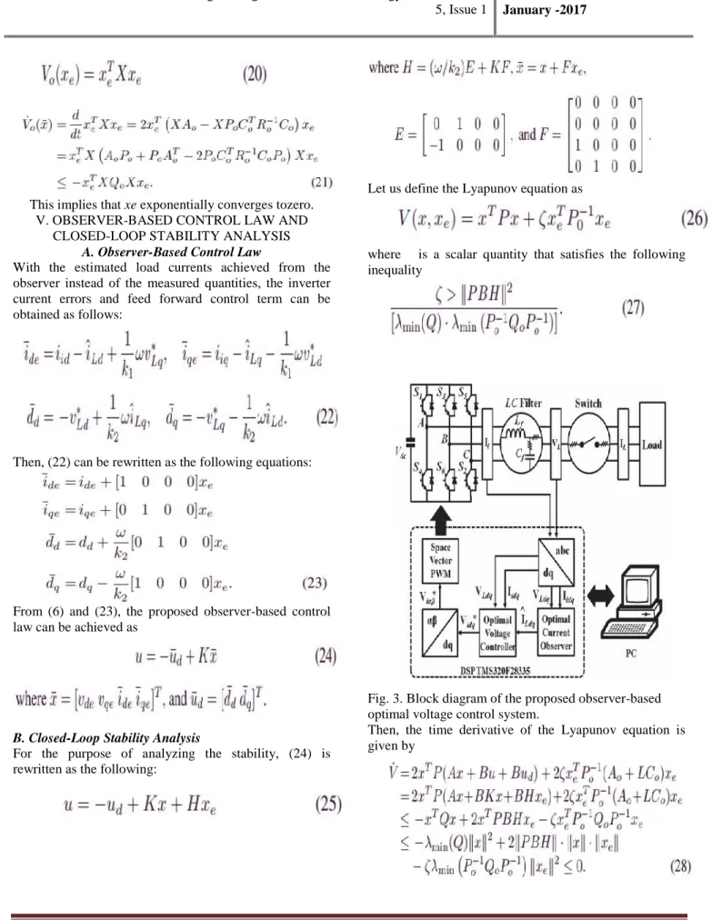
This implies that xe exponentially converges tozero. V. OBSERVER-BASED CONTROL LAW AND
CLOSED-LOOP STABILITY ANALYSIS A. Observer-Based Control Law
With the estimated load currents achieved from the observer instead of the measured quantities, the inverter current errors and feed forward control term can be obtained as follows:
Then, (22) can be rewritten as the following equations:
From (6) and (23), the proposed observer-based control law can be achieved as
B. Closed-Loop Stability Analysis
For the purpose of analyzing the stability, (24) is rewritten as the following:
Let us define the Lyapunov equation as
where ζ is a scalar quantity that satisfies the following inequality
Fig. 3. Block diagram of the proposed observer-based optimal voltage control system.
This implies that x and xe exponentially go to zero. As a result, the design procedure of the proposed observer based control law can be summarized as follows.
Step 1) Build system model (1) in the d− q coordinate frame and then derive error dynamics (4) by using system parameters.
Step 2) Set the optimal voltage controller (6) with the feed forward control term (ud) and feedback control term (Kx).
Step 3) Define the load current estimation model (14) and build the load current observer (15) by using the Kalman– Bucy optimal observer.
Step 4) Select the observer weighting matrices Qo and Ro in Riccati equation by referring to Remark 1. Then, choose the observer gain L in (16) using Qo and Ro.
Fig. 4. Two types of load circuits. (a) Resistive linear load. (b) Nonlinear load with a three-phase
diode rectifier. VI. Fuzzy controller
The word Fuzzy means ambiguity. Fluffiness happens when the limit of snippet of data is not obvious. In 1965 Lotfi A. Zahed propounded the fuzzy set hypothesis. Fuzzy set hypothesis displays massive potential for successful unraveling of the vulnerability in the issue. Fuzzy set hypothesis is a great numerical apparatus to deal with the instability emerging because of unclearness. Understanding human discourse and perceiving written by hand characters are some normal examples where fluffiness shows.
Fuzzy set hypothesis is an augmentation of established set hypothesis where components have differing degrees of participation. Fuzzy logic utilizes the entire interim in the vicinity of 0 and 1 to depict human thinking. In FLC the information factors are mapped by sets of participation capacities and these are called as "Fuzzy SETS".
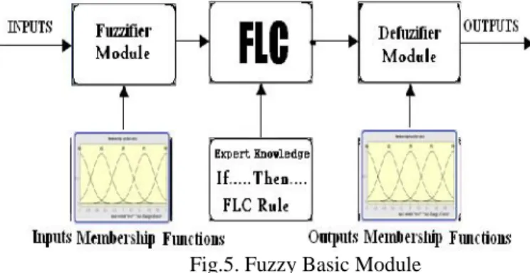
Fuzzy set involves from a participation capacity which could be characterizes by parameters. The incentive in the vicinity of 0 and 1 uncovers a level of enrollment to the fuzzy set. The way toward changing over the fresh contribution to a fuzzy esteem is called as "fuzzificaton." The yield of the Fuzzier module is interfaced with the standards. The essential operation of FLC is built from fuzzy control rules using the estimations of fuzzy sets as a rule for the mistake and the change of blunder and control activity. Essential fuzzy module is appeared in fig.6.
The outcomes are joined to give a fresh yield controlling the yield variable and this procedure is called as "DEFUZZIFICATION."
Fig.5. Fuzzy Basic Module Fuzzy rules:
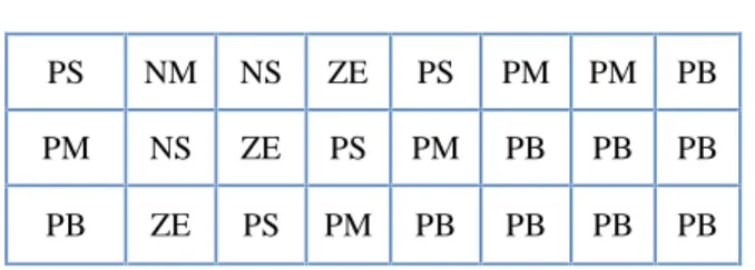
In the fuzzy control, input and output variables are the size of the form to describe in words, so to select special vocabulary to describe these variables, generally used in "big, medium and small" Three words to express the controller input and output variables state, plus the positive and negative directions, and zero, a total of seven words : { negative big, negative medium, negative small, zero, positive small, middle, CT } , the general terms used in the English abbreviation prefix : {NB , NM, NS , ZE, PS , PM, PB}.
COE E
NB NM NS ZE PS PM PB
NB NB NB NB NB NM NS ZE
NM NB NB NB NM NS ZE PS
NS NB NM NS NS ZE PS PM
PS NM NS ZE PS PM PM PB
PM NS ZE PS PM PB PB PB
PB ZE PS PM PB PB PB PB
VII.SIMULINK MODELLING AND RESULTS
Fig 6:Simulink block diagram and control block diagram The proposed voltage control algorithm is carried out in various conditions (i.e., load step change, unbalanced load, and nonlinear load) to impeccably expose its merits. In order to instantly engage and disengage the load during a transient condition, the on–off switch is employed as shown in Fig. 3.The resistive load depicted in Fig. 4(a) is applied under both theload step change condition (i.e., 0%–100%) and the unbalanced load condition (i.e., phase
B opened) to test the robustness of the proposed scheme
when the load is suddenly disconnected. In practical applications, the most common tolerance variations of the filter inductance (Lf ) and filter capacitance (Cf ), which are used as an output filter, are within ±10%. To further justify the robustness under parameter variations, a 30% reduction in both Lf and Cf is assumed under all load
conditions such as load step change, unbalanced load, and nonlinear load. Fig. 7 shows the simulation results of the proposed control method during the load step change. Moreover, Fig. 8 presents the comparative results obtained by employing the conventional FLC scheme under the same condition. Specifically, the figures display the load voltages (First waveform: VL), load currents (Second waveform: IL), and phase A load current error (Third waveform: ieLA = iLA −ˆI LA). It is important to
note that the load current error wave form ,in the results of the conventional FLC method is not included because the FLC scheme does not need load current information. It can be observed in Fig. 5 that when the load is suddenly changed, the load output voltage presents little distortion. However, it quickly returns to a steady-state condition in 1.0 ms.
Fig7:Simulation l results of the proposed observer based optimal voltage control scheme under load step change with −30% parameter variations in Lf and Cf (i.e., balanced resistive load: 0%–100%)—First: Load output voltages (VL), Second: Load output currents (IL), Third: Phase A load current error (ieLA = iLA−ˆiLA).
(a) Simulation. .
Fig8:Simulation results of the proposed observer based optimal voltage control scheme under unbalanced load with−30% parameter variations in Lf and Cf (i.e., phase
Third: Phase A load current error (ieLA = iLA−ˆiLA).
Fig9:Simulation results of the proposed observer based optimal voltage control scheme under nonlinear load with
−30% parameter variations in Lf and Cf (i.e., three-phase diode rectifier)—First: Load output voltages (VL), Second: Load output currents (IL), Third: Phase A load current error (ieLA = iLA−ˆiLA).
Fig10:Simulation l results of the conventional FLC scheme under load step change with −30% parameter variations in Lf and Cf (i.e., balanced resistive load: 0%– 100%)—First: Load output voltages (VL), Second: Load output currents (IL). (a) Simulation.
Fig11:Simulation results of the conventional FLC scheme under unbalanced load with −30% parameter variations in Lf and Cf (i.e., phase B opened)—First: Load output voltages (VL),
Second: Load output currents (IL).
Fig12:Simulation and experimental results of the conventional FLC scheme under nonlinear load with
−30% parameter variations in Lf and Cf (i.e., three-phase diode rectifier)—First: Load output voltages (VL),Second: Load output currents (IL).
VIII. CONCLUSION
This paper has proposed a simple observer-based optimal voltage control method of the three-phase UPS systems The proposed controller is composed of a feedback control term to stabilize the error dynamics of the system and a compensating control term to estimate the system uncertainties. Moreover, the optimal load current observer was used to optimize system cost and reliability. This paper proved the closed-loop stability of an observer-based optimal voltage controller by using the Lyapunov theory. Furthermore, the proposed voltage control law can be methodically designed taking into account a tradeoff between control input magnitude and tracking error unlike previous algorithms. The superior performance of the proposed control system was demonstrated through simulation by implementation of fuzzy controller.. Under three load conditions (load step change, unbalanced load, and nonlinear load), the proposed control scheme revealed a better voltage tracking performance such as lower THD, smaller steady-state error, and faster transient response than the conventional FLC scheme even if there exist
parameter variations. REFERENCES
[1] Eun-Kyung Kim, Francis Mwasilu, Han Ho Choi,
Member, IEEE, and Jin-Woo Jung, Member, IEEE” An Observer-Based Optimal Voltage Control Scheme for Three-Phase UPS Systems”IEEE TRANSACTIONS ON INDUSTRIAL ELECTRONICS, VOL. 62, NO. 4, APRIL 2015
[2] A. Nasiri, “Digital control of three-phase series-parallel uninterruptible power supply systems,” IEEE Trans. Power Electron., vol. 22, no. 4, pp. 1116–1127, Jul. 2007.
[4] A. Mokhtarpour, H. A. Shayanfar, M. Bathaee, and M. R. Banaei, “Control of a single phase unified power quality conditioner-distributed generation based input output feedback linearization,” J. Elect. Eng. Technol.,
vol. 8, no. 6, pp. 1352–1364, Nov. 2013.
[5] J. H. Lee, H. G. Jeong, and K. B. Lee, “Performance improvement of grid connected inverter systems under unbalanced and distorted grid voltage by using a PR controller,”J. Elect. Eng. Technol., vol. 7, no. 6, pp. 918– 925,
Nov. 2012.
[6] H. K. Kang, C. H. Yoo, I. Y. Chung, D. J. Won, and S. I. Moon, “Intelligent coordination method of multiple distributed resources for harmonic current compensation in a microgrid,”J. Elect. Eng. Technol., vol. 7, no. 6, pp.
834–844, Nov. 2012.
[7] C. Salim, B. M. Toufik, and G. Amar, “Harmonic current compensation based on three-phase three-level shunt active filter using fuzzy logic current controller,”J. Elect. Eng. Technol., vol. 6, no. 5, pp. 595–604, Sep. 2011.
[8] U. Borup, P. N. Enjeti, and F. Blaabjerg, “A new space-vector-based control method for UPS systems powering nonlinear and unbalanced loads,” IEEE Trans. Ind. Appl., vol. 37, no. 6, pp. 1864–1870, Nov./Dec. 2001.
[9] H. Karimi, A. Yazdani, and R. Iravani, “Robust control of an autonomous four-wire electronically-coupled distributed generation unit,” IEEE Trans. Power Del., vol. 26, no. 1, pp. 455–466, Jan. 2011.
[10] T. S.Lee, S. J. Chiang, and J. M. Chang, “H∞ loop-shaping controller designs for the single-phase UPS inverters,” IEEE Trans. Power Electron., vol. 16, no. 4,
pp. 473–481, Jul. 2001.