Synchronization of Grid Connected PV System Using PI Controller
P BhogiRajuPG Scholar B V C Engineering College
Odalarevu [email protected]
A Ramakrishna Assistant Professor B V C Engineering College
Odalarevu
Abstract
Grid connected solar system consists of converters Circuits are organized in two different ways one is DC/DC boosters and another is PWM Inverter. This combination results decrement of Quality and efficiency of electric power, this paper reflects the use of a single phase 13- level photo voltaic (PV) inverter in solar system connected to grid with a pulse width-modulated (PWM) control system. The rapid variations in radiation can be remunerated by Digital proportional-integral controller. This inverter gives a less harmonic distortion and significant power factor over five level inverters and is examined and experimented through simulation.
Index Terms—Grid connected, photovoltaic (PV), proportional–integral (PI) current control.
1. Introduction
The drastic usage of energy consumed by the people in various purpose leads to increase the importance of sustainable energy sources from the past two decades. Because of scarcities of fossil fuel the renewable energy sources like wind energy and solar energy are attracting the attention of scientist for advancement in power electronics techniques. Especially Solar electric energy became most popular because of advisement in manufacturing technologies and cost advantages [1]
The three common topologies for multilevel inverters are as follows: 1) diode clamped (neutral clamped) [9]–[11]; 2) capacitor clamped (flying capacitors) [12]–[14] and 3) cascaded H-bridge inverter [15]–[17].
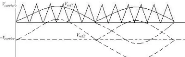
Fig.1 Carrier and Reference Signals.
1.1 13-Level Inverter Topology and PWM law
The proposed single-phase 13-level inverter topology is shown in Fig. 3. The inverter adopts a full-bridge configuration with an auxiliary circuit [4]. PV arrays are connected to the inverter via a dc–dc boost converter. Because the proposed inverter is used in a grid-connected PV system, utility grid is used instead of load. The DC–DC boost converter is used to step up inverter output voltage Vinv to be more than 1.414 of grid voltage Vg to ensure power flow from the PV arrays into the grid [19]. A filtering inductance Lf is used to filter the current injected into the grid. The injected current must be sinusoidal with low harmonic distortion. In order to generate sinusoidal current, sinusoidal PWM is used because it is one of the most effective methods. Sinusoidal PWM is obtained by comparing a high-frequency carrier with a low-frequency sinusoid, which is the modulating or reference signal. The carrier has a constant period; therefore, the switches have constant switching frequency. The switching instant is determined from the crossing of the carrier and the modulating signal.
A. Sinusoidal PWM Law
is taken to be volt–seconds, as shown in Fig.4, i.e., As1=Ap1 and As2 = Ap2. One of these pulses, the
general kthpulse, is characterized in detail in Fig.5. where Mis the “modulation index” and
M = Vm/Vs(21)
Equation (21) can be expressed in terms of amplitude of carrier signal Vc by replacing Vs with Vc. Because, in this topology, two identical reference signals are used, Vs=2Vc and Vm =Vref1 = Vref2.
If M >1, higher harmonics in the phase waveform are obtained. Therefore, M is maintained between zero and one. If the amplitude of the reference signal is increased to be higher
than the amplitude of the carrier signal, i.e., M >1, this will lead to over modulation. Large values of M in sinusoidal PWM techniques lead to full over modulation [20]. Fig.4 shows the carrier and reference signals for different values of M. Equations (19) and (20) define the modulation law, which is more
Fig. 2. Carrier and reference signals for different values of modulation index M >1
Commonly expressed in terms of δ1k and δ2k, by substituting from (7) and (9) to give
δ1k=δ0[1 +M sin(αk-δ0)] (22)
δ2k=δ0[1 +M sin(αk+δ0)]
(23)
Thus, the switching anglesδ1k and δ2k for the kth pulse can be calculated from (22) and (23) in terms of modulation index M and angles αk andδ0 which depend upon the fundamental frequency and frequency ratio.
B. Harmonic Spectrum of Sinusoidal PWM Waveform
The voltage harmonics produced by the sinusoidal PWM can be computed by first calculating the harmonics due to the kth pulse alone, Ank, and then summating the harmonic contributions of all p pulses
Fig.3. Ideal 13-level inverter output voltage Vinv.
2. Operational Principle of the Proposed Inverter Because PV arrays are used as input voltage sources, the voltage produced by the arrays is known as Varrays. Varrays is boosted by a DC–DC boost
converter to exceed √2Vg. The voltage across the DC-bus capacitors is known as Vpv. The operational principle of the proposed inverter is to generate 13-level output voltage, i.e., zero, +1/12 Vdc, +1/6 Vdc,
+1/4 Vdc, +1/3 Vdc, +5/12 Vdc, +1/2 Vdc,-1/2Vdc,
-5/12Vdc, -1/3Vdc, -1/4Vdc, -1/6Vdc, and -1/12Vdc
-supply dc voltage as in Fig.5. As shown in Fig.2, an auxiliary circuit which consists of four diodes and a switch S1 is used between the dc-bus capacitors and the full-bridge inverter. Proper switching control of the auxiliary circuit can generate half level of PV supply voltage, i.e., +Vpv/2 and -Vpv/2 [4]. Two
reference signals Vref1 and Vref2 will take turns to be compared with the carrier signal at a time. If Vref1
exceeds the peak amplitude of the carrier signal Vcarrier, Vref2will be compared with the carrier signal
until it reaches zero. At this point onward, Vref1takes
over the comparison process until it exceeds Vcarrier.
This will lead to a switching pattern. Switches S1–S7 will be switching at the rate of the carrier signal frequency, whereas S4 and S9 will operate at a
frequency equivalent to the fundamental frequency.
3. Control System Implementation
The feedback controller used in this application utilizes the PI controller. As shown in Fig. 6. the current injected into the grid, also known as grid current Ig, is sensed and fed back to a comparator which compares it with the reference current Iref . Iref is obtained by sensing the grid voltage and converting it to reference current and multiplying it with constant m. This is to ensure that Ig is in phase with grid voltage Vg and always at near-unity power factor.
maximum power point tracking (MPPT) method which has quick-response characteristics and is able to make good use of the electric power generated in any weather, is needed to solve the aforementioned problem [21]. Various MPPT control methods have been discussed in detail in [22]. Constant m is derived from the MPPT algorithm. The perturb-and-observe algorithm is used to extract maximum power from PV arrays and deliver it to the inverter [23],[24]. The instantaneous current error is fed to a PI controller. The integral term in the PI controller improves the tracking by reducing the instantaneous error between the reference and the actual current. The resulting error signal u which forms Vref1 and Vref2 is compared with a triangular carrier signal, and intersections are sought to produce PWM signals for the inverter switches.
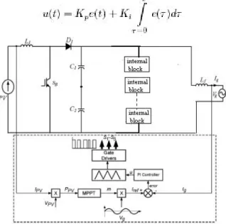
Fig. 4 . 13-level inverter with PI controller where
u(t) control signal; e(t) error signal;
t continuous-time-domain time variable;
τcalculus variable of integration; Kp proportional-mode control gain; Ki integral-mode control gain.
Implementing this algorithm using a DSP requires one to transform it into the discrete-time domain. Trapezoidal sum approximation is used to transform the integral term into the discrete-time domain because it is the most straightforward technique. The proportional term is directly used without approximation.
Fig.5 Block Diagram of PI controller To eliminate the need to calculate the full summation at each time step (which would require an ever-increasing amount of computation as time goes on), the summation is expressed as a running sum
sum(k) =sum(k - 1) + [e(k) + e(k - 1)] (33) u(k) =Kpe(k) + K_isum(k). (34) These two equations, which represent the discrete-time PI control law, are implemented in control the overall operation of the inverter.
Control signal saturation and integral-mode anti windup limiting are easily implemented.. In this work, the control signal itself takes the form of PWM outputs from the Pi controller. Therefore, the control signal is saturated at the value that corresponds to 100% duty cycle for the PWM. An undesirable side effect of saturating the controller output is the integral-mode windup. When the control output saturates, the integral-mode control term (i.e., the summation) will continue to increase but will not produce a corresponding increase in controller output (and hence will not produce any additional increase in plant response). The integral can become quite large, and it can take a long time before the controller is able to reduce it once the error signal changes sign. The effects of windup on the closed-loop output are larger transient overshoot and undershoot and longer settling times. One approach for overcoming the integral-mode windup is to simply limit in pi controller the maximum absolute value allowed for the integral, independent of the controller output saturation [25], as shown in Fig.4.
Fig.6. PWM switching strategy
Fig.7. Inverter 13-level output voltage for M=0.2
Fig.8. Inverter 13-level output voltage for M=0.8
Fig.9. Inverter 13-level output voltage for M=1.2
Fig.10. Inverter 13-level output current for M=0.2
Fig.11. Inverter 13-level output current for M=1.2
Fig.14. Inverter 13-level output current for M=0.8
A. Simulation Results
- 14 shows Vinv and Ig for different values of M. The dc-bus voltage is set at 400 V (>√2Vg; in this case, Vg is 240 V) in order to inject current into the grid. Fig. 9 shows that Vinv is less than √2Vg due toM being less than 0.5.
Fig.12. THD of 5-level Current wave form at M= 0.8
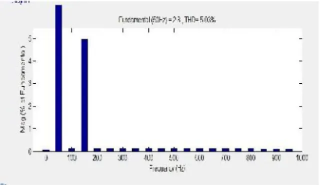
Fig.13. THD of 13-level Current wave form at M=0.8
The inverter should not operate at this condition because the current will be injected from the grid into the inverter, rather than the PV system injecting the current into the grid, as shown in Fig. 12. Over modulation condition, which happens when M >1.0, is shown in Fig. 13. It has a flat top at the peak of the positive and negative cycles because both the reference signals exceed the maximum amplitude of the carrier signal. This will cause Ig to have a flat portion at the peak of the sine waveform, as shown in Fig. 14. To optimize the power transferred from PV arrays to the grid, it is recommended to operate at 0.5 < M < 1.0. Vinv and Ig for optimal operating condition. As shown in fig.10,13. Ig is almost a pure
sine wave; the THD can be reduced compared with that under other values of M. To analyze the performance of the PI current control scheme, a sudden step change is applied to the simulation process. This step change is similar to real-time environment condition (for example, the sun is emerging from the clouds).
level THD 5-level 5.07% 13-level 3.84%
5. Conclusion
This paper presented a single-phase 13 level inverter for synchronized grid pv system. It utilizes two reference signals and a carrier signals to generate PWM switching signals. The circuit topology, modulation law, and operational principle of the proposed inverter were analyzed in detail. The pi controller Is to optimize the operation of inverter. Simulation results indicate that the THD of the 13-level inverter is much lesser than that of the conventional 5- level never. Furthermore, both the grid voltage and the grid current are in phase at near-unity power factor.
6. References
[1]. J. M. Carrasco, L. G. Franquelo, J. T. Bialasiewicz, E. Galvan,R. C. PortilloGuisado, M. A. M. Prats, J. I. Leon, and
N.Moreno-Alfonso,“Power-electronic systems for the grid integration of renewable energy sources: A
survey,”IEEE Trans. Ind. Electron., vol. 53, no. 4, pp. 1002–1016, Aug. 2006.
[2]. V. G. Agelidis, D. M. Baker, W. B. Lawrance, and C. V. Nayar, “A multilevel PWMinverter topology for photovoltaic applications,” in
Proc.IEEE ISIE, Guimarães, Portugal, 1997, pp. 589–594.
[3]. S. Kouro, J. Rebolledo, and J. Rodriguez,
“Reduced switching-frequencymodulation
algorithm for high-power multilevel inverters,”
IEEE Trans. Ind. Electron., vol. 54, no. 5, pp. 2894–2901, Oct. 2007.
[4]. S. J. Park, F. S. Kang, M. H. Lee, and C. U. Kim,
“A new single-phase fivelevel PWM inverter
employing a deadbeat control scheme,” IEEE Trans.Power Electron., vol. 18, no. 18, pp. 831–
[5]. L. M. Tolbert and T. G. Habetler, “Novel
multilevel inverter carrier-based PWM method,”
IEEE Trans. Ind. Appl., vol. 35, no. 5, pp. 1098–
1107, Sep./Oct. 1999.
[6]. M. Calais, L. J. Borle, and V. G. Agelidis,
“Analysis of multicarrier PWM methods for a single-phase five-level inverter,” in Proc. 32nd Annu. IEEE PESC, Jun. 17–21, 2001, vol. 3, pp. 1173–1178.
[7]. N. S. Choi, J. G. Cho, and G. H. Cho, “A general circuit topology of multilevel inverter,” in Proc. 22nd Annu. IEEE PESC, Jun. 24–27, 1991, pp. 96–103.
[8]. G. Carrara, S. Gardella, M. Marchesoni, R.
Salutari, and G. Sciutto, “A new multilevel
PWMmethod: A theoretical analysis,” IEEE
Trans. Power Electron., vol. 7, no. 3, pp. 497–
505, Jul. 1992.
[9]. A. Nabae and H. Akagi, “A new neutral-point
clamped PWM inverter,” IEEE Trans. Ind.
Appl., vol. IA-17, no. 5, pp. 518–523, Sep./Oct. 1981.
[10]. J. Pou, R. Pindado, and D. Boroyevich,
“Voltage-balance limits in fourlevel
diode-clamped converters with passive front ends,”
IEEE Trans. Ind. Electron., vol. 52, no. 1, pp. 190–196, Feb. 2005.
[11]. S. Alepuz, S. Busquets-Monge, J. Bordonau, J. Gago, D. Gonzalez, and J. Balcells,
“Interfacing renewable energy sources to the
utility grid using a three-level inverter,” IEEE Trans. Ind. Electron., vol. 53, no. 5, pp. 1504–
1511, Oct. 2006.
[12]. T. Meynard and H. Foch, “Multi-level
choppers for high voltage applications,” Eur. Power Electron. J., vol. 2, no. 1, pp. 45–50, Mar. 1992.
[13]. D.-W. Kang, B.-K. Lee, J.-H. Jeon, T.-J. Kim, and D.-S. Hyun, “A symmetric carrier
technique of CRPWM for voltage balance
method of flying capacitor multilevel inverter,”
IEEE Trans. Ind. Electron., vol. 52, no. 3, pp. 879–888, Jun. 2005.
[14]. B.-R. Lin and C.-H. Huang,
“Implementation of a three-phase
capacitorclamped active power filter under unbalanced condition,” IEEE Trans. Ind. Electron., vol. 53, no. 5, pp. 1621–1630, Oct. 2006.
[15]. M. Marchesoni, M. Mazzucchelli, and S.
Tenconi, “A non conventional power converter
for plasma stabilization,” in Proc. IEEE Power Electron. Spec. Conf., 1988, pp. 122–129. [16]. J. Rodriguez, P. Hammond, J. Pontt, R.
Musalem, P. Lezana, and M. Escobar,
“Operation of a medium-voltage drive under
faulty conditions,” IEEE Trans. Ind. Electron., vol. 52, no. 4, pp. 1080–1085, Aug. 2005. [17]. X. Kou, K. Corzine, and M. Wielebski,
“Overdistention operation of cascaded multilevel
inverters,”IEEE Trans. Ind. Appl., vol. 42, no. 3, pp. 817–824, May/Jun. 2006.
[18]. J. Rodriguez, J.-S. Lai, and F. Z. Peng,
“Multicarrier PWM strategies for multilevel inverters,” IEEE Trans. Ind. Electron., vol. 49, no. 4, pp. 724–738, Aug. 2002.
[19]. M. Calais, V. G. Agelidis, and M. S.
Dymond, “A cascaded inverter for
transformerless single phase grid-connected
photovoltaic systems,” inProc. 31st Annu. IEEE PESC, Jun. 18–23, 2001, vol. 3, pp. 1173–1178. [20]. M. H. Rashid, Power Electronics: Circuits,
Devices, and Applications, 3rd ed. Englewood Cliffs, NJ: Prentice-Hall, 2004.
[21]. N. Mutoh and T. Inoue, “A control method
to charge series-connected ultraelectric double-layer capacitors suitable for photovoltaic generation systems combining MPPT control
method,”IEEE Trans. Ind. Electron., vol. 54, no. 1, pp. 374–383, Feb. 2007.
[22]. T. Esram and P. L. Chapman, “Comparison
of photovoltaic rray maximum power point
tracking techniques,” IEEE Trans. Energy
Convers.,vol. 22, no. 2, pp. 439–449, Jun. 2007. [23]. N. Femia, G. Petrone, G. Spagnuolo, and M.
Vitelli, “Optimizing dutycycle perturbation of P&O MPPT technique,” in Proc. 35th Annu. IEEE PESC, Jun. 20–25, 2004, vol. 3, pp. 1939–
1944.
[24]. X. Liu and L. A. C. Lopes, “An improved
perturbation and observation maximum power
point tracking algorithm for PV arrays,” inProc. IEEE 35th Annu. PESC, Jun. 20–25, 2004, vol. 3, pp. 2005–2010.