International Journal of Science Engineering and Advance Technology,
IJSEAT, Vol 2, Issue 10, October - 2014 ISSN 2321-6905
Direct Torque Control for Matrix Converter Driven PMSM
B Prakash Yellamelli *, P.Sailesh Babu*, Dr.K. Satyanarayana*
Departement of Electrical and Electronics Engineering, Pragati Engineering College, Surampalem [email protected],[email protected],[email protected]
ABSTRACT
This paper carries work on application of direct torque control for Five-Phase permanent magnet synchronous motor drives. In recent years, only voltage source inverters (VSIs) have been used to supply five-phase drives, but Matrix converters (MCs) pose many advantages over conventional VSIs, such as lack of dc bulk capacitors, high quality power output waveform and higher number of output voltages. Due to some special applications of multiphase machines such as ship propulsion and aerospace, the volume of these drives is an important challenging problem. In this paper, direct torque control (DTC) algorithm using a three-to-five phase Matrix Converter is proposed for five-phase permanent magnet synchronous motors (PMSMs). Because of higher number of output voltages in MCs, there is a greater degree of freedom to control the torque and flux. In other words, this proposed method use the advantages of both DTC method and MCs. Simulation results show the effectiveness of presented method.
Keywords -
DTC, matrix converter, five-phase PMSM, Switching VectorI.
INTRODUCTION
Permanent magnet machines have been used in the last three decades. They appear in several different stator and rotor structures and can be used in almost all kinds of application where traditional machines are used. Their main features and advantages are : higher efficiency, high torque/volume relationship. Unfortunately, some of these advantages refer only to machines built with high energy magnets, which are still expensive, despite the introduction of new materials and improved production techniques[1]. This feature has restricted the use of permanent magnet machines built with rare earth magnets to applications where cost is of secondary concern High phase number drives possess several advantages over conventional three phase drives such as: reducing the amplitude and increasing the frequency of torque pulsations, reducing the rotor harmonic currents, reducing the current per
phase without increasing the voltage per phase, lowering the dc link current harmonics and higher reliability Since adjustable speed AC drives application requires a power electronic converter for their supply, the number of machine phases is essentially unlimited in drive applications . this has led to an increase in interest in multiphase AC drives applications[4] , especially in conjunction with traction , and ship propulsion .The first proposal for using a five phase induction motor drive system dates back to 1969[16] . Multiphase machines are therefore often considered for and applied in high power applications .The main driving forces behind this accelerated development have been three specific application areas, namely ship propulsion, “more-electric” aircraft, and traction (railway, electric vehicles, and hybrid electric vehicles).source inverters (VSIs), in the literatures related to the multiphase motor drives, only VSIs have been used to feed these motors.
In this paper, a new DTC of five-phase PMSM using three-to-five phase matrix converter is proposed. Input power factor is controlled to be kept close to unit. In the other word, the advantages of both DTC scheme and MC are used in this presented method. All of output voltage vectors of a three-to-five phase MC are obtained and the effects of these vectors on torque and flux variations are investigated and also a proper switching table is proposed. Simulation results show that using this presented switching pattern table, besides the control of input power factor, good and precise control in electromagnetic torque and flux is achieved.
II.
BASIC DIRECT TORQUE FOR
FIVE-PHASE PERMANENT MAGNET
SYNCHRONOUS MOTOR
controlling the switching sequence of the inverter transistors. Figure 3 shows the DTC for a PMSM block diagram. It can be seen that once one has the estimated and reference instantaneous values of electromagnetic torque and stator flux, we proceed to calculate the error between them; these errors are used as inputs for the hysteresis controllers, which aim to maintain the torque and flux errors within upper and lower limits allowed, so that when evaluating within these limits an output level is obtained to know the status of the variable. The output levels achieved in this stage of the control are input signals to the block that is responsible for finding the right vector to get rid of the speed error. This procedure is made for each sampling instant to drive the PMSM to the desired speed value[6]. Five-phase VSI inherently produce 32 output voltage space vectors with two zero vectors and thirty active voltage vectors as it shown in Figure 2. In a five phase system there are two orthogonal subspaces namely D−Q subspace and
−
subspaces which are shown in Figure 3. As can be seen in this figure, these 32 voltage vectors are composed of three sets of different amplitudes namely small, medium and large vectors, respectively[7]. From the following equation, the output voltage vectors in D−Q and
−
subspaces are obtained. If the upper switches of converter are closed, S is considered to be 1 and on contrary, if the lower switches are closed, S is 0.
e
S
e
S
e
S
e
S
S
V
V
E jj D j C j B A dc Q D
5 2 5
4 5
4 5
2
0
5 2
(1)
Fig 1. Five-phase voltage source inverter
The principle of selecting a voltage space vector in the conventional DTC of five-phase drive is similar as that in DTC of three-phase drives. It is shown in [7] that, for three-phase PMSM with uniform air gap, electromagnetic torque is
sin1 2 3
max t
L p
s r e
T
(2)
Where,
| ( )|
presents the amplitude of stator flux,is explanatory of rotor flux permanent magnet, p is the number of poles and δ is angle between stator flux and rotor flux.
For a five-phase motor equation (2) can be rewritten as
sin1 2 5
t L
p
Q sD Q rD e
T
(3)
As it is shown in Figure 2, the switching pattern plane is divided to ten sectors. Each voltage vector has a radial component and a tangential component. The variation of radial component is related to stator flux variation and the variation of tangential component is related to variation of electromagnetic torque
According to aforementioned analysis, a switching table has been proposed in [10] which is shown in table.1. It should be noted that, dϕ=−1(dϕ= 1 ), show that the stator flux linkage has to be decreased (increased). On the other hand, dTe =−1(dTe = 1) is the explanatory of this fact that the electromagnetic torque has to be decreased (increased).
Fig 2. Thirty two voltage vector of a five-phase VSI
switching state will be selected from an offline switching table and command will be sent to the inverter.
Electromagnetic torque and stator flux are obtained using stator voltages and currents in stationary reference frame. Stator flux angle also can be achieved using equation (6).
i
i
T
e ds qs qs dsp
2 2 5 (4)
V
R
sI
dta
V
R
I
dts
(5)
2 2 s
g
t s 1
(7)
(6)Where, α is the direct axis and β is the perpendicular axis.
III.
DIRECT TORQUE CONTROL
USING MATRIX CONVERTER
Three-phase to Five-phase Matrix Converter
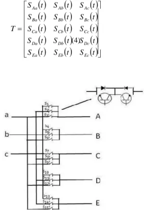
The power circuit topology of a three-phase to five-phase matrix converter is illustrated in Figure.4. As can be seen, there are five legs which each leg have three bidirectional switches in series[3].
Switching constraint is
S
ka
S
kb
S
kc
1
.Where, k = {A, B, C, D, E} is the output phase of the converter and j = {a,b,c}is the input phase of the converter, S is the status of switches which 1 denotes that the switch is closed and 0 implies that the switch is open.
Fig 3. DTC of five-phase PMSM using standard VSI
The state of converter can be represented using following transformation matrix.
t S t S t S t S t S t S t S t S t S t S t S t S t S t S t S T Ec Eb Ea Dc Db Da Cc Cb Ca Bc Bb Ba Ac Ab AaFig 4. Schematic diagram of a three-phase to five-phase
matrix converterUsing transformation matrix, we will
obtain
V0(t)TVi(t) (8)
Ti(t)TTI0(t)
Where, Voand Ioare output voltage and output
current vectors, respectively. Also, Vi and Ii are input
voltage and input current vectors.
phases are connected to a same input phase, zero voltage vectors will be produced[11]. As it has been mentioned in previous sections, using medium and small vectors in D−Q plane, leads to large harmonics in stator current. Thus, in this paper authors only will use large voltage vectors of D−Q subspace.
The space vector of output voltages can be expressed as follow
5
2 5 4 5 4 5 2 0 5 2 j E j D j C j B
A V e V e V e V e
V V
(10)
Where VA,VB,VC,VDand VEare output line-to-neutral
voltage vectors of five phase A,B ,C ,D and E , respectively.
In the same way, the space vector of input currents can be expressed as follow
3 2 3 23
2
j c j b ai
i
i
e
i
e
I
(11) Where ia, iband icare input line currents.
The switching states of a 3x5MC are shown in table 2. It should be noted that, only the large vectors of MC are shown in this table. The medium and small voltage space vectors are shown in tables A and B.
The block diagram of proposed DTC scheme is shown in Figure5. As it can be seen, the basis of this proposed DTC algorithm is as same as classical DTC. But, in each sampling period, in addition to measuring stator voltage and currents, voltage and currents of input side of MC should be measured to specify the sector that input line-to-neutral voltage vector lies in. Also, the current and voltage angle difference is measured and is sent to controller. Controller imposes this displacement angle to be close to zero. Thus, a close to unity input power factor will be obtained.
Figure 5: Schematic diagram of proposed DTC using
matrix converter
IV.
SIMULATION RESULTS AND
DISCUSSION
The models of the PMSM, VSI and basic DTC algorithm are developed in Matlab/Simulink in order to examine the complete behavior of the basic DTC. In comparison with basic model, matrix converter driven PMSM was considered with DTC methodology. Various tests have been carried out in order to investigate the drive performance and to characterize the steady-state and transient behavior. The parameters of motor are P=4, d-axis Inductance is 18mH, q-axis
inductance is 42mH, Inertia 0.025 Kgm2
,
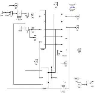
Stator Resistance 0.7 ohmsFigure 6:Simulink model of proposed system
Figure 7:Simulink model for matrix converter
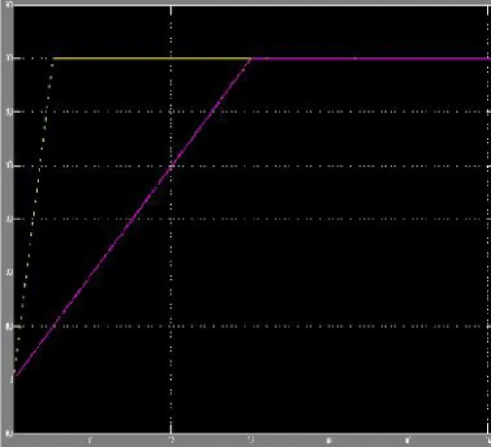
Figure 8:Reference torque and load torque for classical DTC
Figure 9:Reference speed and machine speed for classical DTC
Figure 10:Filtered current and corresponding phase voltage for classical DTC
Figure.8, Figure.9 and Figure.10 show the
characteristics of electromagnetic torque, speed , stator
current and corresponding phase voltage for classic
DTC in rotor speed of 600 rpm respectively. As it is
shown in these figures, in classic DTC method
electromagnetic torque and stator flux follow their
references slowly. Stator current is distorted because of
large magnitude of third harmonic currents. The
command torque changes from 7 N.m to 2 N.m at 0.2
sec, from 2 N.m to -2 N.m at 0.4 sec,from 2 N.m to
-7 N.m at 0.6 sec, from --7 N.m to -7 N.m at 0.8 sec .the
load torque is following the command torque slowly
and it has an high over shoots and undershoot, high
settling time for every command torque change Filtered
input line current and its corresponding line-to-neutral
voltage are shown in Figure.10.
Figure 11:.1laod torque and reference torque for matrix converter based DTC
Figure 13:Filtered current and corresponding phase voltage for matrix converter based DTC
Figure.11, Figure12 and Figure.13 show the
characteristics of electromagnetic torque, speed , stator
current and corresponding phase voltage for matrix
converter based DTC in rotor speed of 600 rpm
respectively. As it is shown in these figures, the
command torque changes from 7 N.m to 2 N.m at 0.2
sec, from 2 N.m to -2 N.m at 0.4 sec,from 2 N.m to
-7 N.m at 0.6 sec, from --7 N.m to -7 N.m at 0.8 sec .the
load torque is following the command torque very
effectiveli and it has low over shoots low undershoot,
very good settling time for every command torque
change . Figure.13 shows that the Filtered input line
current and its corresponding line-to-neutral voltage are
very less distorted compared to classical DTC.flux
ripples are less in matrix converter based DTC
compared with classical DTC.
Figure.14 and Figure.14 shows that the stator flux for
matrix converter based DTC and classical DTC
Figure 14:stator flux for matrix converter based DTC
Figure 15:stator flux for classical DTC
V.
CONCLUSION
The control of torque and flux is done through DTC algorithm has been proposed for matrix converter fed five-phase PMSMs. All of output voltage space vectors of a three-to-five phase MC have been extracted. It has been shown that, there are 93 output voltage vectors with fixes directions which can be use in DTC method. Moreover the torque and flux control, the input power factor has been controlled and kept close to unit. The presented method has been simulated, steady state situation, and dynamic performance were verified through results. In all of situation, torque and flux followed their reference values as well as VSI-fed (classic) drives and matrix converter drive were verified for input power factor improvement .all the simulation results shows that the matrix converter based DTC shows better results than classical DTC in terms of low ripple content in load torque, less distorted in phase current and corresponding phase voltage.
REFERENCES
[1] Rohan M.Ingle, Dr.S.B.Bodkhe. Multiphase
Permanent Magnet Synchronous Motor Drive—A
Comparative Study. IJERA, ICLAC, ISSN:2248-9622
April 2014.
[2] E. Levi, R. Bojoi, F. Profumo, H.A. Toliyat. S.
Williamson, Multiphase induction motor drives—a
technology status review. IEE Elec. Power Appl. 1 (4)
(2007) 489–516.
[3] Thomas Friedli, Johann W.Kolar.Milestones in
Matrix converter Research.in: IEEJ Journal of Industry
[4] L. Parsa, H.A. Toliyat. Five-phase permanent
magnet motor drives for ship propulsion
applications.in: Proc. IEEE Electric Ship Technologies
Symposium, Philadelphia, US, 2005, pp. 371–378.
[5] Azeddine BENDIABDELLAH, Ghanem BACHIR
A Comparative Performance Study Between A Matrix
Converter And A Three-Level Inverter Fed Induction
Motor. Accta Electrotechnica of Informatiion
No.2,Vol.6,2006.
[6] SANDA VICTORINNE PATURCA, MIRCEA
COVRIG, LEONARD MELCESCU. Direct Torque
Control of Permanent Magnet Synchronous Motor
(PMSM) – an approach by using Space Vector
Modulation (SVM)Conf. Rec. WSEAS/IASME, Spain,
Dec2006..
[7] L.Zhong, M.F. Rahman, K.W. Lim. Analysis of
Direct Torque Control in Permanent Magnet
Synchronous Motor Drives. IEEE Trans. Power Elec.
Vol. 12, No. 3, May. 1997, pp. 528-536.
[8] Samir Kouro, Mariusz Malinowski, K.Gopakumar.
Recent Advances and Industrial Applications of
MultilevelConverters.In IEEE Transactions on
Indusrial Electronics, vol.57 No.8, August2010.
[9] Bojoi R, farina F, Griva G, Profumo F, Tenconi A.
Direct torque control for dual three-phase induction
motor drives. IEEE Trans IndAppl 2005;41(6):627–
1636.
[10] P.Chlebis, P.Simonik, and M.Kabasta. The
Comparison of Direct and Indirect Matrix Converters.
PIERS Proceedings. USA. Appl., vol. 43,no. 4,
pp.310-314, Jul. 2010.
[11] P. Wheeler, J. Rodriguez, J. Clare, L.Empringham,
and A. Weinstein. Matrix converters: A technology
review. IEEE Trans. Ind. Electron., vol. 49, no. 2, pp.
276–288, Apr. 2002.
[12] P. Wheeler, J. Clare, M. Apap, and K. J. Bradley.
Harmonic loss due to operation of induction machines
from matrix converters. IEEE Trans. Ind. Electron.,
vol. 55, no. 2, pp. 809–816, Feb. 2008.
[13] Djahbar, B. Mazari. Performances Evaluation of
Two-Motor Drive with Matrix Converter Supply and
Series Connection of Stator Windings. IREE 2010; V0l:
5(4); pp. 1504-1511.
[14] D. Casadei, G. Serra, and A. Tani. The use of
matrix converters in direct torque control of induction
machines. IEEE Trans. Ind. Electron., vol. 48, no. 6,
pp. 1057–1064, Dec. 2001.
[15] C. Ortega, A. Arias, C. Caruana, J. Balcells, and
M. Asher. Improved Waveform Quality in the Direct
TorqueControl of Matrix-Converter-Fed PMSM
Drives. IEEE Trans. Ind. Electron., Vol. 57, no. 6, pp.