DYNAMIC PARTICLE SYSTEMS FOR OBJECT STRUCTURE
EXTRACTION
O
LIVIERL
AVIALLE1,2, F
RANCKA
NGELLA1, C
HRISTIANG
ERMAIN1,2 ANDP
IERREB
AYLOU11Equipe Signal/Image ENSEIRB - University of Bordeaux I BP 99, 33402 Talence Cedex, 2ENITA de
Bordeaux, BP 201, 33175 Gradignan cedex - France e-mail: [email protected]
(Accepted February 2, 2003)
ABSTRACT
A new deformable model based on the use of a particle system is introduced. By defining thelocal behavior of each particle, the system behaves as an active contour model showing a variable topology and regularization properties. The efficiency of the particle system is illustrated by two applications: the first one concerns the use of the system as a skeleton extractor based on the propagation of particles inside a tree-shaped object. Using this method, it is possible to generate a cartography of structures such as veins or channels. In a second illustration, the system avoids the problem of initialization of a piecewise cubic B-spline network used to straighten curved text lines.
Keywords: deformable models, particle system, snakes, structure extraction.
INTRODUCTION
Deformable models have been widely used since the original definition of snakes or active contours (Kass et al., 1988). Most developments of deformable models deal with boundary detection and feature extraction in 2-D or 3-D images (Cohen, 1991). Basically, the method consists in deforming and moving an initial curve toward a region of interest. The solution is obtained by minimizing the model energy.
The inability to change from a given topology to another is a major drawback of classical deformable models. For this reason, several approaches have been proposed. Topologically adaptable snakes analyse the curve-topology (Mc Inerney and Terzopoulos, 1995) or the surface-topology (Mc Inerney and Terzopoulos, 1997), and include cutting or fusion steps during the evolution. Level set methods consider the curve or the surface as zero values of a higher dimension object (Sethian, 1996). Implicit models act the same way but are generated from predefined primitives (Yahia et al., 1998). A special class of deformable models is represented by particle systems (Szeliski and Tonnesen, 1992) allowing topology changes during the evolution, and providing results involving predefined primitives, as opposed to level set methods.
The next section presents a deformable model based on the definition of a particle system (Angella et al., 1998). This model overcomes classical deformable model drawbacks. The particle system shows the ability
to change its topology and unlike the classical models does not require an initialization close to the solution.
Then, we present two applications of this model. First, a classical application consists in propagating the particles inside a grayscale tree-shaped object. The algorithm simulates the evolution of a system subjected to internal, and external forces. The simultaneous use of particle systems and tree generation allows to extract a linear piecewise, and connected skeleton of the object. The second application concerns the straightening of text lines (Lavialle et al., 2001): the approach considers a piecewise cubic B-spline system where each curve is defined as a particle. The system propagates in the vertical direction from a central position. Internal forces control the expansion of the curve system, whereas external forces drive each curve toward a text line to obtain the global structure of the distorted text.
PARTICLE SYSTEM
Model definition
Let us denote by S a particle system. This system is a set of nodes (or particles) Mi. Each node can evolve
Our goal is to encourage the particle system to explore the image. Towards that end, interaction rules between particles have to be defined. A repulsion behavior allows the system to expand; an attractive behavior forces particles not to move away from other particles. Thus, internal forces are defined through the introduction of a Lennard-Jones interaction potential function gathering a long-range attraction term and a short-range repulsion term (Heyes, 1998). Classically, the Lennard-Jones potential describes the interaction between pairs of atoms in a solid or a liquid. It has the following form:
−
=
6 12)
(
r
r
r
ε
σ
σ
φ
, (1)where r is the distance from an atom to an any other atom. The constants ε and σ are important in that they determine the strength and shape of the interaction, hence the properties of the solid or liquid. The force between individual atoms is the negative of the potential gradient.
Herein, we consider the following function:
( )
m nd
A
d
B
d
=
−
ρ
, (2)where d is the distance between two particles. A, B,m
and n are positive coefficients used to set the equilibrium distance. In our application, we chose
m = 2, n = 1 yielding an equilibrium distance equal to 2B/A.
Using ρ, we can compute a global interaction
force int( ,)
i t
f
:∑
∈∇
−
=
) ()
(
) , ( int t i j M ij i td
f
υρ
r
, (3)where υi(t) is the neighborhood of Mi at step t (the
notion of neighborhood will be defined in the next section).
External forces being application-dependent, they will be described (along with additional internal forces) in the next section where two applications are considered.
System evolution
One can control the behavior of each particle Mi
by computing Fi, the total resulting force. Then, if we
consider that each particle is a mechanical system, its
evolution follows the classical Newtonian mechanical relation: i i i F dt t dv
m ⋅ ( ) = , (4)
mi stands for the mass of the particle. For our
purpose, mi is a constant and can be included in
Fi. The numerical integration of this differential
equation is obtained using the Euler integration method. This leads to the choice of a time interval parameter, resulting from a precision/computation time compromise. Then, (4) becomes:
⋅ + = − ⋅ + = − − − t i t i t i t i f i t i t i v t x x v F t v
v ( )
1 1 1 δ α δ , (5)
where t i
x and t i
v are respectively the position and the velocity of a particle Mi at step t. α f is a friction
coefficient added to ensure the stability of the system. Our approach consider the evolution of the system as a solution of a Newtonian mechanical Eq. 4. Another equivalent approach can be proposed by generating all forces from a unique potential function, so that the evolution of the particle system S will be similar to the process involved when minimizing a global energy, as it is performed when dealing with classical active contour (Kass et al., 1988).
APPLICATIONS OF THE MODEL
Object structure extraction
The problem of skeleton extraction has found many solutions based on mathematical morphology algorithms (Serra, 1982). Here, we propose to extract structures in grayscale tree-like objects by using the particle system described above (Angella et al.,1998). The evolution of the system is the consequence of a Lennard-Jones interaction force (Eq. 3) complemented with two other internal forces presented in Angella et al. (1998) within the framework of object structure extraction.
The first one provides the system with learning abilities: this force, inspired by the so-called evolutionary computation domain, acts as ”insect pheromones”, driving particles preferentially to the paths already used by prior particles (Dorigo and Gambardella, 1997). To do so, we build a velocity map Iph using the velocity
v
it of each particle Mi atimage. Then, we define an elementary pheromonal force averaged around
x
it as expressed by Eq. 6:( ) ( )
∑
( )( )
Γ ∈ ∇ ⋅ Γ = t i p p ph t i i, t ph I cardf 1 r , (6)
where t i
x
is the position of Mi at step t andΓ
i(t)is thegiven area around
x
it.The second additional internal force is a regularization force between particles that tends to align particles within the same branch of a given object by attracting a particle to the middle point of its two neighbors. Let us consider a particle
M
i with a neighboring, at step t,ν
it ={
Mj,Mk}
. The force is defined by:
−
−
=
() ) ( ) ( ) , (2
t i t k t j i t regx
x
x
f
, (7)t j
x ,
x
kt andx
it are respectively the position of Mj,k
M
andM
i at step t.As we want our system to lie inside objects, we use an external force depending directly on the gradient of the image I, defined as follows:
(
G
I
)
k
f
ext=
−
ext⋅
∇
r
∇
∗
, (8)I
G∗
∇ is the modulus of a filtered gradient of the image. G is a low pass filter used to extend the influence area of objects boundaries in I. kext is used
to control this influence.
The particle system will evolve inside objects from an initial location xinit where particles are generated with initial velocity vinit. The generation is T-periodic (prior to generating a particle, a test is run to avoid overpopulation within the generating area).
The process described above simulates the evolution of a deformable expansible tree created and modified by linking neighboring particles and cutting branches according to different rules defined below. The evolution of the tree T may be viewed as the joint evolution of the particle system S and a set of links L
between the elements of S.
Updating the tree carries with it the ability to change the topology. In addition, L is involved in the determination of the neighborhoods
ν
it, and then inthe computation of
f
int(t,i)andf
reg(t,i). These neighborhoods are actually necessary to list particles influencing a given particle. In this respect, the algorithm does not rely on the shape of objects but on their structure as expressed by L.We define the set of links L with the binary function: ( )
( )
not if 0 t step at linked are if 1 : it i,j M
l a , (9)
with
l
(t)(
i
,
i
)
=
0
,
∀
i
.Eq. 9 defines the neighborhood of Mi at step t:
{
/ ()( , )=1}
= M l t i j
j t i
ν
. (10)The search for a neighbor of Mi is performed with
respect to the trajectory of Mi and includes time an
space constraints: the neighbor shall be the closest to a previous location of Mi. The entire trajectory of Mi
is accordingly scanned starting at step t down to step 1 using a restricted area around the trajectory. The selected neighbor Mj is obtained using the following
algorithm:
for m=t,…,1:
(
m)
i t k S M k
x
x
j
k−
=
∈ /min
arg
if
(
x
x
m)
D
εi t
j
−
≤
then t
i j
M ∈
ν
breakelse m=m-1 end if
Dε restricts the search process around the
trajectory of Mi and m denotes the current iteration
varying from t down to 1. The process is stopped at iteration m if a neighbor satisfying the proximity condition is found.
− Addition and convergence: when a particle has an empty neighborhood, a neighbor must be found among the other particles using the algorithm above. This situation happens for a newly generated particle or for a particle whose links are cut to remain consistent with the object structure. In addition, the system can hold optional convergence cases, leading to cycle generations, so that the tree becomes a graph including loops.
− Deletion: if a particle Mi moves too far away from
its neighbors, its links must be cut. The deletion process is just based on a deletion distance.
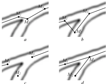
− Divergence and shift: the divergence, or shift behavior, occurs around a junction in the object structure. It is a local reorganization of the set of links. To understand how the tree is updated, let us analyze Fig. 1. In the vicinity of a junction (step a), the particle M2 does not follow the
particle M1, so that at step b the structure of the
links in L does not reflect the structure of the object. At step c, we decide to cut all links to M2
and to suitably reconnect the tree at step d. This topology change is tractable if one finds a criterion to decide when cutting the skeleton at step c. The rule adopted is based on angle comparisons considering that the angle between two links associated to a given particle has to be greater than a fixed minimal angle θjunction. If it is not the case, a junction is detected, the two links
are removed and new links have to be found leading to a topology change.
This simultaneous evolution of S and L allows a hierarchical exploration of the object and overcomes the topology changes problem. Finally, the approach returns a hierarchical, connected, and piecewise linear “skeleton” of the object without any post-processing.
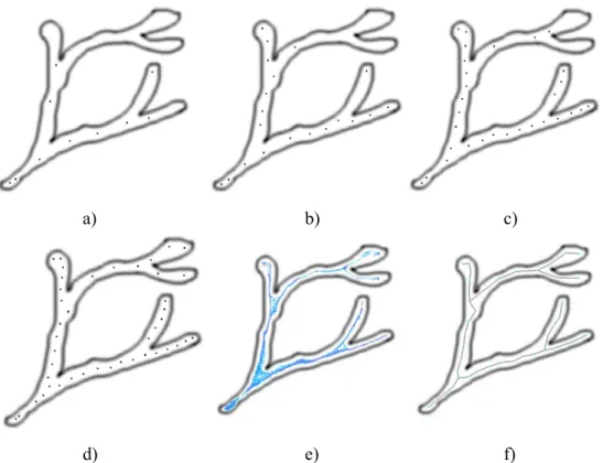
Fig. 2 illustrates the evolution of the system on a synthetic tree-like object. In this case, all particles are generated at the same location with the same initial velocity vector. The tree update process consists in adding, deleting or shifting links according to the geometric relations between the particles and taking the trajectories into account (Angella et al., 1998). In this example, the evolution stops because of the initialization vicinity test.
Fig. 3 shows a result obtained on a more complex image. The simultaneous use of a particle system and tree generation yields the skeleton of the river in an aerial image. The particles are generated from the top-left of the structure and are then allowed to explore the object. Fig. 3a and 3b show the trajectories of the particles and the resulting structure, respectively. Note that some ramifications are not explored: some image areas do not provide the particles with relevant external forces due to a low contrast between the object and its environment. In addition, the object structure may become too thin at the end of a ramification to allow the extension of the system.
a) b) c)
d) e) f)
Fig. 2. Synthetic tree-like object. 2a, 2b, 2c and 2d: Evolution of the particle system. 2e: Particle trajectories. 2f: final tree
a) b)
Fig. 3. Real tree-like object structure extraction. 2a) particle trajectories. 2b) main ramifications of the skeleton for an aerial image.
ACTIVE CONTOURS NETWORK TO
STRAIGHTEN DISTORTED TEXT LINES
We proposed a 2D extension of the system to straighten distorted text (Fig. 4a) (Lavialle et al., 2001). For such a purpose, the system of particles is transformed into a system of curves. A curve is associated to each line of text. Noting k
i
a the kth parameter of a ith curve C
i, our goal is to define an
energy function depending on k i
a . Using a classical approach, each curve may be modeled by Basis
splines (B-splines) (Lehmann et al., 1999). Here, we rather use piecewise cubic B-splines (i.e. each curve is a set of connected cubic B-splines). Let us note Ci a
B-Spline.
a
ik, s is then the kth control point of the sthconnected spline of Ci. The model continuity is
enforced by constraining the control points in order to obtain smoothed curves (Lavialle et al., 2001).
position of the sth spline of C
i. The internal energy is
defined by assuming that the text is locally uniform (i.e. line spacing is constant). Thus, our purpose is to move each curve toward the centre of its two neighbors:
(
,)
21 ,
1 ,
, int
2
1
)
(
=
−
−+
k+s
i s k i sk i s
k
i
a
a
a
E
.(11)
The system evolves along the vertical direction from an initial location. In addition to the internal energy defined above, we introduce an interaction force based on a Lennard-Jones potential between the control points of neighboring curves to force them to move from their initial location.
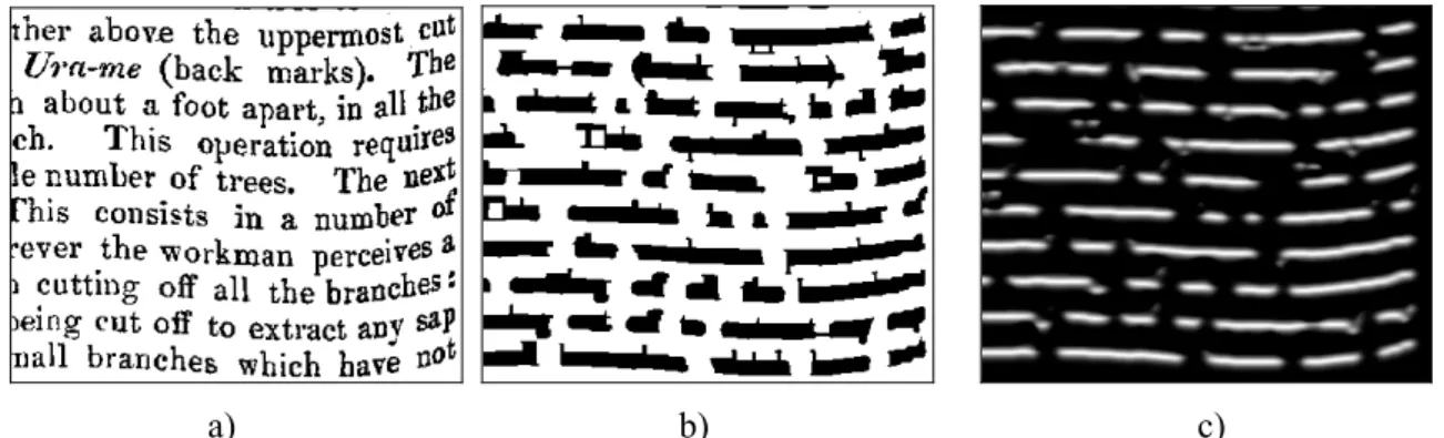
The minimization of an appropriate external energy will allow to attract the curves toward the text. The computation of this energy is based on a mathematical morphology transformation: we first use an opening on the original image to fill in spaces between letters. Fig. 4b shows the result obtained with a structuring element of size 11×5. Then, considering the bottom of the lines, the external energy is computed using a vertical Deriche gradient
(Deriche, 1987). The smoothing resulting from the use of this operator is necessary to extend the influence of the lines, and then to attract the curves toward the solution
Fig. 4c shows the value of the vertical gradient
y
I
∇
. Finding the bottom of the lines is done with a very simple energy functional:E
ext=
−∇
I
y leading to the external force:( )
y extext
k
I
f
=
⋅
∇
r
∇
. (12)All curves are generated at an initial location yinit
with an initial velocity vinit. The evolution of the
system follows the classical mechanical relation described in the previous section.
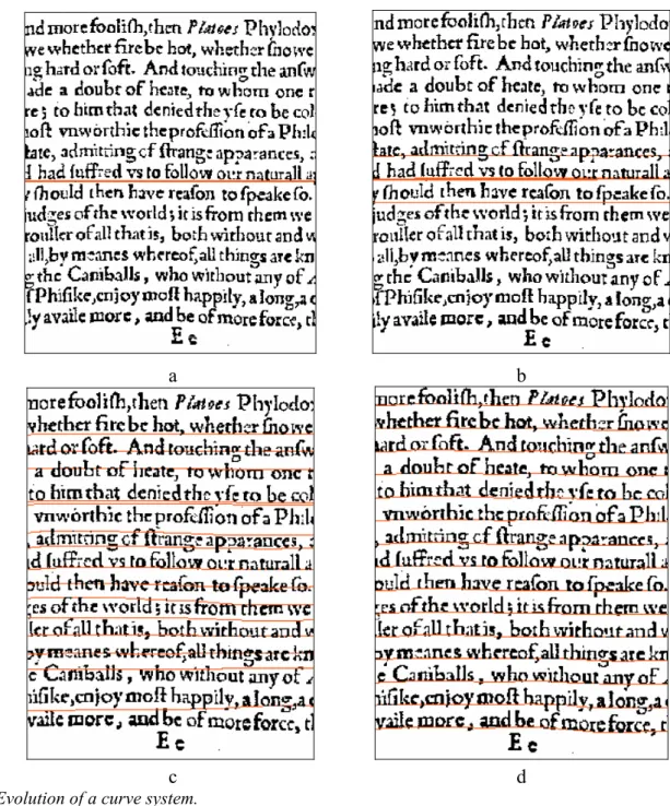
Fig. 5 shows an example of distorted text. Fig. 6 illustrates the evolution of the curve system on a detail of Fig. 5. The curves are initialized at the middle of the page. After 150 iterations, each curve system has converged toward a text line and the straightening is possible (Fig. 7).
a) b) c)
Fig. 4. a) curved text, b) opening of 4a, c) vertical gradient computed from 4a.
a
b
c
d
Fig. 6. Evolution of a curve system.
DISCUSSION
In this paper, we presented a particle system acting as a deformable model with flexible topology and regularization properties. When applied to the extraction of an object structure, the system returns a continuous and piecewise connected skeleton. As the particles first move through large ramifications, the method can give additional information on the hierarchy of structures. We can notice that the 3-D extension of this method is obvious: it has been already successfully tested on synthesized 3-D images.
In the second application, we demonstrated the ability of our method to simplify the initialization step in the case of a system of cubic B-splines used to straighten text lines.
REFERENCES
Angella F, Lavialle O, Baylou P (1998). A deformable and expansible tree for structure recovery. Proccedings IEEE-ICIP 98, Chicago, 1:241-5.
Cohen LD (1991). On active contour models and ballons. CVGIP: Image understanding 53:211-8.
Deriche R (1987). Using canny's criteria to derive a recursively implemented optimal edge detector. Int J on Comput Vision, 167-87.
Dorigo M, Gambardella LM (1997). Ant colony system: a
cooperative learning approach to the traveling salesman problem. IEEE Trans on Evol Comput 1:53-66. Heyes DM (1998). The liquid state: application of
molecular simulations. John Wiley and Sons Ltd. Kass M, Witkin A, Terzopoulos D (1988). Snakes: Active
contour models. Int J Compr Vision 9:321-31.
Lavialle O, Molines X, Angella F, Baylou P (2001). Active contour network to straighten distorted text lines. Proceedings IEEE-ICIP 01, Thessaloniki, 3:748-51 Lehmann TM, Gönner C, Spitzer K (1999). Survey:
Interpolation Methods in Medical Image Processing. IEEE Trans Med Imag 18:1049-75.
Mc Inerney T, Terzopoulos D (1995). Topologically Adaptable Snakes. Proceedings of the 5th International Conference on Computer Vision, Cambridge, 840-5. Mc Inerney T, Terzopoulos D (1997). Medical image
segmentation using topologically adaptable surfaces. Grenoble: CVRM, 23-32.
Serra J (1982). Image analysis and mathematical morphology. Vol 1. Academic Press.
Sethian JA (1996). Level set methods. Evolving interfaces in geometry, fluid mechanics. Computer Vision and Material Science. Cambridge: University Press. Szeliski R, Tonnesen D (1992). Surface modeling with
oriented particle system. Proceedings SIGGRAPH, 26:185-94.