CODE OF PRACTICE
FOR
SITE SUPERVISION
2009
FOREWORD
The Supervision Plan System has been implemented since December 1997 with the issuance of the Technical Memorandum for Supervision Plans (the “Technical Memorandum”) and the Draft Code of Practice for Site Safety Supervision. The Draft Code was refined in November 2000 with some clarification on the principles and requirements and some simplification on the procedures.
Pursuant to the enactment of the Buildings (Amendment) Ordinance 2004, the second edition of the Technical Memorandum and Code of Practice for Site Supervision came into effect on 31 December 2005. The revisions covered inclusion of the requirements for quality supervision and the qualified supervision requirements for geotechnical works, deletion of the details on assessment of degree of complexity and class of supervision, and updating of the qualification and experience requirements for TCP and the additional supervision requirements for critical stages of building works.
With the introduction of the minor works control system and a new register of minor works contractors under the Buildings (Amendment) Ordinance 2008, a new regime to control the carrying out of building works that are designated as minor works is established. This revision covers supervision requirement for the carrying out of minor works and other minor refinements of the Supervision Plan System.
This Code of Practice gives guidance to authorized persons, registered structural engineers, registered geotechnical engineers, registered contractors and other personnel in the building industry for the preparation of supervision plans, carrying out their respective supervision duties and other site supervision matters.
December 2010 Buildings Department
CONTENTS
Paragraph Page
1 Scope 1
2 Interpretation 2
3 Objective and General Principles 2-3
4 Safety Management and 3-16
Responsibilities of Relevant Personnel
5 Typical Items for Specific Tasks by TCPs 17-23
6 Quality Supervision Requirements 24-34
7 Building Works with Significant 34-36
Geotechnical Content
8 Supervision Requirements 37-53
9 More Frequent Supervision Requirements 54-58
10 Communication and Reports 59-60
Appendix I Standard Form of Supervision Plan with 61-69
Annex : Confirmation of Appointment of TCPs
Appendix II Form A : Record of Specific Tasks Performed 70-71
by TCP
Appendix III Form B : Non-conformity and Rectification Reports 72-73
Appendix IV Form C : Calculation Sheet for Combination of 74-75
Appendix V Examples of Calculation Sheet of Combination of 76-81 TCPs
Appendix VI Samples of Checklist and Record of Specific 82-96
Tasks Performed by TCP
Appendix VII Qualifications of Competent Person (Logging) and 97-99
TCPs (GIFW)
Appendix VIII Administrative Procedures for Ground Investigation 100-103
Field Works
Appendix IX Key Records on Quality Supervision of Soil Nailing 104-105
Works
Appendix X TCP Qualifications and Experience Accepted 106-115
during Transitional Period before 22 December 2005 or Accepted pursuant to the Corresponding Recognition and Requirements Prescribed in Paragraph 8 of this Code
1 Scope
1.1 Safety management of building works or street works addresses two types
of supervision:
(a) Quality Supervision
This means ensuring that the building works or street works are carried out in general accordance with the provisions of the Buildings Ordinance and Regulations, and with the plans approved in respect of them by the Building Authority (BA) or the plans submitted to the BA in respect of minor works which are carried out in accordance with the simplified requirements (hereafter called “submitted plans for minor works”), and with any order made or condition imposed, pursuant to any provision of the Ordinance or regulations in that behalf, by the BA; and
(b) Site Safety Supervision
This means controlling hazards from building works or street works so as to minimize the risk to:
(i) the workers on site;
(ii) all persons around the site; and
(iii) adjoining buildings, structures and land.
1.2 The Technical Memorandum for Supervision Plans (the “Technical
Memorandum”) sets out the principles, requirements and operation of supervision plans. This Code of Practice for Site Supervision provides detailed guidance to the practitioners on the application of the Technical Memorandum in the preparation of supervision plans and in the adoption of good practices for site supervision.
1.3 Apart from the Technical Memorandum, reference should also be made to
the Buildings Ordinance, Practice Notes for Authorized Persons, Registered Structural Engineers and Registered Geotechnical Engineers, Practice Notes for Registered Contractors and any other relevant documents issued by the BA.
2 Interpretation
2.1 Unless specified otherwise, the terms and expressions used in this Code
shall have the same meaning assigned to them under the Buildings Ordinance and the Technical Memorandum. Any additional terms and expressions used are explained in the text of this Code.
3 Objective and General Principles
Objective
3.1 This Code sets out and explains :
(a) the procedures for establishing site supervision requirements for
various types of building works or street works;
(b) the deployment of Technically Competent Persons (TCPs) and the
combination of their duties;
(c) the principles of safety management structure within each functional
stream (“stream”) and the responsibilities and duties of the head, representative and TCPs of each stream;
(d) the specific tasks of TCPs in carrying out site supervision;
(e) the division of responsibility for temporary works;
(f) the qualification and experience requirements for each grade of TCP; and
(g) the procedures for dealing with non-conformities.
Principles for Assessing Supervision Requirements
3.2 The site supervision requirements relate to the type of building works or
street works and the scale of the works involved.
3.3 Other than the supervision requirements in accordance with paragraph 3.2,
additional site supervision requirements shall be provided during the critical stages of various types of building works or street works.
3.4 The BA may review and adjust the supervision requirements, taking into
consideration the prevailing state of technology and methods of construction.
3.5 The BA may also review and upgrade the qualifications and experience requirements for the TCPs and adjust their site inspection frequencies in order to further improve the standard of supervision, after taking into consideration their supply in the market.
4 Safety Management and Responsibilities of Relevant Personnel
Safety Management Structure
4.1 The Authorized Person (AP), Registered Structural Engineer (RSE),
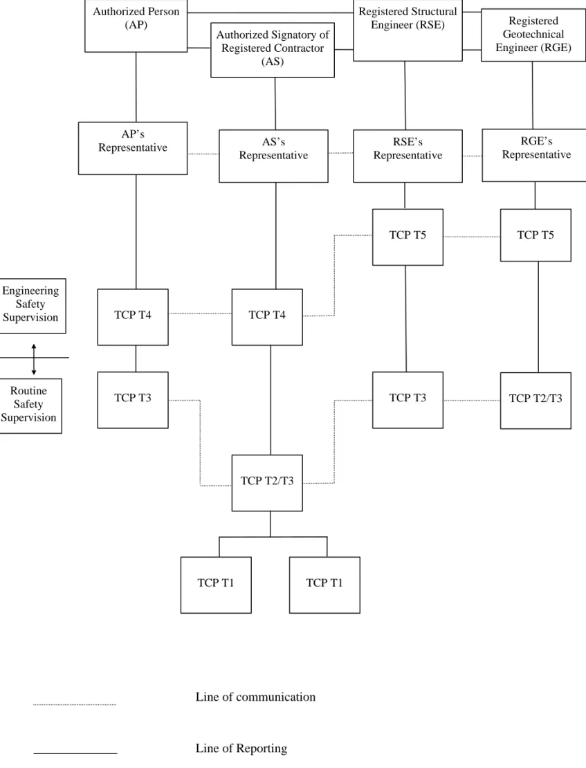
Registered Geotechnical Engineer (RGE) and Authorized Signatory (AS) of the Registered Contractor (RC) are the heads of the safety management structure of the respective functional streams. Other than the head, each of the supervision streams shall consist of a Representative of the head, TCPs responsible for routine safety supervision, i.e. T1 to T3 and TCPs responsible for engineering safety supervision, i.e. T4 to T5 as appropriate for a particular type of works. A Representative shall be the highest grade TCP within their respective stream and shall take the senior role in the management structure. Alternatively, the AP, RSE, RGE and AS may act as the respective representative themselves to carry out such safety management functions (subject to their inspection frequency be not less than that required of the highest grade TCP within their respective stream). A typical example of the safety management structure for a job site is illustrated in Figure 4.1.
Responsibilities of Relevant Personnel
4.2 The head of the management structure shall have overall responsibility and
accountability for their respective functional stream. The Representative is directly accountable to the head (i.e. AP, RSE, RGE or AS, as the case may be), whereas all other safety management personnel are accountable to the head through the Representative. Responsibilities and duties of the heads, Representatives and TCPs regarding the preparation and execution of supervision plans are set out in Tables 4.1 to 4.4.
4.3 The supervision plan, if required to be submitted under the Technical
Memorandum, shall be lodged with the BA by the AP prior to or at the same time as the application for the first consent for commencement of
building works or street works. For minor works carried out according to the simplified requirements, the supervision plans, if required to be submitted under the Technical Memorandum, shall be submitted to the BA not less than 7 days before commencement of the minor works. A standard form of Supervision Plan is set out in Appendix I.
4.4 The AP, RSE, RGE and AS shall also submit the confirmation of
appointment of TCPs as at an Annex to Supervision Plan or within 7 days from the date of commencement of works as indicated in the Form BA10/ notice of commencement of minor works.
4.5 TCPs of higher grades may take up the responsibilities of those of lower
grades and the duties of TCPs may be combined. For combination of the duties of TCPs, reference should be made to paragraphs 8.12 to 8.17.
Authorized Person (AP)
Registered Structural Engineer (RSE) Authorized Signatory of
Registered Contractor (AS)
RSE’s Representative AS’s
Representative AP’s
Representative
TCP T1 TCP T1
TCP T2/T3
TCP T3 TCP T3
TCP T4 TCP T4
TCP T5
Routine Safety Supervision
Engineering Safety Supervision
Registered Geotechnical Engineer (RGE)
RGE’s Representative
TCP T5
TCP T2/T3
Line of communication
Line of Reporting
Table 4.1
Responsibilities and Duties under AP’s Stream
Authorized Person
Responsibilities
Assuming overall responsibilities in the appointment of his
Representative and TCPs.
Ensuring the full implementation of the supervision plan regarding
his own stream.
Overseeing the full implementation of the supervision plan
regarding the RC’s stream.
Establishing an efficient and effective mechanism for dealing with
non-conformities.
Duties
Assessing the scale for each type of works relevant to the project.
Compiling his own part of the supervision plan.
Coordinating and submitting the supervision plan to the BA.
Devising checklists of specific tasks for his TCPs.
Supervising his Representative and TCPs.
Notifying the BA of any non-conformities which pose an imminent
danger, or cause a material concern for safety and the RC fails to rectify.
Carrying out site inspections as necessary.
AP’s Representative
Responsibilities
Accountable to the AP for the implementation of the AP’s
supervision plan.
Representing the AP as the formal point of contact in
communication with other functional streams.
Taking overall responsibility to check on site if the safety
measures required under supervision plans are implemented.
Accountable to the AP for the satisfactory execution of the
specific tasks, and for the responsibilities of junior TCPs including checking of the essential items for specific tasks provided in this Code.
Ensuring that the RC’s safety management structure complies with
Table 4.1 Cont’d
Duties
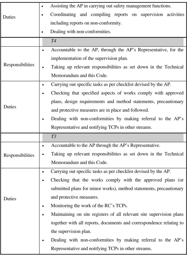
Assisting the AP in carrying out safety management functions.
Coordinating and compiling reports on supervision activities including reports on non-conformity.
Dealing with non-conformities. T4
Accountable to the AP, through the AP’s Representative, for the implementation of the supervision plan.
Taking up relevant responsibilities as set down in the Technical Memorandum and this Code.
Responsibilities
Duties
Carrying out specific tasks as per checklist devised by the AP. Checking that specified aspects of works comply with approved
plans, design requirements and method statements, precautionary and protective measures are in place and followed.
Dealing with non-conformities by making referral to the AP’s Representative and notifying TCPs in other streams.
T3
Responsibilities
Accountable to the AP through the AP’s Representative.
Taking up relevant responsibilities as set down in the Technical Memorandum and this Code.
Duties
Carrying out specific tasks as per checklist devised by the AP.
Checking that the works comply with the approved plans (or submitted plans for minor works), method statements, precautionary and protective measures.
Monitoring the work of the RC’s TCPs.
Maintaining on site registers of all relevant site supervision plans together with all reports, documents and correspondence relating to the supervision plan.
Dealing with non-conformities by making referral to the AP’s Representative and notifying TCPs in other streams.
Table 4.2
Responsibilities and Duties under RSE’s Stream
Registered Structural Engineer
Responsibilities
Assuming overall responsibilities in the appointment of his
Representative and TCPs.
Ensuring the full implementation of the supervision plan regarding
his own stream.
Overseeing the full implementation of the supervision plan
regarding the RC’s stream.
Giving permission to the RC for carrying out temporary works
categorized as Case 3 under paragraph 4.7 of this Code.
Duties
Compiling his own part of the supervision plan.
Devising checklists of specific tasks for his TCPs.
Supervising his Representative and TCPs.
Notifying the AP of any non-conformities which pose an imminent
danger, or cause a material concern for safety and the RC fails to rectify.
Carrying out site inspections as necessary.
RSE’s Representative
Responsibilities
Accountable to the RSE for implementing the RSE’s supervision
plan.
Representing the RSE as the formal point of contact in
communication with other functional streams.
Taking overall responsibility to check if the safety measures on
site meet with the requirements of supervision plans.
Accountable to the RSE for the satisfactory execution of the
specific tasks, and for the responsibilities of junior TCPs including checking of the essential items for specific tasks provided in this Code.
Checking and satisfying that the RC’s safety management structure
complies with the supervision plan.
Duties
Assisting the RSE in carrying out safety management functions.
Coordinating and compiling reports on supervision activities
including reports on non-conformity.
Table 4.2 Cont’d
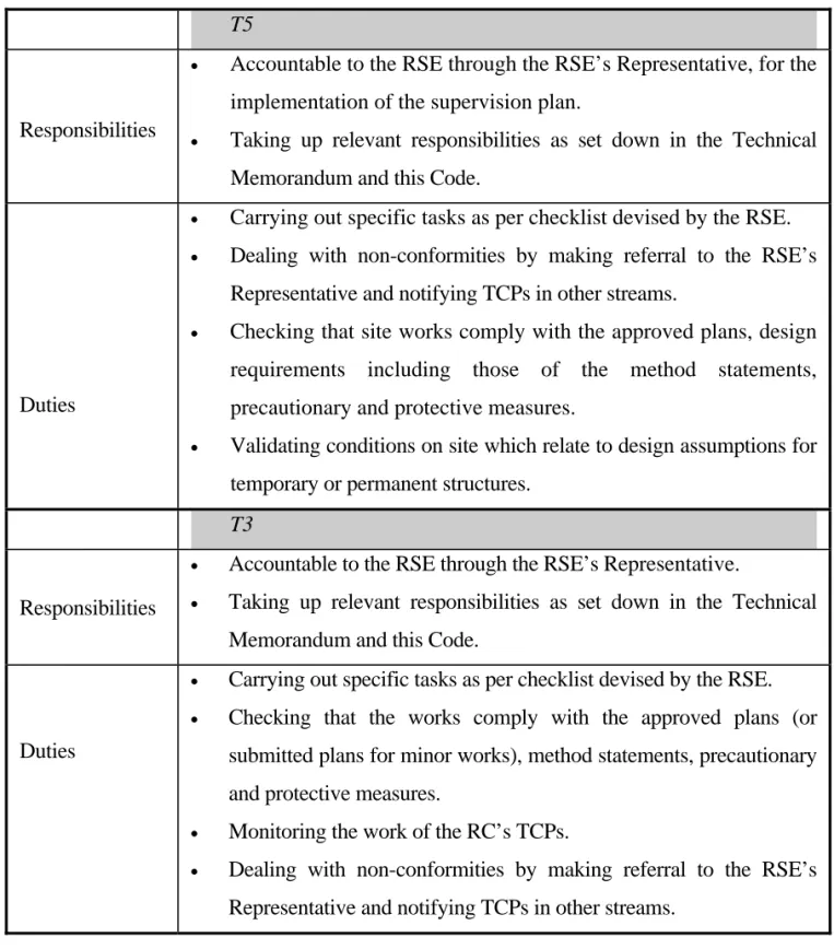
T5
Responsibilities
Accountable to the RSE through the RSE’s Representative, for the
implementation of the supervision plan.
Taking up relevant responsibilities as set down in the Technical
Memorandum and this Code.
Duties
Carrying out specific tasks as per checklist devised by the RSE.
Dealing with non-conformities by making referral to the RSE’s
Representative and notifying TCPs in other streams.
Checking that site works comply with the approved plans, design
requirements including those of the method statements, precautionary and protective measures.
Validating conditions on site which relate to design assumptions for
temporary or permanent structures. T3
Responsibilities
Accountable to the RSE through the RSE’s Representative.
Taking up relevant responsibilities as set down in the Technical
Memorandum and this Code.
Duties
Carrying out specific tasks as per checklist devised by the RSE.
Checking that the works comply with the approved plans (or
submitted plans for minor works), method statements, precautionary and protective measures.
Monitoring the work of the RC’s TCPs.
Dealing with non-conformities by making referral to the RSE’s
Table 4.3
Responsibilities and Duties under RGE’s Stream
Registered Geotechnical Engineer
Responsibilities
Assuming overall responsibilities in the appointment of his
Representative and TCPs.
Ensuring the full implementation of the supervision plan regarding
his own stream.
Overseeing the full implementation of the supervision plan
regarding the RC’s stream.
Giving permission to the RC for carrying out temporary works
categorized as Case 3 under paragraph 4.7 of this Code.
Duties
Compiling his own part of the supervision plan.
Devising checklists of specific tasks for his TCPs.
Supervising his Representative and TCPs.
Notifying the AP of any non-conformities which pose an imminent
danger, or cause a material concern for safety and the RC fails to rectify.
Carrying out site inspections as necessary.
RGE’s Representative
Accountable to the RGE for implementing the RGE’s supervision
plan.
Representing the RGE as the formal point of contact in
communication with other functional streams.
Taking overall responsibility to check if the safety measures on
site meet with the requirements of supervision plans.
Accountable to the RGE for the satisfactory execution of the
specific tasks, and for the responsibilities of junior TCPs including checking of the essential items for specific tasks provided in this Code.
Checking and satisfying that the RC’s safety management structure
complies with the supervision plan. Responsibilities
Duties
Assisting the RGE in carrying out safety management functions.
Coordinating and compiling reports on supervision activities
including reports on non-conformity.
Table 4.3 Cont’d
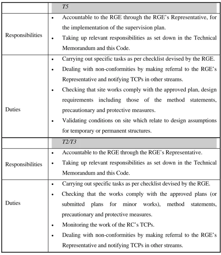
T5
Responsibilities
Accountable to the RGE through the RGE’s Representative, for
the implementation of the supervision plan.
Taking up relevant responsibilities as set down in the Technical
Memorandum and this Code.
Duties
Carrying out specific tasks as per checklist devised by the RGE.
Dealing with non-conformities by making referral to the RGE’s
Representative and notifying TCPs in other streams.
Checking that site works comply with the approved plan, design
requirements including those of the method statements, precautionary and protective measures.
Validating conditions on site which relate to design assumptions
for temporary or permanent structures. T2/T3
Responsibilities
Accountable to the RGE through the RGE’s Representative.
Taking up relevant responsibilities as set down in the Technical
Memorandum and this Code.
Duties
Carrying out specific tasks as per checklist devised by the RGE.
Checking that the works comply with the approved plans (or
submitted plans for minor works), method statements, precautionary and protective measures.
Monitoring the work of the RC’s TCPs.
Dealing with non-conformities by making referral to the RGE’s
Table 4.4
Responsibilities and Duties under RC’s Stream
Authorized Signatory
Responsibilities
Assuming overall responsibilities in the appointment of his
Representative and TCPs.
Ensuring the full implementation of the supervision plan regarding
his own stream.
Ensuring that non-conformities are immediately acted on and that
rectification is carried out forthwith.
Duties
Compiling his own part of the supervision plan.
Devising checklists of specific tasks for his TCPs.
Supervising his Representative and TCPs.
Preparing plans, method statement and/or precautionary and
protective measures for temporary works categorized as Case 2 and/or Case 3 under paragraph 4.7 of this Code.
Notifying the AP of any non-conformities which pose an imminent
danger, or cause a material concern for safety.
Carrying out site inspections as necessary.
AS’s Representative
Responsibilities
Accountable to the AS for the implementation of the RC’s
supervision plan.
Representing the AS as the formal point of contact in
communication with other functional streams.
Taking up overall responsibilities in carrying out site safety
measures and actions in accordance with the supervision plan.
Ensuring that the line management, including sub-contractors, are
conversant with the supervision plan, and that good coordination and communication exists between his TCPs.
Duties
Directing staff and sub-contractors on safety related matters.
Coordinating and compiling reports on supervision activities.
Dealing with non-conformities.
Assisting the AS in the investigation of the causes of each
Table 4.4 Cont’d
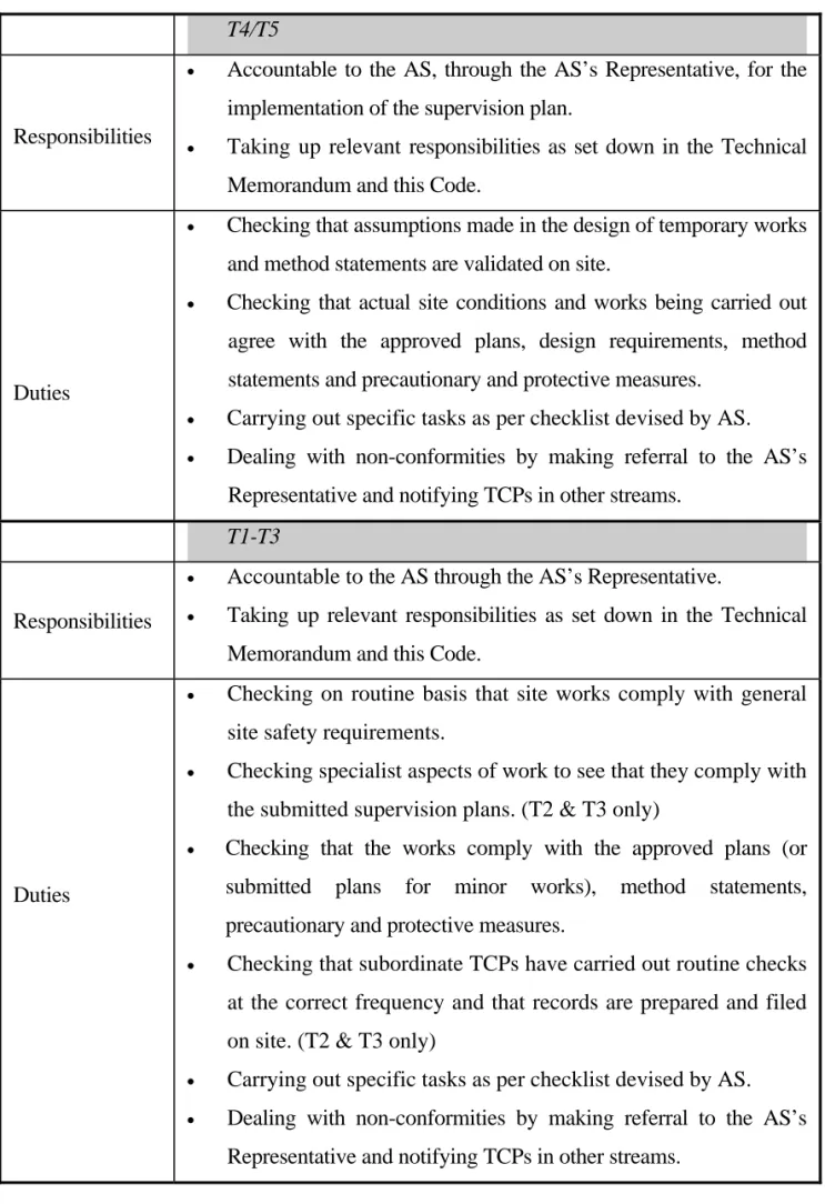
T4/T5
Responsibilities
Accountable to the AS, through the AS’s Representative, for the
implementation of the supervision plan.
Taking up relevant responsibilities as set down in the Technical
Memorandum and this Code.
Checking that assumptions made in the design of temporary works
and method statements are validated on site.
Checking that actual site conditions and works being carried out
agree with the approved plans, design requirements, method statements and precautionary and protective measures.
Carrying out specific tasks as per checklist devised by AS.
Dealing with non-conformities by making referral to the AS’s
Representative and notifying TCPs in other streams. Duties
T1-T3
Responsibilities
Accountable to the AS through the AS’s Representative.
Taking up relevant responsibilities as set down in the Technical
Memorandum and this Code.
Duties
Checking on routine basis that site works comply with general
site safety requirements.
Checking specialist aspects of work to see that they comply with
the submitted supervision plans. (T2 & T3 only)
Checking that the works comply with the approved plans (or
submitted plans for minor works), method statements, precautionary and protective measures.
Checking that subordinate TCPs have carried out routine checks
at the correct frequency and that records are prepared and filed on site. (T2 & T3 only)
Carrying out specific tasks as per checklist devised by AS.
Dealing with non-conformities by making referral to the AS’s
Division of responsibility between AP/RSE/RGE and RC for Temporary Works and Working Procedures
4.6 The AP/RSE/RGE/RC have the responsibility to ensure the integrity of
the temporary structure itself and the associated fixing methods.
4.7 The division of responsibility between AP/RSE/RGE and RC for
temporary works and working procedures is detailed below:
Case 1 When the prescribed plans stipulate the temporary works, and the sequence of construction or method statements are also shown on prescribed plans, both the AP/RSE/RGE and the RC have their own responsibilities to supervise the carrying out of the works in accordance with the approved/prescribed plans and the Buildings Ordinance and Regulations.
Case 2 When the temporary works, the sequence of construction or method statements are not required to be shown on prescribed plans and have no effect on the permanent structure by way of overstressing or overloading, the RC has the sole responsibility of ensuring the integrity of temporary works and that the carrying out of temporary works should be safe and should not endanger the workers on site, the public and adjoining buildings. Case 3 When the temporary works, the sequence of construction or
method statements are not required to be shown on the prescribed plans but may have effect on the permanent structure by way of overstressing or overloading, the RC shall appoint a person whose qualification and experience are not inferior to a TCP of grade T5 to certify the plans, design information and/or method statement of the temporary works which are to be submitted to the Project RSE/RGE. The person so appointed should also certify the completion of such works. The RSE/RGE may require the RC to submit further calculations to substantiate his design of the temporary works as necessary.
Figure 4.2 Flow Chart Showing Procedures for Dealing with Temporary Works
Will it cause any effect on the permanent structure?
Does the temporary works require BA’s
approval?
Case 3
Case 2 Case 1
Project RSE/RGE to give permission for the carrying out of such works.
The RC to submit the certified plans etc to
the Project RSE/RGE 21 days before commencement of such works. RC to prepare plans etc. and to appoint a person at T5
or equivalent level, to certify such plans etc.
RC to submit the completion certificate to the Project RSE/RGE within 14 days after completion of the works. The appointed person to certify completion of such works.
RC to carry out such works.
RC to prepare plans etc. and to
carry out and complete such
works. Upon approval and
consent by the BA, the RC to carry out and complete
such works. AP/RSE/RGE to prepare plans for BA's approval and to supervise works.
Yes
No No
Yes
START
4.8 For Case 2, method statements and drawings, precautionary and protective measures are required for, but not limited to, the following works :
(i) False work erected for the concrete casting of
(a) transfer plate and vehicular ramps (b) cantilevered slab exceeding 1.5m (c) beam with span exceeding 12m (d) deep beams with depth exceeding 3m (e) elevated water tank
(f) space frame
(g) vehicular bridge and footbridge
(h) prestressed structure
(ii) Formwork and shoring for the concrete casting of
(a) columns and walls with height exceeding 6m (b) retaining wall higher than 4m
(iii) Temporary working platforms for the operation of plant and machinery
(iv) Lifting operation of plant and machinery.
4.9 For all Cases 1, 2 and 3 above, the RC shall maintain on site a set of plans
showing the method statement and precautionary and protective measures for the reference of the TCPs and the inspection of the BA, which shall be listed out in a register on site.
Communication Procedures
4.10 Successful implementation of the Supervision Plan System requires effective and
efficient communication within and between each stream. Within streams, lines of communication should be established between the engineering safety supervision level and the routine safety supervision level whereas interstream communications should usually take place between stream counterparts. Typical lines of communication within stream and between streams are illustrated in Figure 4.1.
5 Typical Items for Specific Tasks by TCPs
5.1 The AP, RSE, RGE and AS shall devise check lists for their TCPs by making
reference to the typical items listed in Tables 5.1 to 5.4 of this Code and to include any other particular items considered appropriate and necessary for their projects and surrounding conditions.
5.2 The TCPs shall carry out their duties as per the check lists devised by their
own heads of stream and all the check lists and inspection records shall be kept on site for the inspection of the BA.
5.3 A typical checklist suggested for use, Form A, is shown in Appendix II to this
Code.
5.4 All non-conformities detected during the checking of typical items for specific
tasks by the TCPs must be properly recorded in the Non-Conformity and Rectification Reports, Form B at Appendix III to this Code. Detailed procedures for dealing with non-conformities are specified in paragraph 10.3 of this Code.
Table 5.1
Typical Items for the Check List of Specific Tasks for AP’s TCPs Item
No.
Description A1 Establish systems for co-ordinating, compiling and filing of reports, maintaining
filing systems; and forwarding reports to AP in case of non-conformity.
e
n s
ti m
u
ite
Ro
A2 Check that the hoarding and/or covered walkways are erected to secure safety of the public in accordance with the hoarding plan agreed by the BA.
A3 Check that the provision and condition of scaffolding, catch fans, matscreens and heavy duty nylon mats, as appropriate, are satisfactory.
A4 Check that monitoring check points are installed and readings are taken in time. A5 Register reports of non-conformity and inform relevant parties of non-conformity.
s
me
t
g i
ni
re
e
n
ngi
d E
na
e
ni
ut
o
R
A6 Report to the AP if the non-conformity is considered to pose an imminent danger, to be a significant risk or a source of danger or the RC does not comply with rectification instructions.
A7 Check that all lower grade TCPs and RC’s TCPs are making inspections no less than the required frequency and carrying out duties in accordance with the Technical Memorandum and the Code of Practice for Site Supervision.
A8 Check and satisfy that copies of approved plans (or submitted plans for minor works), method statements, precautionary and protective measures proposals and all related drawings are kept on site; and that they are followed, including checking the video record for demolition works.
A9 Check and monitor that lateral supports are installed in accordance with approved/agreed sequence and not to be removed in advance of adequate propping or restraint.
ng i
r s
ee m
ni
g ite
n
E
An Any other items considered essential by the AP for the project, including those
for quality supervision and other conditions imposed by the BA at approval and/or consent stage.
Table 5.2
Typical Items for the Check List of Specific Tasks for RSE’s TCPs Item
No.
Description
E1 Establish system for communicating with other TCPs.
Ro
u
ti
n
e
item
s
E2 Check that all monitoring check points are installed and readings are being taken in time.
E3 Verify non-conformity and instruct rectification works. Notify all relevant parties in respect of the non-conformity and monitor that rectification measures are properly carried out.
R
o
ut
in
e a
n
d
E
ngi
n
ee
ri
n
g
item
s
E4 Report to the RSE if the non-conformity is considered to pose an imminent danger, to be a significant risk or a source of danger or the RC does not comply with rectification instructions.
E5 Check that all lower grade TCPs and RC’s TCPs are making inspections no less than the required frequency and carrying out duties in accordance with the Technical Memorandum and the Code of Practice for Site Supervision.
E6 Check and satisfy that copies of approved plans (or submitted plans for minor works), method statements, precautionary and protective measures proposals and all related drawings are kept on site; and that they are followed, including checking the video record for demolition works.
E7 Check that there is no over-excavation and temporary cut slopes will not cause any instability to adjoining ground/structure/building.
ng i
r s
ee
ni
g item
n
E
E8 Check that enclosing walls for top down construction show no signs of defect or lack of soundness.
E9 Check and monitor that lateral supports are installed in accordance with approved/agreed sequence and not to be removed in advance of adequate propping or restraint.
E10 Check that the design and supports of formwork, shoring and temporary working platform are adequate to support all intended loads.
E11 Check that there is no risk of artesian conditions for excavation and lateral support works.
E12 Check that stability and integrity of nearby buildings and ground are not adversely affected.
E13 Check that the groundwater table is consistent with design of excavation and lateral support works.
E14 Check that before excavation takes place, the highest new deck level for top down construction is in place and has achieved sufficient strength to provide lateral support.
En Any other items considered essential by the RSE for the project, including
those for quality supervision and other conditions imposed by the BA at approval and/or consent stage.
Table 5.3
Typical Items for the Check List of Specific Tasks for RGE’s TCPs Item
No.
Description
G1 Establish system for communicating with other TCPs.
Ro
u
ti
n
e
item
s
G2 Check that all monitoring check points are installed and readings are being taken in time.
G3 Verify non-conformity and instruct rectification works immediately. Notify all relevant parties in respect of the non-conformity and monitor that rectification measures are properly carried out.
R
o
ut
in
e a
n
d
E
ngi
n
ee
ri
n
g
item
s
G4 Report to the RGE immediately if the non-conformity is considered to pose an imminent danger, to be a significant risk or a source of danger or the RC does not comply with rectification instructions.
G5 Check that all lower grade TCPs and RC’s TCPs are making inspections no less than the required frequency and carrying out duties in accordance with the Technical Memorandum and the Code of Practice for Site Supervision.
G6 Check and satisfy that copies of approved plans (or submitted plans for minor works), method statements, precautionary and protective measures proposals and all related drawings and geotechnical documentation are kept on site; and that they are followed, including checking the video record for demolition works.
G7 Check that there is no over-excavation/over-loading and temporary cut and fill slopes will not cause any inadequate margin of safety against instability to adjoining ground/buildings/structures/utility services or any harm to members of the public and workers on site.
G8 Check and monitor that the sequence of work and necessary protection works and supports are installed in accordance with approved plans/agreed method statements/precautionary measures proposals and that the supports are not to be removed or loaded in advance of adequate propping or restraint.
G9 Check that there is no risk of hydraulic failure causing ground collapse or
excessive deformation. g
ni
r s
e
nei
g item
n
E
G10 Check that there is adequate margin of safety against instability and integrity/functionality of nearby ground/buildings/structures/utility services and members of public and workers on site are not adversely affected/harmed.
G11 Check that the ground and groundwater conditions, ground deformations/vibrations and geotechnical hazards/risks are consistent with the design of excavation and lateral support works.
G12 Check that the geotechnical assumptions (i.e. ground model, surface water regime, ground water regime, ground deformations/vibrations, geotechnical hazards/risks, etc) are consistent with the geotechnical assessment/study/works design, and to assess their compatibility/adequacy taking into account the actual geotechnical conditions encountered on site and the original method statement and precautionary and protective measures proposed, and update the method statement, precautionary and protective measures and advise the RGE accordingly.
Gn Any other items considered essential by the RGE for the project, including
those for quality supervision and other conditions imposed by the BA at approval and/or consent stage.
Table 5.4
Typical Items for the Check List of Specific Tasks for RC’s TCPs Item
No.
Description C1 Establish system for communicating with other TCPs.
Ro
u
ti
n
e
item
s
C2 Check that the erection of hoarding, covered walkway and catch platform has been erected to secure safety of the public in accordance with the hoarding plan agreed by the BA.
C3 Check and ensure that there are arrangements for access and egress of vehicles which are satisfactory and do not endanger the public or other road users.
C4 Check that scaffolding is adequately secured to the building to prevent collapse; catch fans, catch platforms and protection screens are adequately installed so as to secure safety against falling objects.
C5 Check that restraining guy ropes and/or nets are provided before removal of external walls for demolition works.
C6 Check that there is no excessive debris on floor slabs and against external walls for demolition works.
C7 Check that refuse chute and refuse openings are properly located.
C8 Check and ensure that all monitoring check points and other geotechnical instrumentation have been installed and are regularly monitored; the results are kept on site; and that abnormal readings are reported to AP/RSE/RGE and the BA. C9 Check that all monitoring check points are installed and the readings are taken in
time.
C10 Check that loose materials, boulders, construction plants or temporary stockpiles of materials are not present at the crest or intermediate benches of slopes.
C11 Check that if excavation plant and piling rigs are operated on ground, the state of the ground is fit for use; and if the plants are operated on an elevated working platform, the platform is adequate to support the plant and all other imposed loads.
R
o
ut
in
e a
n
d
E
ngi
n
ee
ri
n
g
item
s
C12 Check and satisfy that copies of approved plans (or submitted plans for minor works), method statements, precautionary and protective measures proposals and all related drawings are kept on site; and that they are followed.
C13 Check that mechanical plant is operating safely and in accordance with method statements and proppings are provided in accordance with approved demolition plans.
Table 5.4 Cont’d
Item No.
Description
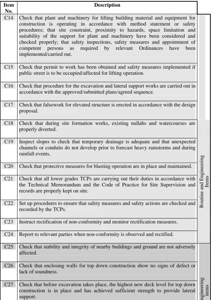
C14 Check that plant and machinery for lifting building material and equipment for construction is operating in accordance with method statement or safety procedures; that site constraint, proximity to hazards, space limitation and suitability of the support for plant and machinery have been considered and checked properly; that safety inspections, safety measures and appointment of competent persons as required by relevant Ordinances have been implemented/carried out.
R
o
ut
in
e a
n
d
E
ngi
n
ee
ri
n
g
It
em
s
C15 Check that permit to work has been obtained and safety measures implemented if public street is to be occupied/affected for lifting operation.
C16 Check that procedure for the excavation and lateral support works are carried out in accordance with the approved/submitted plans/agreed sequence.
C17 Check that falsework for elevated structure is erected in accordance with the design proposal.
C18 Check that during site formation works, existing nullahs and watercourses are properly diverted.
C19 Inspect slopes to check that temporary drainage is adequate and that unexpected channels or conduits do not develop prior to forecast heavy rainstorms and during rainfall events,
C20 Check that protective measures for blasting operation are in place and maintained. C21 Check that all lower grades TCPs are carrying out their duties in accordance with
the Technical Memorandum and the Code of Practice for Site Supervision and records are properly kept on site.
C22 Set up procedures to ensure that safety measures and safety actions are checked and recorded by the TCPs.
C23 Instruct rectification of non-conformity and monitor rectification measures. C24 Report to relevant parties when non-conformity is observed and rectified.
C25 Check that stability and integrity of nearby buildings and ground are not adversely affected.
E
n
g
ine
er
ing
item
s
C26 Check that enclosing walls for top down construction show no signs of defect or lack of soundness.
C27 Check that before excavation takes place, the highest new deck level for top down construction is in place and has achieved sufficient strength to provide lateral support.
C28 Check that during excavation for top down construction, there is no unexpected deflection on the highest deck level and subsequent new floor levels.
Table 5.4 Cont’d
Item No.
Description
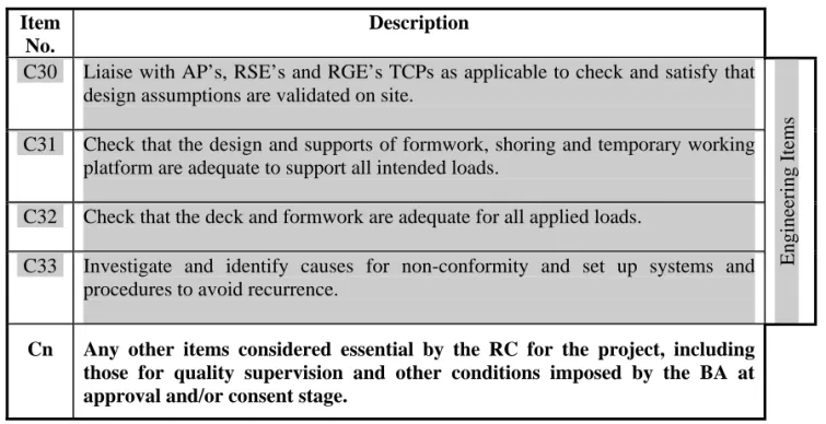
C30 Liaise with AP’s, RSE’s and RGE’s TCPs as applicable to check and satisfy that design assumptions are validated on site.
E
ngi
ne
er
in
g I
te
ms
C31 Check that the design and supports of formwork, shoring and temporary working platform are adequate to support all intended loads.
C32 Check that the deck and formwork are adequate for all applied loads.
C33 Investigate and identify causes for non-conformity and set up systems and procedures to avoid recurrence.
Cn Any other items considered essential by the RC for the project, including
those for quality supervision and other conditions imposed by the BA at approval and/or consent stage.
6 Quality Supervision Requirements
Scope of Quality Supervision
6.1 Quality supervision is applicable for ground investigation field works, soil
nailing works and foundation works.
Principles of Quality Supervision
6.2 For quality supervision, the principles described in paragraphs 6.3 to 6.6 below
will be followed.
6.3 In accordance with Building (Administration) Regulation (B(A)R) 37(1) and
(2), the RSE and RGE should each give such periodic supervision and make such inspections as may be necessary for building works. For such purpose, they should each have a team of TCPs to inspect the works at a specified frequency and supervise the carrying out of a specified percentage of the works. The RSE, RGE and their TCPs should all be respectively accountable under the BO for the quality of building works but in accordance with their respective responsibilities as specified.
6.4 As the RSE and/or RGE have overall responsibility for the works, they should
personally inspect and supervise the works at such frequency and extent as they consider appropriate in the circumstances of each case.
6.5 The RC, represented by their AS, should have a similar system of supervision
as that of the RSE and/or RGE above, but they should give continuous supervision in accordance with B(A)R 41(1). Even if some of the building works are carried out by their sub-contractors, it remains the responsibility of the RC to ensure that the building works and continuous supervision are properly done in accordance with the provisions of the BO and the system of supervision described above.
6.6 Inspection records should be kept for each member of the supervision team who should report any non-conformities to the RSE, RGE or AS, as the case may be.
Quality Supervision for Ground Investigation Field Works
6.7 All ground investigation field works, in both scheduled and non-scheduled areas,
should be carried out by a Registered Specialist Contractor (Ground Investigation Field Works category) (RSC(GIFW)) under proper supervision. To ensure quality of the works, supervision for the different stages of pre-design ground investigation field works, such as drilling/coring, sampling, instrumentation and field testing, should comply with the requirements set out in Table 6.1.
Table 6.1
Stages of Ground Investigation Field Works Item
No.
Stage Description
I1 Drilling/coring Check that drilling techniques/methods adopted are suitable
for the ground conditions encountered.
In Scheduled Areas, check that drilling techniques/methods comply with the approved plans.
I2 Sampling Check that the sampling techniques adopted are appropriate to
the quality of samples required and ground conditions encountered; ensure that the samples are properly extruded, sealed and stored and that they are not contaminated and their natural moisture content is maintained; and properly record the depths and locations at which the samples are recovered.
I3 Instrumentation Check that the field instruments are installed in accordance
with the standard of good practice or the manufacturer’s recommendations.
In Scheduled Areas, check that the field instruments are installed in accordance with the standard of good practice or the manufacturer’s recommendations, and in accordance with the approved plans.
I4 Field Testing Check that the tests are carried out in accordance with the
standard of good practice (excluding field density tests which are to be carried out by HOKLAS laboratories).
Note: Extent of works inspected should be shown in the checklist by each member of the supervision team.
6.8 All ground investigation field works should be carried out in accordance with the guidelines in GEOGUIDE 2 published by the Geotechnical Engineering Office. The drilling works should be carried out by experienced drillers under proper supervision.
6.9 Accurate and detailed borehole logs should be prepared to describe properly
the materials encountered so that checks of the logs can be made, and to allow comparison with materials revealed during construction. Logging of samples and preparation of borehole logs should be carried out by a competent person. All drillhole cores and samples obtained during ground investigation are to be kept in good conditions for testing or for the inspection by the BA, and if necessary Geotechnical Engineering Office, until acknowledgement of the satisfactory completion of the site formation, foundation or other related works has been given. The required qualifications of competent person for logging are defined in Appendix VII.
6.10 All ground investigation field works should comply with the administrative
procedures set out in Appendix VIII. A supervision plan should be submitted specifying the name of the TCPs appointed and the frequency of inspections and/or extent of supervision as required.
6.11 A ground investigation report submitted in support of a plan for approval
must contain a certificate by the RGE and RSC(GIFW) confirming the standards of ground investigation works (refer to details in item 6 of Appendix VIII).
6.12 The requirements specified above apply to ground investigation field works in
both scheduled and non-scheduled areas.
6.13 Foundation plans, site formation plans, excavation and lateral support plans and
general building plans accompanied by geotechnical assessment will be approved only when the BA is satisfied that the ground investigation field works have been undertaken by a RSC(GIFW) in compliance with the requirements specified and the results satisfy the design assumptions.
Quality Supervision for Soil Nailing Works
6.14 Quality supervision of soil nailing works should be provided by the RGE and his TCP T5 and T3, as well as by the AS of the RSC (Site Formation) and his TCP T4 and T1.
6.15 For all soil nailing works, at least one TCP T3 of the RGE and one TCP T1 of the RSC are required to be resident full-time on site during every stage of the works for each soil nail. The RSC is required to notify the RGE’s TCP T3 before the commencement of any stage of the works. The RSC is also required to prepare detailed inspection, measurement and testing records for each soil nail as per the approved plan requirements.
Table 6.2
Stages of Soil Nailing Works Item
No.
Stage Description N1 Pull-out test and any specified
site trial
Check whether the test nails are being constructed and the test/site trial procedure is in accordance with the approved plans or as specified by the RGE, and the acceptance criteria for the test/site trial are met.
N2 Setting out of soil nails Check whether the positions of the soil nails
agree with the approved plans.
N3 Drilling of soil nail holes Check whether the drillhole diameter,
length, inclination and bearing are in accordance with the approved plans and any anomalies on ground and groundwater conditions and to report to the responsible person if necessary.
Table 6.2 Cont’d
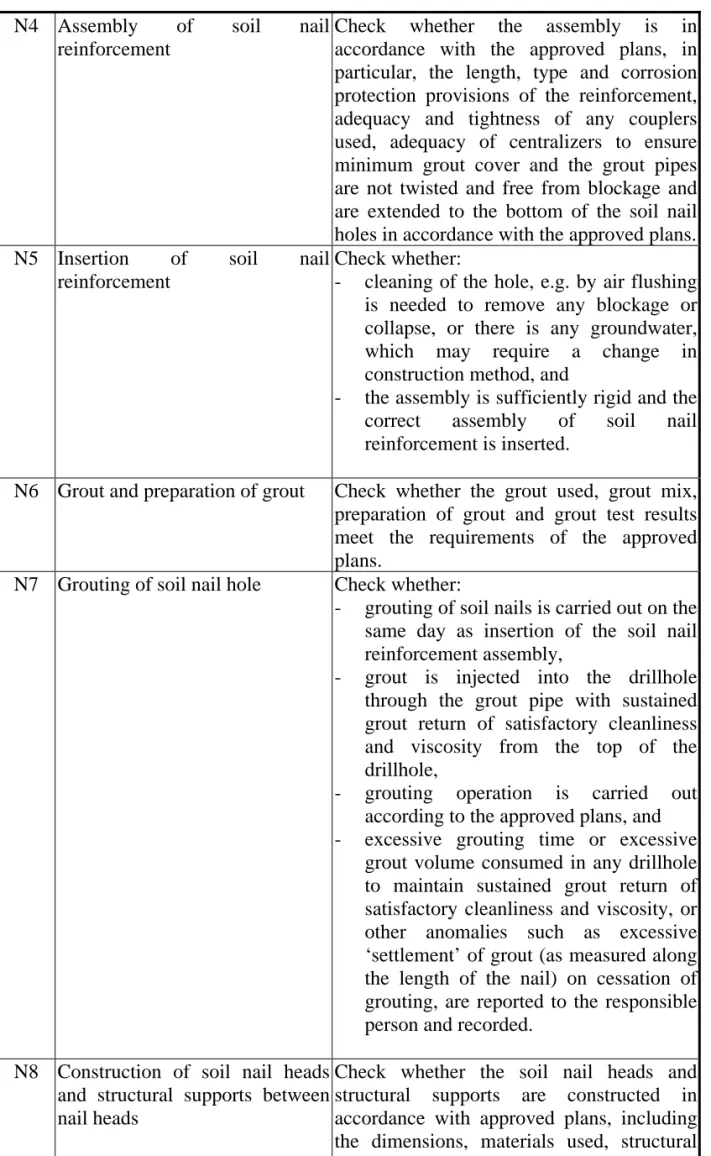
N4 Assembly of soil nail
reinforcement
Check whether the assembly is in accordance with the approved plans, in particular, the length, type and corrosion protection provisions of the reinforcement, adequacy and tightness of any couplers used, adequacy of centralizers to ensure minimum grout cover and the grout pipes are not twisted and free from blockage and are extended to the bottom of the soil nail holes in accordance with the approved plans.
N5 Insertion of soil nail
reinforcement
Check whether:
- cleaning of the hole, e.g. by air flushing
is needed to remove any blockage or collapse, or there is any groundwater,
which may require a change in
construction method, and
- the assembly is sufficiently rigid and the
correct assembly of soil nail reinforcement is inserted.
N6 Grout and preparation of grout Check whether the grout used, grout mix,
preparation of grout and grout test results meet the requirements of the approved plans.
N7 Grouting of soil nail hole Check whether:
- grouting of soil nails is carried out on the
same day as insertion of the soil nail reinforcement assembly,
- grout is injected into the drillhole
through the grout pipe with sustained grout return of satisfactory cleanliness and viscosity from the top of the drillhole,
- grouting operation is carried out
according to the approved plans, and
- excessive grouting time or excessive
grout volume consumed in any drillhole to maintain sustained grout return of satisfactory cleanliness and viscosity, or other anomalies such as excessive ‘settlement’ of grout (as measured along the length of the nail) on cessation of grouting, are reported to the responsible person and recorded.
N8 Construction of soil nail heads and structural supports between nail heads
Check whether the soil nail heads and structural supports are constructed in accordance with approved plans, including the dimensions, materials used, structural detailing and workmanship.
6.16 Key records on supervision of soil nailing works (Appendix IX) should also be prepared and certified by the RGE’s TCP T3 who carries out the inspection, measurement or check. A full set of all certified records should be kept on site for the inspection by the BA.
6.17 The RGE’s TCP T5 personnel should verify the design assumptions and carry
out design review during construction. He should check whether there are any anomalies that may invalidate the functional requirements of his design during his periodic site inspections and follow them up. He should also follow up any anomalies reported to him by the RGE’s TCP T3. If necessary, the RGE should make amendment submissions for the approval of the BA.
6.18 The extent of supervision required for different stages of soil nailing works is
shown in Table 6.2. Actual supervision requirements will be imposed at plan approval stage by the BA on a case-by-case basis depending on the scale and complexity of the slope and the soil nailing works, and the anticipated construction difficulties. The RGE should nominate to the BA, an adequate number of qualified supervision personnel with suitable experience, taking into account the site conditions and the number of soil nails proposed and their lengths. During the construction stage, the RGE should review the adequacy of the supervision team taking into account the likelihood of concurrent construction requiring close supervision under the construction programme.
6.19 The RGE’s TCP T5 should provide supervision as necessary during all stages
in Table 6.2. Moreover, he is required to provide the following supervision personally :
(a) pull-out test and any specified site test – at least 1 nail each of pull-out
test and site trial;
(b) insertion of soil nail reinforcement – at least 2 working nails at early
stage of nail construction;
(c) grouting of soil nail hole – at least 2 working nails at early stage of nail
(d) construction of soil nail heads and structural supports between nail heads – at least one soil nail head.
6.20 The RSC’s TCP T4 should also provide supervision as necessary during all
stages in Table 6.2. Moreover, he is required to provide the following supervision personally :
(a) pull-out test and any specified site test – at least 1 nail each of pull-out
test and site trial;
(b) insertion of soil nail reinforcement – at least 2 working nails at early
stage of nail construction;
(c) grouting of soil nail hole – at least 2 working nails at early stage of nail
construction; and
(d) construction of soil nail heads and structural supports between nail
heads – at least one soil nail head.
6.21 On completion of installation of soil nails, the RGE shall submit to the BA
key supervision records in the form of Appendix IX certified by his TCP T3. Upon review of the supervision records, if the BA considers that there is cause for concern in relation to the quality of soil nailing works, the BA will require the RGE to carry out non-destructive testing (NDT) of at least 1% of soil nails with a minimum of 2 nails per slope (including wall) to verify the length of the installed soil nails.
6.22 Several NDT methods for checking the length of installed soil nails are
described in GEO Report No. 133 “Non-destructive Tests for Determining the Lengths of Installed Steel Soil Nails”. Alternatively, the RGE may propose other methods for BA’s agreement at the design stage of the project. A test report with the test results and their interpretations together with re-assessment of the adequacy of the installed soil nails (if needed) shall be submitted to the BA for acceptance.
Quality Supervision for Foundation Works
6.23 Quality supervision of foundation works should be provided by the RSE and
his TCP T5 and T3, as well as by the AS of the RSC and his TCP T4 and T2. Depending on the nature of the various stages of foundation works, TCPs should either be full-time on site or inspect certain percentage of the works as specified in this Code.
6.24 The stages of the various types of foundation works are shown in Table 6.3.
Actual supervision requirements will be imposed by the BA at plan approval and consent stage on a case-by-case basis depending on the scale and extent of the foundation works.
Table 6.3
Stages of Various Types of Foundation Works Item
No.
Stage Description
F1
(a) Driven Piles
(i) Setting out of piles Check that the locations of piles agree with
approved plans.
F2 (ii) Driving test Check that design assumptions agree with actual
site conditions during driving tests.
F3 (iii) Driving of piles Check that the accepted working procedures of
pile driving are followed and anomalies rectified during pile driving.
F4 (iv) Splicing of piles Check the accuracy of design details during pile
splicing.
F5 (v) Final sets Check that the required final set has been
achieved and the capacity of each pile complied with approved plans.
F6 (vi) Proof test
(Verification on the performance of the as-constructed piles by the imposition of test load)
Check that the testing procedures and acceptance criteria of proof tests are in accordance with PNAP APP-18 (previously PNAP 66) and measurements are properly recorded during the test.
Table 6.3 Cont’d
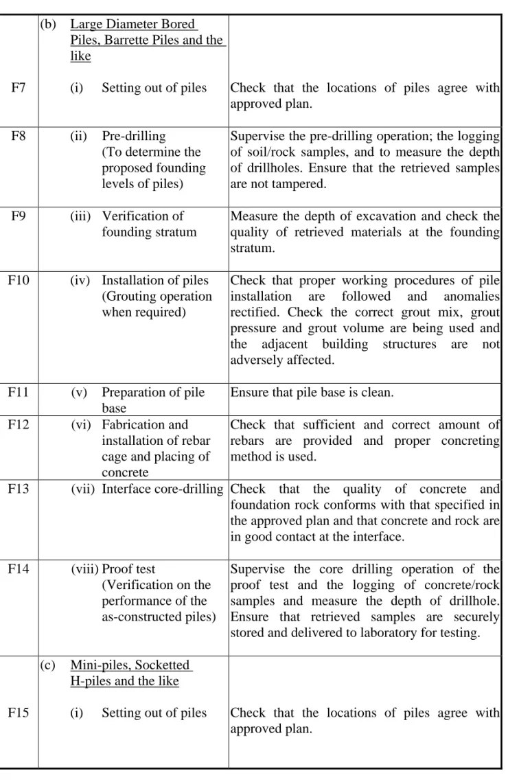
F7
(b) Large Diameter Bored
Piles, Barrette Piles and the like
(i) Setting out of piles
Check that the locations of piles agree with approved plan.
F8 (ii) Pre-drilling
(To determine the proposed founding levels of piles)
Supervise the pre-drilling operation; the logging of soil/rock samples, and to measure the depth of drillholes. Ensure that the retrieved samples are not tampered.
F9 (iii) Verification of
founding stratum
Measure the depth of excavation and check the quality of retrieved materials at the founding stratum.
F10 (iv) Installation of piles
(Grouting operation when required)
Check that proper working procedures of pile installation are followed and anomalies rectified. Check the correct grout mix, grout pressure and grout volume are being used and the adjacent building structures are not adversely affected.
F11 (v) Preparation of pile
base
Ensure that pile base is clean.
F12 (vi) Fabrication and
installation of rebar cage and placing of concrete
Check that sufficient and correct amount of rebars are provided and proper concreting method is used.
F13 (vii) Interface core-drilling Check that the quality of concrete and
foundation rock conforms with that specified in the approved plan and that concrete and rock are in good contact at the interface.
F14 (viii)Proof test
(Verification on the performance of the as-constructed piles)
Supervise the core drilling operation of the proof test and the logging of concrete/rock samples and measure the depth of drillhole. Ensure that retrieved samples are securely stored and delivered to laboratory for testing.
F15
(c) Mini-piles, Socketted
H-piles and the like
(i) Setting out of piles Check that the locations of piles agree with
Table 6.3 Cont’d
F16 (ii) Pre-drilling
(To determine the proposed founding levels of piles)
Supervise the pre-drilling operation; the logging of soil/rock samples, and to measure the depth of drillholes. Ensure that the retrieved samples are not tampered.
F17 (iii) Verification of
founding stratum
Measure the depth of excavation and check the quality of retrieved materials at the founding stratum.
F18 (iv) Installation of piles
(Grouting operation when required)
Check that proper working procedures of pile installation are followed and anomalies rectified. Check the correct grout mix, grout pressure and grout volume are being used and the adjacent building structures are not adversely affected.
F19 (v) Installation of rebar
and grouting
Check that sufficient and correct amount of rebars are provided and proper grouting method is used.
F20 (vi) Proof test
(Verification on the performance of the as-constructed piles by the imposition of test load)
Check that the testing procedure and acceptance criteria of the proof tests are in accordance with PNAP APP-18 (previously PNAP 66) and measurements are properly recorded during the test.
F21 (vii) Post-installation
borehole drilling
Verify the rockhead profile and socket length of piles during post-installation borehole drilling.
F22
(d) Rafts and Spread Footings
(i) Setting out of rafts
and spread footings
Check that the locations and sizes of rafts and spread footings agree with approved plan (or the submitted plans for minor works).
F23 (ii) Inspection of bearing
stratum
Check the compliance of ground bearing stratum with approved plans (or the submitted plans for minor works), site investigation reports and design assumptions.
F24 (iii) Fixing of rebars and
checking of concrete covers
Check that sufficient amount of rebars and good workmanship are provided.
F25 (iv) Placing, compaction
and curing of concrete
Ensure the quality and workmanship of concrete works.
F26 (v) Plate loading test
(where required) l
(To verify the adequacy of ground bearing stratum)
Check that the accepted testing procedures of plate oading test are followed and measurements are correctly recorded.
Note : Foundation unit inspected should be shown in the checklist by each member of the supervision team.
6.25 The AP, RSE and RSC should jointly submit a supervision plan, specifying the name of the TCPs appointed and frequency of inspection and/or extent of supervision, and carry out inspections and supervisions in accordance with the plan. The plan should be submitted prior to or at the same time as consent application for the foundation works. However, no prior approval of the TCPs is required before commencement of the foundation works. The AP/RSE/RSC are responsible to ensure that their TCPs satisfy the qualification and experience requirements specified and should notify the BA of any subsequent changes of TCPs. The plan should be kept on site for the inspection of the BA when required.
6.26 The RSE should provide supervision as necessary during all stages in Table
6.3.
6.27 The AS of the RSC should provide supervision as necessary during all stages
in Table 6.3.
6.28 Pre-drilling, interface core-drilling, post-installation drilling and proof test
core-drilling for foundation works must be carried out by a Registered Specialist Contractor in the Ground Investigation Field Works category and be supervised by the site supervisors responsible for the quality supervision of foundation works. There is no need to submit a separate supervision plan for the pre-drilling and post-installation drilling works.
7 Building Works with Significant Geotechnical Content
7.1 Building works with significant geotechnical content include the following
types of geotechnical works:
(a) site formation
blasting
prestressed ground anchors
prestressed ground anchors in sensitive sites* (see para 7.3)
soil nails
fill slopes (compaction and installation of such surface filter/drainage layers) greater than 5 m high, or less than 5 m high which pose a direct risk to life, i.e. Consequence-to-life Category 1 or 2 in PNAP APP-109 (previously PNAP 234)
reinforced fill slopes
(b) excavation and lateral support, and temporary retaining structures
depth > 4.5 m (depth > 7.5 m in sensitive sites* - see para 7.3)
(c) permanent retaining structures
diaphragm walls and bored-pile walls
reinforced fill structures
cantilever / gravity retaining walls (height > 5 m) and
screen/basement walls (height > 7.5m)
(d) ground treatment
vertical drains, horizontal/raking drains
grouting and dewatering for cut and cover excavation and
tunnel/shaft/cavern construction
ground water drainage works in Scheduled Area No. 1
(e) demolition works affecting slopes and retaining walls
ground stabilization works using soil nails or anchors
(f) foundation
foundation for buildings in Scheduled Area No. 1
deep foundation for buildings in Scheduled Areas Nos. 2 & 4 and
in Designated Area of Northshore Lantau
foundation that could affect an existing tunnel/cavern or that could
be affected by tunnel works
(g) water wells
well yield test and the effect of proposed water extraction.
(h) tunnel works* (tunnels/caverns/shafts/associated underground
facilities - see para 7.3)
cut and cover construction methods
drill and blast methods
tunnel boring machine, micro-tunnelling (including directional drilling) and pipe jacking methods
associated ground support, ground treatment and groundwater
control works
7.2 The list above is not intended to be exhaustive as it only contains the common
types of geotechnical works encountered.
7.3 In normal circumstances, a TCP T3 and a TCP T5 are required to be provided
by the RGE to supervise building works with significant geotechnical content. However, a Directorate Site Supervisor (DSS) may be required for geotechnically difficult or sensitive sites marked * in the above list or any other sites as considered appropriate by GEO and BD.
7.4 Sensitive sites are sites where the works could pose adverse impact to life
and/or property. These include sites where works could affect old buildings with shallow foundations, old tunnels/caverns, major roads, railways, water mains, gas mains, slopes, retaining walls or sites with history of instability.
7.5 The requirements for the provision of a DSS, if considered necessary by GEO
and BD, will be conveyed to the AP/RSE/RGE in the approval and consent letters. The name of the DSS should also be given in the supervision plan.
7.6 A DSS should be a Registered Professional Engineer in geotechnical
discipline who holds the position of a partner/director in the firm which prepared the geotechnical content of the submission. The RGE who is responsible for the project can also be accepted as the DSS.
8 Supervision Requirements
Determining the required TCPs and their frequency level of site inspections
8.1 The grades of TCP and their minimum frequency level of site inspections
required for each functional stream for various types of building works or street works are set out in Table 1 of the Technical Memorandum. More frequent supervision requirements during critical stages are specified in paragraph 9 of this Code.
8.2 For building works with significant geotechnical content, the RSE would only
be required to provide a team of site supervisors where there was structural works.
8.3 For foundation works in Scheduled Areas Nos. 1, 2 and 4 and in Designated
Area of Northshore Lantau, additional supervision from the RGE’s stream is required on top of the supervision requirements for foundation works given in Table 1 of the Technical Memorandum. Note 5 to Table 1 of the Technical Memorandum refers.
Scale of the Works
8.4 The effect of the scale of the works should be considered in determination of
supervision requirements. It shall be assessed by a scale factor of the works.
8.5 A measurable item and a basic value of which are assigned for each type of
building works or street works. The scale factor of a type of works is the ratio of the estimated value of the measurable item of the works to the basic value. The scale factor is capped at 2.
8.6 The measurable items and their basic values to be used for the assessment of
the scale factor of various types of building works or street works are set out in Table 8.1. Unless otherwise specified, the measurable items represent the total cost, average cost per month, or quantity of the respective type of building works or street works to be carried out. The BA may review and amend the measurable items and their basic values from time to time.