Sonoline A/B Pocket Fetal Doppler
CONTEC Medical Systems CO., LTD
www.drkits.com
Attention
This user manual is written and compiled in accordance with the council directive MDD93/42/EEC for medical devices and harmonized standards. In case of modifications and software upgrades, the information contained in this document is subject to change without notice.
The manufacturer makes no warranty of any kind with regard to this material, including, but not limited to the implied warranties of merchantability and fitness for a particular purpose. The manufacturer assumes no responsibility for any errors that may appear in this document, or for incidental or consequential damage in connection with the furnishing, performance or use of this material. No part of this document may be photocopied, reproduced or translated to another language without prior written consent of the manufacturer.
The information contained in this document is subject to change without notice. Responsibility of the Manufacturer
The manufacturer only considers itself responsible for any effects on safety, reliability and performance of the equipment if:
Assembly operations, repairs are carried out by persons authorized by the manufacturer, and the device is used in accordance with the instructions for use.
WARNING :
This device is not intended for treatment. The intended use is for detecting Fetal Heart Rate. If the FHR result is distrustful, please use other methods such as stethoscope to verify immediately.
Warranty
The unit can not be repaired by users themselves. All services must be done by the engineers approved by manufacturer. We warrant that each product we sell you is free from defects in labor and materials and shall conform to its product specifications as defined in the user documentation. If the product doesn't function as warranted during the warranty period, we will repair or replace it without charge. Misuse, improper maintenance may void the warranty.
Using This Label Guide
This guide is designed to give key concepts on safety precautions. WARNING :
A WARNING label advises against certain actions or situations that could result in personal injury or death.
CAUTION :
A CAUTION label advises against actions or situations that could damage equipment, produce inaccurate data, or invalidate a procedure.
Table of Contents
Chapter 1 Safety Guidance ... 1
1.1 Safety Precautions ... 1
Chapter 2 Introduction ... 4
2.1 Overview ... 4
2.2 Features ... 4
Chapter 3 Outlook and Configuration ... 5
3.1 Front Panel ... 6
3.2 Push Button ... 8
3.3 Introduction to Top Panel... 9
Chapter 4 General Operation ... 11
4.1 FHR Inspection ... 11
4.2 Mode Selection ... 11
4.3 Probe Operation ... 12
4.4 Inspection of Low Power ... 13
4.5 Replacing Battery ... 13
Chapter 5 Product Specification... 15
Chapter 6 Maintenance ... 17
6.1 Maintenance ... 17
6.2 Cleaning ... 17
6.3 Disinfecting and Sterilization ... 17
Chapter7 Solutions for Possible Problems ... 19
Appendix 1 ... 20
Appendix 2 ... 21
Chapter 1 Safety Guidance
This unit is internally powered equipment; the degree of shock protection is type B applied part.
Type B applied part protection means that these patient connections will comply with permitted leakage currents, dielectric strengths of IEC 60601-1.
1.1 Safety Precautions
WARNING and CAUTION messages must be observed. To avoid the possibility of injury, observe the following precautions during the operation of the device.
WARNING : This device is not explosion-proof and cannot be used in the presence of flammable anaesthetics.
WARNING : Do not throw batteries in fire as this may cause them to explode.
WARNING : Do not attempt to recharge normal dry-cell batteries, they may leak, and may cause a fire or even explode.
WARNING : Don’t touch signal input or output connector and the patient simultaneously.
WARNING : Accessory equipment connected to the analog and digital interfaces must be certified according to the respective IEC standards (e.g. IEC 950 for data processing equipment and IEC60601-1 for medical equipment). Furthermore all configurations shall comply with the valid version of the system standard IEC60601-1-1. Everybody who connects additional equipment to the signal input connector or signal output connector configures a medical system, and is therefore responsible that the system complies with the requirements of the valid version of the system standard IEC 60601-1-1. If in doubt, consult our technical service department or your local distributor.
WARNING : Sonoline Pocket Fetal Doppler is a tool to aid the healthcare professional and should not be used in place of normal fetal monitoring. This is not intended for fetal use.
WARNING : Replacing battery shall only be done outside the patient environment (1.5m away from the patient).
WARNING : Please use the Sonoline probe provided by the manufacturer.
WARNING : Do not pull the line of probe longer than 2 meters, or else the probe may break away from the connector of the Sonoline.
CAUTION : The device must be serviced only by authorized and qualified personnel.
CAUTION :The device is designed for continuous operation and is ‘ordinary’. Do not immerse in any liquid (i.e. not drip or splash- proof).
CAUTION : Keep the device clean. Avoid vibration.
CAUTION : Do not use high temperature sterilizing process and E-beam or gamma radiation sterilization.
CAUTION : Electromagnetic Interference-Ensure that the environment in which the device is operated is not subject to any sources of strong electromagnetic interference, such as radio transmitters,
mobile telephones, etc. Keep them far away.
CAUTION : The user must check that the equipment does not have visible evidence of damage that may affect patient safety or monitoring capability before use. The recommended inspection interval is once per month or less. If damage is evident, replacement is recommended before use.
CAUTION : The following safety checks should be performed once every two years or as specified in the institution’s test and inspection protocol by a qualified person who has adequate training,
knowledge, and practical experience to perform these tests. Inspect the equipment for mechanical and functional damage. Inspect the safety relevant labels for legibility.
Verify that the device functions properly as described in the instructions for use. Test the patient leakage current according to IEC 60601-1/1988: Limit: 100 uA (B).
The leakage current should never exceed the limit. The data should be recorded in an equipment log. If the device is not functioning properly or fails any of the above tests, the device has to be repaired.
CAUTION : The battery must be properly disposed according to local regulation after their use. CAUTION : The battery must be taken out from the battery compartment if the device will not be used for a long time.
CAUTION : The device shall only be used if the battery cover is closed. CAUTION : Battery must be stored in cool and dry place.
CAUTION : If use rechargeable battery, to insure capability and life, please fully charge batteries before first use, normally, batteries must be continuously charged over 14 hours or charged according to the guidance displayed on the battery.
CAUTION : Please don’t set anode and cathode of the battery wrongly. CAUTION : The valid period of this product is five years.
CAUTION : After the service life, please return the products to the manufacture or disposal the products according to local regulations.
CAUTION : This device cannot be used with defibrillator or high frequency surgical unit. CAUTION : Please choose the accessories authorized by our company or the device may be damaged.
CAUTION : Please keep the probe from edge tool.
CAUTION : Please use Sonoline under the environment without strong electromagnetic field, which may influence measure result.
When cleaning the machine:
CAUTION : Don’t use strong solvent, for example, acetone.
CAUTION : Avoid pouring liquids on the device while cleaning.
CAUTION : Don’t remain any cleaning solution on the surface of the device. When disinfecting the machine:
WARNING : Never try to sterilize the probe or equipment by low temperature steam or other methods.
Chapter 2 Introduction
2.1 Overview
Pocket Fetal Doppler is a hand-held obstetrical unit, which can be used in hospital, clinic and home for daily self-check by pregnant woman.
There are two different models available: Sonoline A and Sonoline B. Sonoline A model is for simple auscultation.
Sonoline B model is a high performance model with (fetal heart rate) LCD digital display. It has 3 work modes: real-time FHR display mode, averaged FHR display mode, and manual mode.
They are all availabe for user replaceable batteries. The user interface includes power button, mode button, volume control, single speaker, headphone jack and LCD display for heart rate, battery and working mode, probe type.
Both of the two models have audio output, and can be connected with earphone or recorder with audio input. They use standard 1.5 V DC alkaline battery (2 pieces). Rechargeable battery and charger can be optionally configured.
Sonoline A and Sonoline B includes four interchangeable probes (2MHz normal ultrasound probe, 2MHz water proof probe,3MHz normal ultrasound probe,3MHz water proof probe).
2.2 Features
Battery LED indicator (Sonoline A only) Battery status indicator (Sonoline B only) Low power inspection of the battery Built-in speaker
Output for headphones
2 MHz/3 MHz probe can be connected Probe inspection
Backlight (Sonoline B only) Auto shut off (Sonoline B only)
Chapter 3 Outlook and Configuration
Fig.3-1 Front Panel (Sonoline B as Example)
Fig.3-2 Rear Panel
Fig.3-3 Top Panel
Battery Compartment
Headphone
Attention Headphone Socket Probe
Backlight Control Button LCD Panel
Mode Button
Power Button
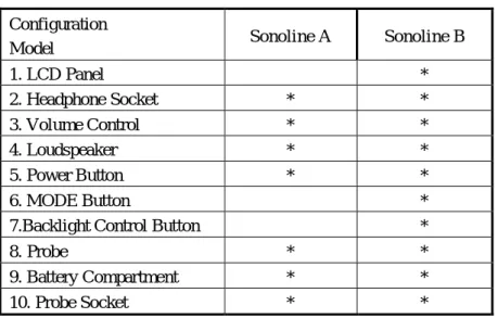
Table 1: Model and Config uration Configuration
Model Sonoline A Sonoline B
1. LCD Panel * 2. Headphone Socket * * 3. Volume Control * * 4. Loudspeaker * * 5. Power Button * * 6. MODE Button *
7.Backlight Control Button *
8. Probe * *
9. Battery Compartment * *
10.Probe Socket * *
* Indicated the model has the configuration.
3.1 Front Panel
3.1.1 Display
Sonoline A model: Indicator light will be green when turn on the machine. When the power of the battery is low, the LED indicator light of the battery will flicker in green color. When the probe falls away from the Sonoline A, the power indicator light turns into yellow and flicker.
While self-testing,the LCD display for Sonoline B is as follows:
Fig.3-4 LCD Display 3.1.2 Probe
Sonoline A and Sonoline B includes four interchangeable probes (2MHz normal ultrasound probe,2MHz water proof probe,3MHz normal ultrasound probe,3MHz water proof probe). 2MHz NormalUltrasound Probe:
The 2MHz normal ultrasound probe is standard configuration for the pocket fetal doppler.
Working Mode
FHR Display
Type of Probe
Fig.3-5 2MHz NormalUltrasound Probe The meanings of CD2.0 on the label are as follows:
C: The work mode for the probe is continuous wave. D: The structure form for the probe is cell type. 2.0: The frequency of the probe is 2 MHz.
3MHz Normal Ultrasound Probe:
The 3MHz normal ultrasound probe is optional configuration for the pocket fetal doppler.
Fig.3-6 3MHz Normal Ultrasound Probe The meanings of CD3.0 on the label are as follows:
C: The work mode for the probe is continuous wave. D: The structure form for the probe is cell type. 3.0: The frequency of the probe is 3 MHz.
Serious Statement:
The above are descriptions of 2MHz and 3MHz normal ultrasound probe, they are applicable for USA market and European market.
3.1.3 Probe Socket
Fig.3-7 Probe Socket
The probe socket is shown as Fig.3-7 above. The definition of the jacks of the socket is as below:
Pin Definition 1 Power Supply 2 Signal 3 Probe Coding 1 4 Probe Coding 2 5 Probe Coding 3 6 (Shell) GND
WARNING : Do not attempt to connect the probes which are not manufactured by our company with the machine.
3.2 Push Button
There are three push buttons POWER, MODE, and BACKLIGHT CONTROL and a volume control button on Pocket Fetal Doppler. The primary functions are as follows:
3.2.1 Power Button
Function: Power on/off
Power on: Push the button once
Power off: Push down the button until the machine is off (Sonoline A). Push down the button and hold 3 seconds to power off (Sonoline B)
For the Fetal Doppler has memory function, when turning on the machine, it will enter the mode selected before last power off automatically after self-testing.
3.2.3 Backlight Control Button (Sonoline B Only)
Function: Under mode 1 and mode 2, press the button to turn on /off backlight.
Under mode 3, the button is for start/stop operation, please refer to 4.2.3 manual mode (Mode 3)
3.2.4 Volume Control Indicator
Volume adjusting direction indicator.
From left to right means that the sound level is from high to low.
3.3 Introduction to Top Panel
Headphone Socket: a socket for audio output, and can be connected with earphone or recorder with audio input to record.
: The socket, terminal post, or switch that connected with the headphones. : Attention. Refer to the accompanying documents.
Accessory equipment connected to the analog and digital interfaces must be certified according to the respective IEC standards (e.g. IEC 950 for data processing equipment and IEC 60601-1 for medical equipment). Furthermore all configurations shall comply with the valid version of the system standard IEC60601-1-1. Everybody who connects additional equipment to the signal input connector or signal output connector configures a medical system, and is therefore responsible that the system complies with the requirements of the valid version of the system standard IEC60601-1-1. If in doubt, consult our technical service department or your local distributor.
3.3.1 Signal Interface
Headphone socket showed as Fig.3-8, the definition of pins showed as below: Pin Definition 1 GND 2 Signal 3 Signal 4 Signal 5 Signal
Chapter 4 General Operation
4.1 FHR Inspection
Power on by pressing the power button.
For Sonoline A, indicator light will be on in green color.
For Sonoline B, it will do self-test when turning on the machine. After self-testing, the LCD display is as Fig.3-4.
Find the position of fetus.
At first, please feel the position of the fetus by hand. Find out the best direction for inspecting the fetal heart. Apply a liberal amount of gel to the faceplate of probe; place the faceplate of probe at the best position for detecting fetal heart. Adjust the probe to obtain an optimum audio signal ideally by angling the probe around. Adjust the volume according to requirements.
FHR Calculation:
For Sonoline A, the method is to count the fetal heart beat times in one minute to get the FHR. For Sonoline B, the FHR result will be showed on LCD screen.
Turn off the machine
For Sonoline A, press power button to turn off the machine directly For Sonoline B, keep pressing the power button 3 seconds to turn off.
CAUTION :
Put the probe on the best detecting position to get better detecting effect.
Don't put the probe on the position where have strong Placental Blood Sound(PBS) or strong Umbilical Sound(UMS).
If pregnant woman adopts horizontal position and the fetus position is normal, put the probe on the position of lower navel midline to get the clearest FHR sound.
Do not measure FHR unless audible fetal sound has been heard.
4.2 Mode Selection
4.2.1 Real-time FHR Display Mode (Mode 1) This mode is only for Sonoline B.
At the moment of detecting FHR signal, the LCD will display the flashing heart symbol, and display real-time FHR simultaneously.
It is used to obtain more stable heart rate readings. In this mode, FHR is averaged 8 beats. The LCD displays the flashing heart symbol when displaying FHR.
4.2.3 Manual Mode (Mode 3) This mode is only for Sonoline B.
When entering into mode 3, the system will automatically counts the audible beats, FHR will be showed in “— — —” Format, and the LCD flashes heart symbol. Press the backlight control button to stop calculating. The unit will automatically calculate the derived FHR averaged over the caculating time and display the result. If measure FHR again, press the backlight control button to start. Repress it, it will stop calculating .This rate value is retained until the measurement is repeated or the mode is changed.
4.3 Probe Operation
4.3.1 Inspecting Probe
When the probe falls away from the Sonoline, for Sonoline A, the power indicator light turns into yellow and flicker. For Sonoline B, the LCD screen displays the flickering “— — —” and the probe frequency indication data disappeared. At this moment the probe needs to be reconnected. After connected well, LCD screen will stop flickering and display the probe frequency data.
4.3.2 Replacing Probe
There has been a probe connected to Sonoline while packaged by the manufacturer. If users need to replace it with another probe, power off the Sonoline at first, then take out the probe from the parking of Sonoline. And then pull out the plug of the probe from its socket. Then connect the plug of the probe which needs to be displaced with the socket.
Note: Place the temporarily unused probe carefully and avoid falling off, stress, etc. When the Sonoline is not used for a long time, users are recommended to connect the plug of one probe to Sonoline socket and put the probe in the parking. Then pack the Sonoline with the probe in the wrapping box.
4.3.3 Taking out Probe and Placing Probe Taking out the probe
Hold the main unit with one hand, and hold the handle of the probe with another hand to take out the probe. (See Fig.4-1).
Fig.4-1 Taking Out Probe Placing probe
It is opposite to take out probe. Hold the main unit with one hand, and hold the top of the probe with another hand, then push the probe into the probe holder.
4.4 Inspection of Low Power
For Sonoline A, when it works normally, the LED indicator light of the battery is green; but when the power of the battery is low to the degree that it cannot support the Sonoline A to work normally, the LED indicator light of the battery will flicker in green to remind the customer to change another new battery or charge the battery (only the chargeable battery can be charged.)
For Sonoline B, when it works normally,the LCD screen displays the status of the battery, and the number of the grid in the status represents how much power is left; when the power of the battery is low, the power of the battery displays grid 0 to remind the customer to change another new battery or charge the battery (only the chargeable battery can be charged.).
4.5 Replacing Battery
4.5.1 Taking out Battery
The rear panel is upturned. First open the battery compartment, then take out the battery from the battery compartment (see Fig.4-2).
Fig.4-2 Replacing Battery
4.5.2 Replacing Battery
First put two AA size batteries into the battery compartment (as for the direction of battery, please refer to the instruction inside the battery compartment), at last close the battery compartment.
CAUTION : The battery must be taken out from the battery compartment if the device will not be used for a long time.
Chapter 5 Product Specification
Product Name: Sonoline Pocket Fetal Doppler Model No.: Sonoline A and Sonoline B
Safety: Complies with: IEC 60601-1:1988 A1:1991 A2:1995 Classification:
Anti-electroshock Type: Internally powered equipment. Anti-electroshock Degree: Type B applied part
Harmful Liquid Proof Degree:
Main unit: Ordinary equipment (sealed equipment without liquid proof). Probe: Prevent from water splashing, degree of protection: IPX4.
Degree of Safety in Presence of Flammable Gases: Equipment not suitable for use in presence of flammable gases
Working System: Continuous running equipment EMC: Group I Class B
Suitable Using Range: Suitable for use after the 12th week of pregnancy Physical Characteristic
Size: 135 mm (Length) ×95 mm (Width) ×35 mm (Height) Weight: About 180 g (including batteries)
Environment Working:
Temperature: +5 +40 Humidity: 80
Atmospheric Pressure: 70 kPa l06 kPa Transport and Storage:
Temperature: -10 +55 Humidity: 93
Atmospheric Pressure: 50 kPa l06 kPa Display: 45 mm × 25 mm LCD display
Backlight: The two statuses can be alternated: turn off/on the backlight. FHR Performance (Sonoline B model only)
FHR Measuring Range: 50 BPM ~ 240 BPM (BPM: beat per minute) Resolution: 1 BPM
Accuracy: ± 2 BPM
Power Consumption :< 0.8 W
Auto Shut-OFF: After 1 minute no signal, power off automatically (Sonoline B only). Battery Type Recommended: Two pieces of 1.5 V DC batteries (SIZE AA LR6).
Nominal Frequency: 2.0 MHz Working Frequency: 2.0 MHz±10%
P-: <0.5 MPa
Iob: <10 mW/cm2
Ispta: <50 mW/cm2
Ultrasonic Output Intensity: Isata < 5 mW/cm2 Working Mode: Continuous wave doppler
Effective Radiating Area of Transducer: 208 mm2 ± 15%
Chapter 6 Maintenance
6.1 Maintenance
The probe acoustic surface is frangible and must be handled with care.
Gel must be wiped from the probe after use. These precautions will prolong the life of the unit. The user must check that the equipment does not have visible evidence of damage that may affect patient safety or Pocket Fetal Doppler capability before use. The recommended inspection interval is once per month or less. If damage is evident, replacement is recommended before use.
The equipment should undergo periodic safety testing to insure proper patient isolation from leakage currents. This should include leakage current measurement. The recommended testing interval is once every two years or as specified in the institution’s test and inspection protocol.
The accuracy of FHR is controlled by the equipment and cannot be adjusted by user. If the FHR result is distrustful, please use other method such as stethoscope to verify immediately or contact local
distributor or manufacture to get help.
6.2 Cleaning
Before cleaning, switch off and take out the batteries.
Keep the outside surface of the device clean and free of dust and dirt, clean exterior surface (display screen included) of the chassis with a dry, soft cloth. If necessary, clean the chassis with a soft cloth soaked in a solution of soap, or water and wipe dry with a clean cloth immediately.
Wipe the probe with soft cloth to remove any remaining ultrasound coupling gel. Clean with soap and water only.
CAUTION : Don’t use strong solvent, for example, acetone.
CAUTION : N ever use a n ab ra sive such a n s teel wo ol or met a l polish.
CAUTION : Do not allow any liquid to enter the product, and do not immerse any parts of the device into any liquids.
CAUTION : Avoid pouring liquids on the device while cleaning.
CAUTION : Don’t remain any cleaning solution on the surface of the device.
Notes:
Wipe the surface of probe with 70% ethanol, self-air dry, or clean with a clean, dry cloth.
6.3 Disinfecting and Sterilization
Clean the equipment case, probe, etc. as above, and then wipe the probe with an alcohol impregnated wipe (70% ethanol).
NOTE:
1. The recommended periods of cleaning, sterilization and disinfecting are once per month.
2. After cleaning, sterilization and disinfecting, users must inspect whether have any obvious damage which may affect the patient safety and instrument performance possibly.
WARNING : Never try to sterilize the probe or equipment by low temperature steam or other method.
Chapter7 Solutions for Possible Problems
If it appears below problems when you use the Sonoline, please solve them as below:
Problems Possible reasons Solutions
No sound Volume is too low Power is low
Adjust the volume louder Change the battery
Weak sound
Volume is too low Power is low Did not daub the gel
Adjust the volume louder Change the battery Daub the gel
Noise
Probe is too near from the main unit
Disturbance from the outside signal Power is low
Make the distance between the probe and the main unit a little further
Keep far away from the outside signal
Change the battery
Low sensitivity Position of the probe is not correct Did not daub the gel
Adjust the position of the probe Daub the gel
Appendix 1
Essentiality of Fetal Domestic Monitor Modern medicines think that:
FHR is an important gist to identify fetal health, by recording FHR changes can observe fetal hypoxia, fetal distress and the umbilical cord around the neck, and other symptoms. Fetal domestic monitor test FHR rate changes by listening to fetal heart sound mainly; fetal domestic monitor is a powerful guarantee to improve generational safety.
Fetal heart rate changes most obviously in the following three periods: 1) Within 30 minutes after pregnant women get up
2) Within 60 minutes after pregnant women finish lunch 3) Within 30 minutes before pregnant women go to bed
For the above three periods, because of the change of the body status of pregnant women, the activity of food digesting needs the body to provide more oxygen, relatively, the oxygen for fetus becomes less. It is easy to arose symptoms such as fetus anoxia. Testing the FHR at this time can display the healthy status for the fetus best.
The above three periods can only be tested at home by pregnant women themselves, so FHR domestic monitor is very important.
This Sonoline can hear the fetal heart sound for fetus above twelve weeks, and calculate the FHR with heart fetal heart sound (for Sonoline A) or check the LCD display (for Sonoline B). You can listen to the fetal heart sound for 1-2 minutes every time. Pregnant women can take down the record data which can be a reference for doctors to insure the health of the fetus.
Appendix 2
Guidance and manufacture’s declaration – electromagnetic emissions- For all EQUIPMENT and SYSTEMS
Guidance and manufacture’s declaration – electromagnetic emission
The Sonoline Pocket Fetal Doppler is intended for use in the electromagnetic environment specified below. The customer of the user of the Sonoline Pocket Fetal Doppler should assure that it is used in such an environment.
Emission test Compliance Electromagnetic environment – guidance RF emissions
CISPR 11
Group 1
The Sonoline Pocket Fetal Doppler uses RF energy only for its internal function. Therefore, its RF emissions are very low and are not likely to cause any interference in nearby electronic equipment.
RF emission
CISPR 11 Class B
The Sonoline Pocket Fetal Doppler is suitable for use in all establishments, including domestic establishments and those directly connected to the public low-voltage power supply network that supplies buildings used for domestic purposes.
Harmonic emissions
IEC 61000-3-2 Not applicable Voltage fluctuations/
flicker emissions IEC 61000-3-3
Guidance and manufacture’s declaration – electromagnetic immunity – for all EQUIPMENT and SYSTEMS
Guidance and manufacture’s declaration – electromagnetic immunity
The Sonoline Pocket Fetal Doppler is intended for use in the electromagnetic environment specified below. The customer or the user of Sonoline Pocket Fetal Doppler should assure that it is used in such an environment.
Immunity test IEC 60601 test level Compliance level Electromagnetic environment - guidance Electrostatic discharge (ESD) IEC 61000-4-2 6 kV contact 8 kV air 6 kV contact 8 kV air
Floors should be wood, concrete or ceramic tile. If floor are covered with synthetic material, the relative humidity should be at least 30%. Power frequency
(50Hz) magnetic field IEC 61000-4-8
3A/m 3A/m Power frequency magnetic fields should be at levels characteristic of a typical location in a typical commercial or hospital environment.
Guidance and manufacture’s declaration – electromagnetic immunity – For EQUIPMENT and SYSTEMS that are not LIFE-SUPPORTING Guidance and manufacture’s declaration – electromagnetic immunity
The Sonoline Pocket Fetal Doppler is intended for use in the electromagnetic environment specified below. The customer or the user of Sonoline Pocket Fetal Doppler should assure that it is used in such an environment.
Immunity test IEC 60601 test level Compliance
level Electromagnetic environment - guidance
Radiated RF IEC 61000-4-3 3 V/m 80 MHz to 2.5 GHz 3 V/m
Portable and mobile RF communications equipment should be used no closer to any part of the Sonoline Pocket Fetal Doppler, including cables, than the recommended separation distance calculated from the equation applicable to the frequency of the transmitter.
Recommended separation distance
P
E
d
15
.
3
80 MHz to 800 MHzP
E
d
17
800 MHz to 2.5 GHzWhere P is the maximum output power rating of the transmitter in watts (W) according to the transmitter manufacturer and d is the recommended separation distance in metres (m). Field strengths from fixed RF transmitters, as determined by an electromagnetic site survey,a should be less than the compliance level in each frequency range.b
Interference may occur in the vicinity of equipment marked with the following symbol:
NOTE 1 At 80 MHz and 800 MHz, the higher frequency range applies.
NOTE 2 These guidelines may not apply in all situations. Electromagnetic propagation is affected by absorption and reflection from structures, objects and people.
a Field strengths from fixed transmitters, such as base stations for radio (cellular/cordless) telephones and land mobile radios, amateur radio, AM and FM radio broadcast and TV broadcast cannot be predicted theoretically with accuracy. To assess the electromagnetic environment due to fixed RF transmitters, an electromagnetic site survey should be considered. If the measured field strength in the location in which the
Sonoline Pocket Fetal Doppler is used exceeds the applicable RF compliance level above, the Sonoline Pocket Fetal Doppler should be observed to verify normal operation. If abnormal performance is observed, additional measures may be necessary, such as reorienting or relocating the Sonoline Pocket Fetal Doppler.
Recommended separation distances between portable and mobile RF communications equipment and the EQUIPMENT or SYSTEM –
for EQUIPMENT or SYSTEM that are not LIFE-SUPPORTING Recommended separation distances between
portable and mobile RF communications equipment and the Sonoline Pocket Fetal Doppler The Sonoline Pocket Fetal Doppler is intended for use in an electromagnetic environment in which radiated RF disturbances are controlled. The customer or the user of the Sonoline Pocket Fetal Doppler can help prevent electromagnetic interference by maintaining a minimum distance between portable and mobile RF
communications equipment (transmitters) and the Sonoline Pocket Fetal Doppler as recommended below, according to the maximum output power of the communications equipment.
Rated maximum output power of transmitter
(W)
Separation distance according to frequency of transmitter (m) 80 MHz to 800 MHz
P
E
d
15
.
3
800 MHz to 2.5 GHzP
E
d
17
0.01 0.1167 0.2334 0.1 0.3689 0.7378 1 1.1667 2.3334 10 3.6893 7.3786 100 11.6667 23.3334For transmitters rated at a maximum output power not listed above, the recommended separation distance d in metres (m) can be estimated using the equation applicable to the frequency of the transmitter, where P is the maximum output power rating of the transmitter in watts (W) according to the transmitter manufacturer.
NOTE 1 At 80 MHz and 800 MHz, the separation distance for the higher frequency range applies.
NOTE 2 These guidelines may not apply in all situations. Electromagnetic propagation is affected by absorption and reflection from structures, objects and people.