Operations Guide for the
HMC and Managed Systems
Version 7 Release 3
ESCALA Power
6
REFERENCE
86 A1
85
FF 00
ESCALA Power
6
Operations Guide for the HMC
and Managed Systems
Version 7 Release 3
Hardware
April 2008 BULL CEDOC357 AVENUE PATTON B.P.20845
49008 ANGERS CEDEX 01 FRANCE
REFERENCE
86 A1
85
FF 00
The following copyright notice protects this book under Copyright laws which prohibit such actions as, but not limited to, copying, distributing, modifying, and making derivative works.
Copyright Bull SAS 2008
Printed in France
Suggestions and criticisms concerning the form, content, and presentation of this book are invited. A form is provided at the end of this book for this purpose. To order additional copies of this book or other Bull Technical Publications, you are invited to use the Ordering Form also provided at the end of this book.
Trademarks and Acknowledgements
We acknowledge the right of proprietors of trademarks mentioned in this book.The information in this document is subject to change without notice. Bull will not be liable for errors ontained herein, or for incidental or consequential damages in connection with the use of this material. c
Contents
About this publication . . . vii
How to send your comments . . . vii
Chapter 1. Introduction to the Hardware Management Console . . . 1
User interface style for the HMC . . . 1
Predefined user IDs and passwords. . . 1
Tasks and roles . . . 2
Starting the HMC. . . 3
Chapter 2. Using the Web-based user interface . . . 5
Task bar . . . 5
Navigation pane . . . 5
Welcome. . . 6
Systems Management . . . 6
Servers . . . 6
Selecting a server . . . 7
Displaying server details . . . 8
Launching tasks for managed objects . . . 8
Partitions . . . 9
Displaying partition details . . . 10
Frames . . . 10
Custom Groups . . . 10
User-defined groups . . . 11
System Plans . . . 11
HMC Management . . . 12
Service Management . . . 13
Updates . . . 13
Work pane. . . 13
Working with Tables . . . 13
Selecting Rows . . . 14
Filtering . . . 14
Sorting . . . 14
Column configuration . . . 14
Views menu . . . 14
Status bar . . . 14
Status: Unacceptable . . . 15
Status: Attention LEDs. . . 15
Status: Serviceable Events . . . 15
Status Overview . . . 15
Chapter 3. Systems Management for Servers . . . 17
Properties . . . 17
Update Password . . . 18
Operations . . . 18
Power On . . . 18
Power Off . . . 19
Power Management . . . 19
LED Status . . . 20
Schedule Operations . . . 20
Advanced System Management . . . 22
Utilization Data . . . 22
Rebuild. . . 22
Change Password . . . 23
Configuration . . . 23
System Plans . . . 23
Partition Availability Priority . . . 23
View Workload Management Groups . . . 24
Manage Custom Groups . . . 24
Manage Partition Data. . . 24
Manage System Profiles . . . 25
Virtual Resources . . . 26
Shared processor pool management . . . 26
Shared Memory Pool Management . . . 26
Virtual Storage Management. . . 27
Virtual Network Management . . . 27
Connections . . . 27
View service processor connection status . . . 27
Resetting or removing connections . . . 28
Disconnecting another HMC. . . 28
Adding a managed system . . . 28
Correcting a connection problem . . . 28
Correcting a No connection state for a managed system . . . 28
Correcting an Incomplete state for a managed system . . . 29
Correcting a Recovery state for a managed system . . . 30
Correcting an Error state for a managed system . . . 30
Correcting a Failed Authentication state for a managed system . . . 30
Correcting a new connection problem between the HMC and a managed system . . . 31
Hardware Information. . . 31
Adapters . . . 31
Host Channel Adapter (HCA) . . . 31
Host Ethernet Adapter (HEA) . . . 32
View Hardware Topology . . . 32
Updates . . . 32
Serviceability . . . 33
Manage Serviceable Events . . . 33
Create Serviceable Event . . . 33
Reference Code History . . . 34
Control Panel Functions . . . 34
Hardware . . . 34
Add FRU . . . 34
Add Enclosure . . . 34
Exchange FRU . . . 35
Exchange Enclosure . . . 35
Remove FRU . . . 35
Remove Enclosure . . . 35
Power On/Off IO Unit . . . 35
Manage Dumps . . . 36
Collect VPD . . . 36
Edit MTMS . . . 36
FSP Failover . . . 37
Capacity on Demand . . . 37
Chapter 4. Systems Management for Partitions . . . 39
Properties . . . 39
Change Default Profile . . . 39
Operations . . . 39
Activate . . . 39
Restart . . . 40
Shut Down . . . 40
Manage Attention LED . . . 41
Schedule Operations . . . 41
viosvrcmd . . . 42
Delete . . . 43
Mobility . . . 43
Validate . . . 43
Recover. . . 44
Configuration . . . 44
Manage Profiles . . . 44
Manage Custom Groups . . . 44
Save Current Configuration . . . 44
Hardware Information. . . 45
Adapters . . . 45
Host Ethernet Adapter (HEA) . . . 45
Host Channel Adapter (HCA) . . . 45
Switch Network Interface. . . 45
Virtual IO Adapters . . . 45
Dynamic Logical Partitioning . . . 46
Processor . . . 46
Memory . . . 46
Physical Adapters . . . 46
Virtual Adapter . . . 47
Host Ethernet. . . 47
Console window . . . 48
Serviceability . . . 48
Manage Serviceable Events . . . 48
Reference Code History . . . 49
Control Panel Functions . . . 49
Chapter 5. Systems Management for Frames . . . 51
Properties . . . 51
Update Password . . . 51
Operations . . . 52
Initialize Frames . . . 52
Initialize All Frames . . . 52
Rebuild. . . 52
Change Password . . . 52
Power On/Off IO Unit . . . 52
Configuration . . . 52
Manage Custom Groups . . . 53
Connections . . . 53
Bulk Power Assembly (BPA) Status . . . 53
Reset . . . 54
Hardware Information. . . 54
View RIO Topology. . . 54
Serviceability . . . 54
Manage Serviceable Events . . . 54
Hardware . . . 55
Add FRU . . . 55
Add Enclosure . . . 55
Exchange FRU . . . 56
Exchange Enclosure . . . 56
Remove FRU . . . 56
Remove Enclosure . . . 56
Chapter 6. System Plans . . . 57
View System Plan . . . 57
Create System Plan . . . 57
Deploy System Plan . . . 58
Export System Plan. . . 58
Import System Plan . . . 58
Remove System Plan . . . 59
Chapter 7. Updates . . . 61
Managed System Updates . . . 61
Change Licensed Internal Code for the current release . . . 62
Upgrade Licensed Internal Code to a new release . . . 63
Flash Side Selection. . . 64
Check system readiness . . . 64
View system information . . . 64
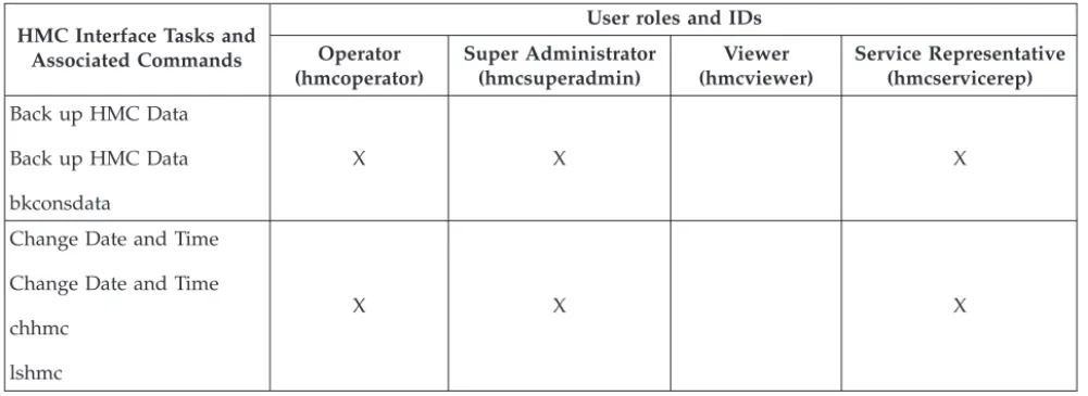
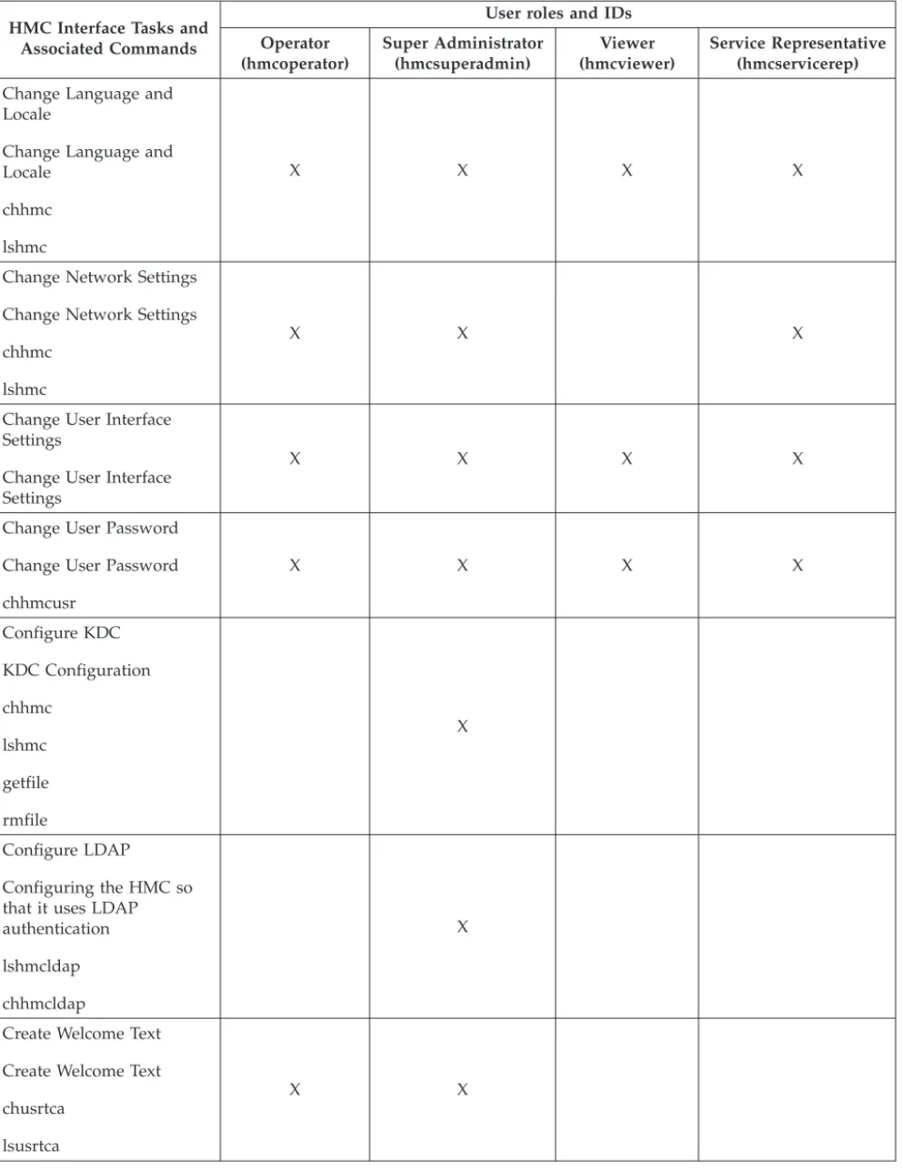
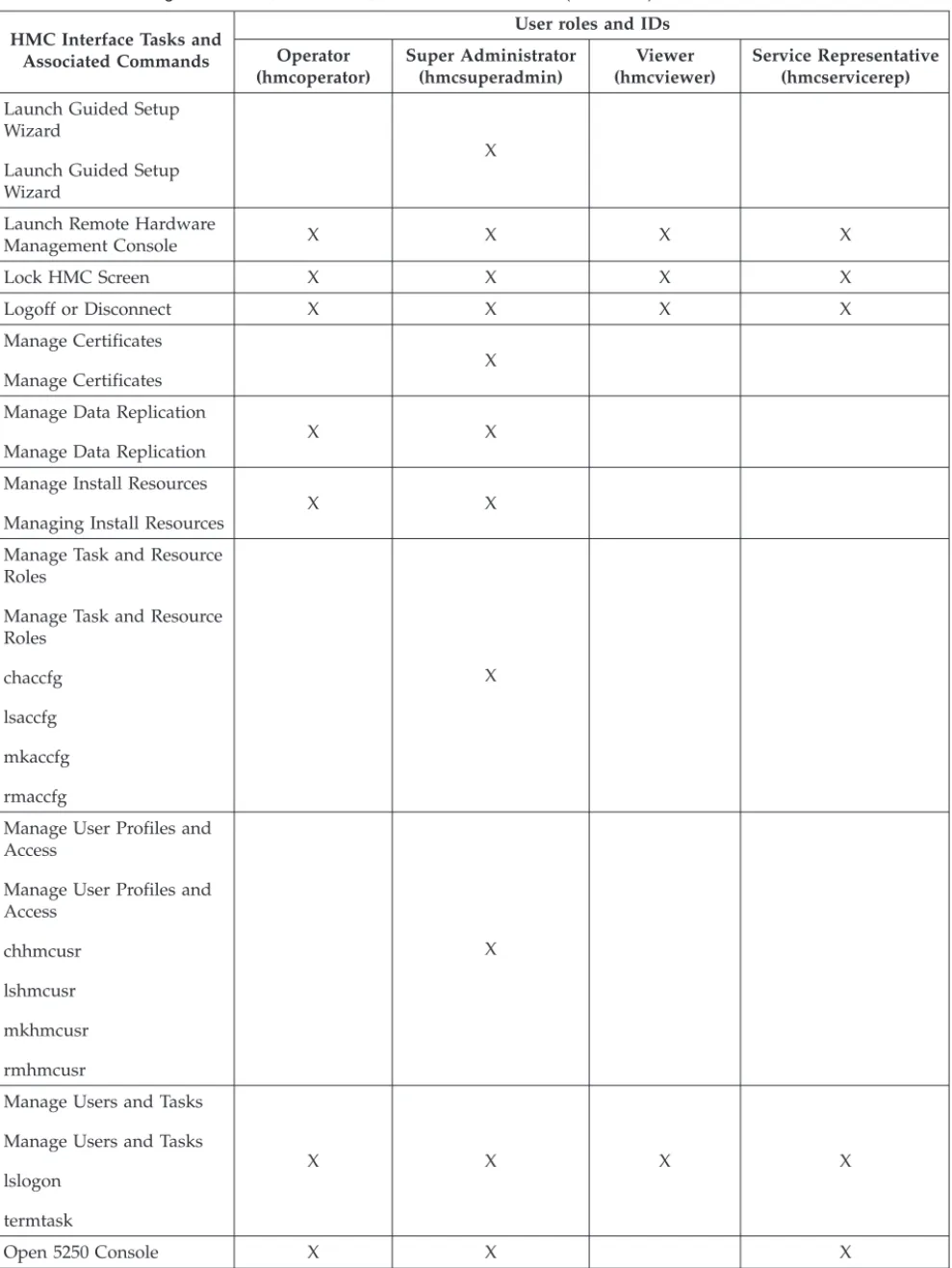
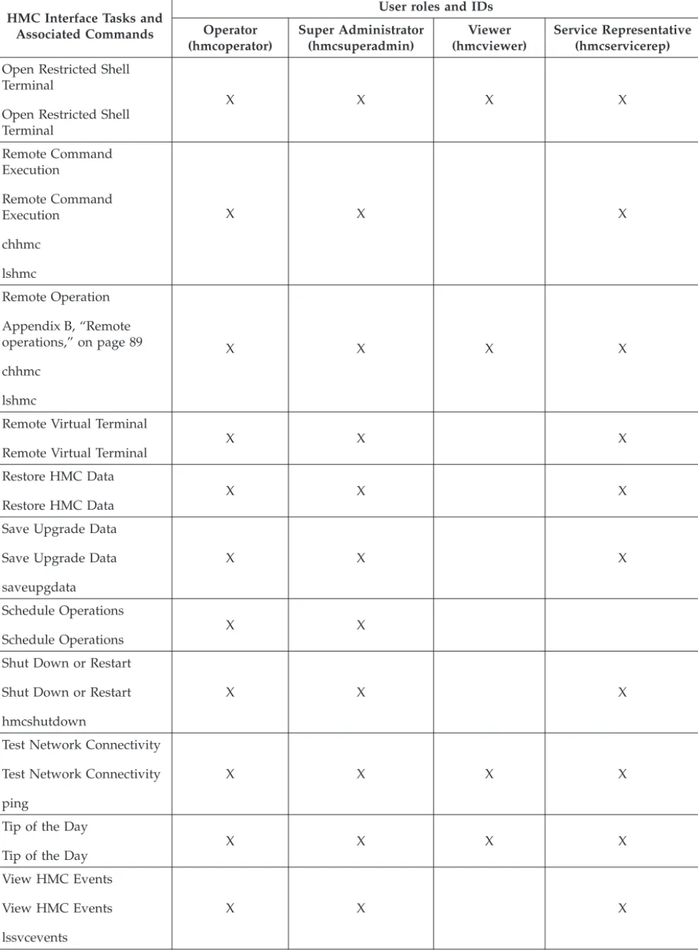
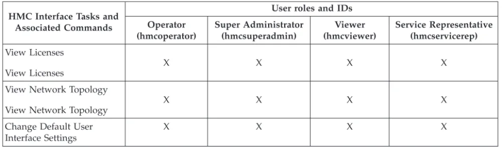
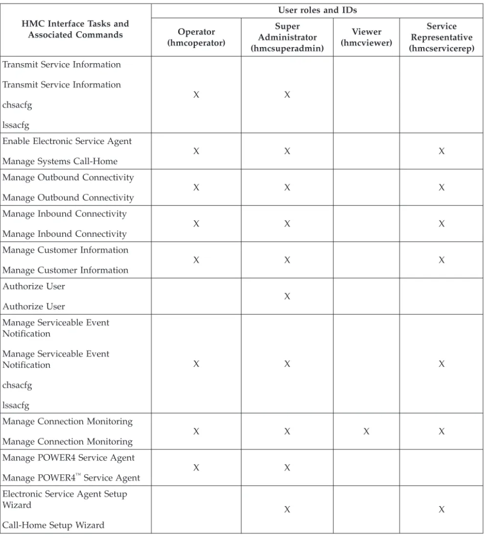
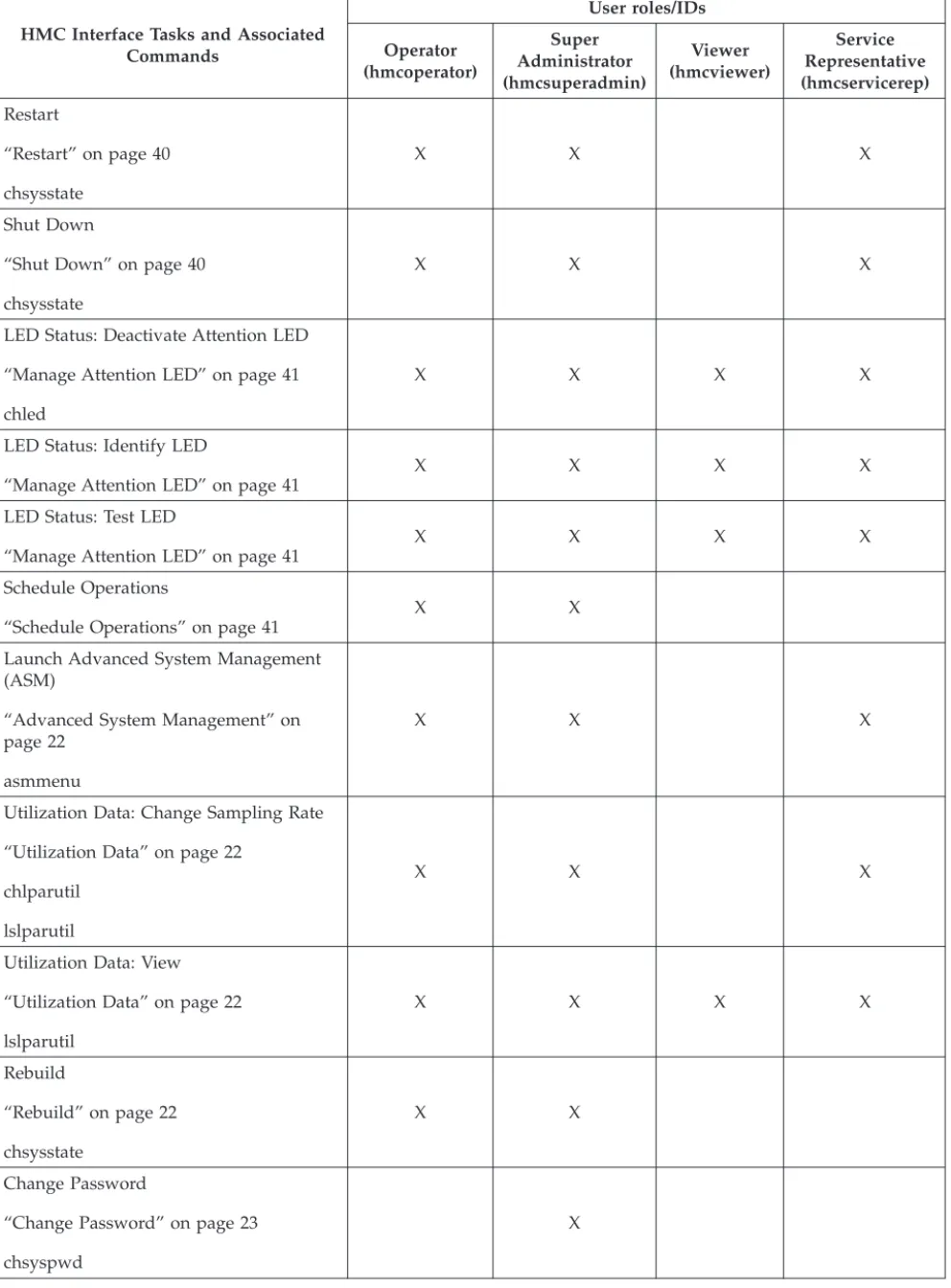
Appendix A. HMC tasks, user roles, IDs, and associated commands . . . 65
Appendix B. Remote operations . . . 89
Using a remote HMC . . . 89
Using a Web browser . . . 90
Using the HMC remote command line . . . 91
Setting up secure script execution between SSH clients and the HMC . . . 91
Enabling and disabling HMC remote commands . . . 92
Web browser requirements . . . 92
Preparing to use the Web browser . . . 92
Logging in to the HMC from a LAN-connected Web browser. . . 92
Appendix C. Customizable data replication . . . 95
Peer-to-Peer replication . . . 95
Master-to-Slave replication . . . 96
Data replication . . . 97
Appendix D. HMC commands . . . 99
Notices . . . 101
Trademarks . . . 102
About this publication
This publication helps users to understand how to use the Hardware Management Console (HMC), describes the tasks you can use on the console, and how to navigate using the web-based user interface.
Note: The HMC user interface windows represented in this document are general samples. They may or may not represent the exact windows that are displayed for your user ID or version.
For information about the accessibility features of this product, for users who have a physical disability, see accessibledoc.dita.
How to send your comments
Your feedback is important in helping to provide the most accurate and highest quality information. If you have any comments about this publication, use theFeedbackbutton at http://www.ibm.com/ systems/infocenter. Alternatively, you can send your comments to [email protected]. Be sure to include the name of the book, the form number of the book, and the specific location of the text you are commenting on (for example, a page number or table number).
Chapter 1. Introduction to the Hardware Management Console
This section briefly describes some of the concepts and functions of the Hardware Management Console (HMC) and introduces the user interface that is used for accessing those functions.
The HMC is a system that controls managed systems, logical partitions, Capacity on Demand (CoD), and updates. To provide flexibility and availability, you can implement HMCs as a local HMC or a redundant HMC.
Local HMC
A local HMC is an HMC that is physically located close to the system it manages and is
connected by either a private or public network. An HMC in a private network is a DHCP server for the service processors of the systems it manages. An HMC may also manage a system over an open network, where the managed system’s service processor IP address has been assigned manually using the Advanced System Management Interface (ASMI).
Remote HMC
A remote HMC is an HMC that is not physically located near its managed systems. This could be in another part of the same room or data center, in another building, or even on another site. Typically, a remote HMC would be attached to its managed servers via a public network, but configurations with a remote HMC attached to a private network are also possible. Prior to HMC version 7, at least one local HMC was required. With Version 7, any or all HMCs may be remote.
Redundant HMC
A redundant HMC manages a system that is already managed by another HMC. When two HMCs manage one system, they are peers, and each can be used to control the managed system. One HMC can manage multiple managed systems, and each managed system can have two HMCs. If both HMCs are connected to the server using private networks, each HMC must be a DHCP server set up to provide IP addresses on two unique, nonroutable IP ranges.
The HMC allows you to configure and manage servers. One HMC can manage multiple servers, and dual HMCs can provide redundant support by managing the same system. To help ensure consistent function, each HMC is shipped preinstalled with the Hardware Management Console Licensed Machine Code Version 7.
User interface style for the HMC
This HMC uses a Web-based user interface. This interface uses a tree style navigation model providing hierarchical views of system resources and tasks to enable direct access to hardware resources and task management capabilities. It provides views of system resources and provides tasks for system
administration.
See Chapter 2, “Using the Web-based user interface,” on page 5 for detailed information on how to use this HMC interface.
Predefined user IDs and passwords
Predefined user IDs and passwords are included with the HMC. It is imperative to your system’s security that you change the hscroot predefined password immediately.
The following predefined user IDs and passwords are included with the HMC:
Table 1. Predefined HMC user IDs and passwords
User ID Password Purpose
hscroot abc123 The hscroot user ID and password are used to log in to the HMC for the first time. They are case-sensitive and can only be used by a member of the super administrator role.
root passw0rd The root user ID and password are used by the service provider to perform maintenance procedures. They cannot be used to log in to the HMC.
Tasks and roles
Each HMC user can be a member of a different role. Each of these roles allows the user to access different parts of the HMC and perform different tasks on the managed system. HMC roles are either predefined or customized.
The roles discussed in this section refer to HMC users; operating systems running on logical partitions have their own set of users and roles. When you create an HMC user, you must assign that user a task role. Each task role allows the user varying levels of access to tasks available on the HMC interface. For more information about the tasks each HMC user role can perform, see Appendix A, “HMC tasks, user roles, IDs, and associated commands,” on page 65.
You can assign managed systems and logical partitions to individual HMC users. This allows you to create a user that has access to managed system A but not to managed system B. Each grouping of managed resource access is called a managed resource role. To learn more about managed resource roles and how to create them, see Manage Task and Resource Roles.
ThepredefinedHMC roles, which are the default on the HMC, are as follows:
Table 2. Predefined HMC Roles
Role Description HMC User ID
Operator The operator is responsible for daily system operation.
hmcoperator
Super Administrator The super administrator acts as the root user, or manager, of the HMC system. The super administrator has unrestricted authority to access and modify most of the HMC system.
hmcsuperadmin
Product Engineer A product engineer assists in support situations, but cannot access HMC user management functions. To provide support access for your system, you must create and
administer user IDs with the product engineer role.
hmcpe
Service Representative A service representative is an employee who is at your location to install, configure, or repair the system.
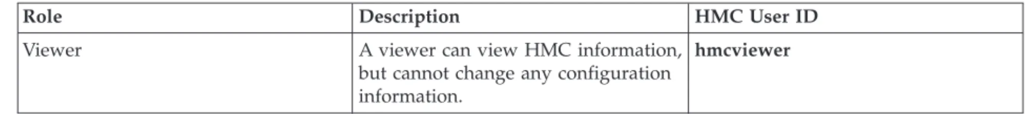
Table 2. Predefined HMC Roles (continued)
Role Description HMC User ID
Viewer A viewer can view HMC information, but cannot change any configuration information.
hmcviewer
You can createcustomizedHMC roles by modifying predefined HMC roles. Creating customized HMC roles is useful for restricting or granting specific task privileges to a certain user. For more information about creating customized HMC roles, see Manage Task and Resource Roles.
Starting the HMC
Turn on the HMC by setting both the display and system unit to theOnposition. The initialization window, which includes the copyright information, is displayed. Learn about how to log in to the HMC interface.
When initialization is complete, the pre-login window is displayed.
Note: The pre-login window contains the link to log in to the HMC application, the ability to view the online help information, and the summarized status information for the HMC. You will need to log in to view the status information.
To log in to the HMC do the following:
1. In the pre-login window, click Log on and launch the Hardware Management Console web application.
2. Enter the user ID and password combination assigned to you.
3. Click Logon.
Note: If you previously disconnected from your session, the Choose a Disconnected Session window opens. Select the session you want to reconnect to and clickReconnect.
After you log in, the HMC workplace window opens and, if enabled, theTip of the Daywindow appears. For more information about how to enable this feature, see Tip of the Day.
The HMC workplace window allows you to work with tasks for your console and managed systems. Not all tasks are available for each user ID. The user role assigned to your user ID determines what tasks you are able to perform. For example, if you are assigned a user ID with the operator role, you will have access to all the tasks that haveoperatoraccess. See Appendix A, “HMC tasks, user roles, IDs, and associated commands,” on page 65 for a listing of all tasks and the user roles for which the tasks are available.
If at any time you do not know or remember what user ID you are currently logged in to the HMC, look at the task bar on the top of the Welcome page or you can clickHMC Managementin the navigation pane. Then clickManage Users and Tasksfrom the work pane (see Manage Users and Tasks for more information).
Chapter 2. Using the Web-based user interface
You can use the Web-based user interface to perform tasks on the Hardware Management Console (HMC) or on your managed resources.
This user interface comprises several major components: the banner, the task bar, the navigation pane, the work pane, and the status bar.
Thebanner, across the top of the workplace window, identifies the product and logo. It is optionally displayed. Use theChange User Interface Settingstask to change the setting.
Thetask bar, located below the banner, displays the names of any tasks that are running, the user ID you are logged in as, online help information, and the ability to logoff or disconnect from the console.
Thenavigation pane, in the left portion of the window, contains the primary navigation links for managing your system resources and the HMC. The items are referred to as nodes.
Thework pane, in the right portion of the window, displays information based on the current selection from the navigation pane. For example, whenWelcomeis selected in the navigation pane, the Welcome window content is displayed in the work pane.
Thestatus bar, in the bottom left portion of the window, provides visual indicators of current overall system status. It also contains a status overview icon which may be selected to display more detailed status information in the work pane.
You can resize the panes of the HMC workplace by moving the mouse pointer over the border that separates the navigation pane from the work pane until the mouse pointer changes to a double-pointed arrow. When the pointer changes shape, press and hold the left mouse button while dragging the mouse pointer to the left or right. Release the button and your navigation pane or work pane is now larger or smaller in size. You can also do this within the work pane border that separates the resources table from the tasks pad.
Task bar
The Task bar contains the Help and Logoff tasks and a button that represents each currently running task.
Navigation pane
The Navigation pane contains the primary links for managing your system resources and the HMC. These include Systems Management, System Plans, HMC Management, and Service Management.
Systems Management
Systems Management contains a view of system resources such as servers, frames, and Custom groups. Custom groups include the predefined groups ’All Partitions’, ’All Objects’, and any user-defined groups.
System Plans
HMC Management
HMC Management contains categorized HMC management tasks. Related tasks are categorized
alphabetically by links including HMC and user customization, console tasks, connectivity, and settings.
Service Management
Service Management contains a categorized or alphabetic view of tasks and their descriptions used to service the Hardware Management Console.
Updates
Updates provides a way for you to access information on both HMC and system firmware code levels at the same time without running a task.
Welcome
Welcome is the initial window that is displayed when you log on to the HMC.
The Welcome work pane lists the nodes of the navigation pane and their descriptions. It also includes the following Additional Resources:
Guided Setup Wizard
Provides a step-by-step process to configure your HMC.
HMC Operations Guide
Provides an online version of theManaging the HMCfor system administrators and system operators using the HMC.
If you are accessing the HMC remotely, you can view the publication in PDF format or in HTML format (clickView as HTML). If you are accessing the HMC locally, you can view the publication in HTML format.
HMC Readme
Provides hints and errata information about the HMC.
Online Information
Provides information about the HMC.
Note: The following information is only available when you are accessing the HMC remotely.
IBM® System Support
supplies support and technical information for IBM Systems
HMC Support
supplies support and technical information for the HMC
Education and Tutorials
supplies course materials for training and updating HMC skills
To see what level of the HMC you are currently using, point your mouse overHMC Versionat the top of the work pane.
Systems Management
Systems Management contains a tree view of managed resources. Resources may include Servers, Frames, and Custom Groups.
Servers
To add servers, you can use theAdd Managed Systemtask under theConnectionscategory in the tasks pad.
When you clickServersfrom the navigation pane a listing of individually defined servers is displayed in table form in the work pane, and under theServersnode in the navigation pane.
Selecting a server:
Learn about the information displayed when you select a server. To work with a server, you can perform one of the following actions:
v Select a server under theServersnode from the navigation pane. v Click on a server name from the work pane table.
v Click in theSelectcolumn next to the server name in the work pane table.
The Servers work pane table displays the following attributes by default.
Name Specifies the user-defined name of the managed system.
Status Displays the current status of the managed system (for example, Operating, Power off, Initializing) and, in addition, displays icons representing an unacceptable state or an active Attention LED. See “Status: Unacceptable” on page 15 or “Status: Attention LEDs” on page 15 for more information.
Available Processing Units
Displays the number of processing units that are available for assignment to logical partitions on the managed system. This is the total number of processing units that are activated on the managed system minus the number of processing units that are assigned to the logical partitions, including the logical partitions that are shut down, on the managed system. This number does not include any processing units that have not yet been activated with Capacity on Demand (CoD).
Available Memory
Displays the amount of memory that is available for assignment to logical partitions on the managed system. This is the total amount of memory that is activated on the managed system minus the amount of memory needed by managed system firmware minus the amount of memory that is assigned to the logical partitions, including the logical partitions that are shut down, on the managed system. This number does not include any memory that has not yet been activated with Capacity on Demand (CoD). The available memory amount can be shown in MB or GB. ClickMBorGB in the Available Memory column title.
Reference Code
Displays the system reference codes for the server. Click the reference code in the table for a detailed description.
The Servers work pane table can also display the following optional attributes in the table.
Configurable Processing Units
Displays the configured processing units. Configured - Licensed and usable (not guarded) processing units.
Configurable Memory
Displays the configured memory. Configured - Licensed and usable (not guarded) memory.
Serial Number
Displays the serial number of the managed system.
Type-Model
CoD Processor Capable
Displays whether the managed system supports Capacity on Demand (CoD) for processors.
CoD Memory Capable
Displays whether the managed system supports CoD for memory.
Permanent Processors
Specifies the number of permanent licensed processors.
On/Off CoD Processors State
Displays the On/Off CoD processor state.
Trial CoD Processor State
Displays the Trial CoD processor state.
Reserved CoD Processor State
Displays the Reserved CoD processor state.
Utility CoD Processor State
Displays the Utility CoD processor state.
Permanent Memory (GB)
Displays the amount of permanent activated memory.
On/Off CoD Memory State
Displays the On/Off CoD memory state.
Trial CoD Memory State
Displays the Trial CoD memory state.
To show optional attributes, select theColumn configurationicon on the table toolbar. This function allows you to select additional attributes that you want displayed as columns in the table. It also allows you to reorder the columns, see “Column configuration” on page 14 for more information.
You can also useViews from the table toolbar to display theDefaultserver attributes in the table or to display theCapacity On Demandserver attributes in the table. See “Views menu” on page 14 for more information.
Displaying server details:
Display a server’s properties.
To display details (properties) about a server, you can select the server by clicking in theSelectcolumn in the work pane table. Then you can either clickPropertiesfrom the tasks pad or click on the
double-arrow icon next to the server name and clickPropertiesfrom the context menu. In both cases, the Properties window opens.
Launching tasks for managed objects:
After you have chosen the objects to work with, you are ready to perform the appropriate tasks on them. Learn about how to launch a task for your selected managed objects.
Appropriate tasks for a selected object are listed in the tasks pad, in context menus, and in theTasks
menu.If a particular task cannot be performed on an object, the task will not display.
Tasks pad:
The Tasks pad appears below the Work pane when you have selected an object you want to work with. This view contains available tasks for selected managed object(s).
v Tasks are available for the currently selected target object(s) in the Navigation pane tree or the Work
pane table view. If multiple objects are selected in the Work pane table, the intersection of the selected objects’ tasks is displayed. If there are no selections in the table, tasks are displayed for the object selected in the Navigation pane.
v Tasks available are limited by the role of the currently logged in user
The Tasks pad is optionally displayed and is set by using the Change User Interface Settings task. The following is an example of using the Tasks pad method:
1. In the Work pane table, select a server.
2. In the Tasks pad, select a task group by clicking on the expand button or clicking on the group name.
3. Select a task that appears under the task group that you want to perform on that server. The task window opens.
Context Menu:
TheContext menulists the task groups appropriate for the selected object. Context menus are available only for table selections. For example, in theSelectcolumn of the Servers Work pane table, select the object you want to work with. The Context menu button (double right arrows) appears next to the object name you have selected. Click the button and the task groups menu appears for that particular object. Then select a task. If more than one object is selected, the tasks that appear in the Context menu(s) apply to all selections.
Tasks menu:
The tasks menu is displayed on the table toolbar.
The tasks menu is available only for table selections. For example, in theSelectcolumn of the Servers work pane table, select the object you want to work with. ClickTasksfor the list of the applicable task groups for the selected objects in the table. Select a task group, then select a task to open for the object. If more than one object is selected, the tasks that are displayed in the tasks menu apply to all selections.
Partitions:
When you select a managed server in the navigation pane, the work pane displays the list of partitions defined on the server.
The Partitions work pane table displays the following attributes by default:
Name Specifies the user-defined name of the logical partition.
ID Specifies the ID of the partition
Status Displays the current status of the partition (for example, running, not activated) and, in addition, displays icons representing an unacceptable state or active Attention LED. See “Status:
Unacceptable” on page 15 or “Status: Attention LEDs” on page 15 for more information.
Processing Units
Displays the unit of measure for shared processing power across one or more virtual processors. Processing power can be specified in fractions of a processor.
Memory
Specifies the amount of memory allocated to the partition currently. The memory amount can be shown in MB or GB. ClickMBorGBin the Memory column title.
Active Profile
Environment
Specifies the type of object, logical partition, server, frame.
Reference Code
Displays the system reference codes for the partition. For POWER6® systems, click the reference code in the table for a detailed description.
The Partitions work pane table can also display the following optional attributes in the table.
Processor
If the partition is using dedicated processors, this value indicates the number of processors currently allocated to the partition. If the partition is using shared processors, this value represents the virtual processors currently allocated to the partition.
Service Partition
Specifies whether the partition has service authority.
Configured
Specifies whether a partition is configured with all the required resources to power on.
Default Profile
Specifies the profile that is configured as the default profile. When users perform theActivate
task from the partition, this profile is selected by default.
Optional attributes can be displayed when you select theColumn configurationicon on the table toolbar. This function allows you to select additional attributes that you want displayed as columns in the table. It also allows you to reorder the columns, see “Column configuration” on page 14 for more information.
Displaying partition details:
Display a partition’s properties.
To display details (properties) about a partition you can select the partition by clicking in theSelect
column in the work pane table. Then you can either clickPropertiesfrom the tasks pad or click on the double-arrow icon next to the partition name and clickPropertiesfrom the context menu. You can also click on the partition name. In all cases thePropertieswindow is displayed.
Frames
TheFramesnode identifies the frames managed by this HMC.
Frames typically have dual Bulk Power Controllers (BPCs), however only one BPC is displayed as both BPCs share the same machine type, model, and serial number and function as redundant peers.
The Frames work pane table includes the following attributes:
Name Displays the defined name of the Frame.
Status Displays the status of the frame object. A frame is in an unacceptable state when it is inNo ConnectionorIncompletestate. When either of these conditions occurs, a red X is displayed in the status cells next to the status text which identifies the state. Clicking on either the X or the status text opens information describing the unacceptable state and potential remedies.
Frame Number
Displays the number of the managed frame. You can modify the number.
Connection Status
Displays connection status of the frame (side A and B).
Custom Groups
TheCustom Groupsnode provides a mechanism for you to group system resources together in a single view.
Groups may be nested to create custom″topologies″of system resources.
Custom groups include the predefined groupsAll PartitionsandAll Objectsand any user-defined groups that you created using theManage Custom Groupstask under theConfigurationcategory in the tasks pad. TheAll Partitions group includes all the partitions defined to all servers managed by the HMC. TheAll Objectsgroup is a collection of all the managed servers, partitions, and frames.
These system-defined groups (All Partitions and All Objects) cannot be deleted. However, if you do not wantAll PartitionsorAll Objectsdisplayed under Custom Groups, do the following:
1. Open the Change User Interface Settingstask from the HMC Management work pane.
2. Deselect All Partitions nodeandAll Objects nodein theUser Interface Settingswindow.
3. Click OKto save the changes and close the window. Those groups are no longer displayed under
Custom Groupsin the navigation pane.
You can use theViewsmenu on the table toolbar to display your preferred table column configuration. For more information, see “Views menu” on page 14.
User-defined groups:
Create new groups and manage existing ones.
ClickManage Custom Groupstask under the Configuration category from the tasks pad to create your own group that you want to work with.
To create a group, do the following:
1. Select one or more resources (for example: servers, partitions, frames) that you want to include in the group you want to work with.
2. Click Manage Custom Groups.
3. SelectCreate a new group, specify a group name and description, and then clickOK. The new user-defined group is displayed in the navigation pane underCustom Groups.
You can also create a group by using the pattern match method. To use the pattern match method, do the following:
1. Without selecting an object, clickManage Custom Groupsfrom the Custom Groups or Systems Management tasks pad.
2. From the Create Pattern Match Group window, select one or more group types that you want to create, specify a group name, description, and the pattern used to determine if an object should be part of the group. Click OKto complete. The new user-defined group is displayed in the navigation pane under theCustom Groupsnode.
Note: Patterns specified in theManaged Resource Pattern input field are regular expressions. For example, if you specifiedabc.*, all the resources that begin withabcwill be included in that group. For more information, see “Manage Custom Groups” on page 24.
System Plans
You can display the plans and the tasks used to deploy system plans to managed systems.
Asystem plancontains a specification of the logical partition configuration of a single managed system. You can also use this node to import, export, and manage the files containing these system plans. To display the plans and tasks:
1. In the navigation pane, selectSystem Plans.
3. From the tasks pad, click one of the following tasks:
v Create System Plan v Deploy System Plan v Export System Plan v Import System Plan v Remove System Plan v View System Plan
These tasks are described in further detail in “System Plans” on page 23. The table in the work pane displays the system plans that the HMC manages and attributes related to the system plans.
The following attributes are set as the defaults. However, you can select or deselect the attributes that you want displayed in the table by clicking theColumn configurationicon on the table toolbar. You can also reorder the columns. For more information, see “Column configuration” on page 14.
Name Displays the system plan file name.
Description
Specifies a description of the system plan.
Source
Displays how the system plan was created.
Version
Displays version information about the system plan.
Last Modified Date
Specifies the date when the system plan was last modified.
The create and deploy System Plans tasks are also displayed for a server under theConfiguration task group.
If there are no system plans available when you selectSystem Plans, you can create or import a plan from the tasks listed in the tasks pad.
HMC Management
HMC Management contains a categorized view of HMC management tasks and their descriptions. These tasks are used for setting up the HMC, maintaining its internal code, and securing the HMC. To display the tasks in the work pane, do the following:
1. In the Navigation pane, selectHMC Management.
2. In the work pane, click on the task you want to perform.
3. By default, a categorized listing of the tasks is displayed. The categories include:
v Operations v Administration
To see the HMC level you are using, point your mouse overHMC Versionat the top of the work pane. If you want an alphabetic listing of the tasks, clickAlphabetical Listin the upper right corner of the work pane. ClickCategorized Listto go back to the task categories.
Note: If you are accessing the HMC remotely, some tasks do not display.
HMC Management tasks are described in further detail in HMC Management tasks and a listing of the tasks and the default user roles that can use them are shown in Table 4 on page 65.
Service Management
Service Management contains a categorized or alphabetic view of tasks and their descriptions used to service the HMC.
To display the tasks in the work pane, do the following:
1. In the Navigation pane, selectService Management.
2. In the work pane, click on the task you want to perform.
3. By default, a categorized listing of the tasks appear. The category is Connectivity.
To see the HMC level you are using, point your mouse overHMC Versionat the top of the work pane. If you want an alphabetical listing of the tasks, clickAlphabetical Listin the upper right corner of the work pane. ClickCategorized Listto go back to the task categories.
Service Management tasks are described in further detail in Service Management tasks and a listing of the tasks and the default user roles that can use them are shown in Table 4 on page 65.
Updates
Updates provides a way for you to access information on both HMC and system firmware code levels at the same time without performing a task.
TheUpdateswork pane displays the HMC code level, and system code levels. You can also install corrective service by clickingUpdate HMC.
Note: Before performing HMC updates, see “Update HMC” on page 61. To display the tasks, do the following:
1. In the navigation pane, selectUpdates.
2. Select a managed object.
3. In the tasks pad, click the task you want to perform.
These tasks can also be viewed under theUpdatestask group when you are working with managed objects displayed inSystems Management.
Work pane
The Work pane displays information based on the current selection in the Navigation pane or Status bar. For example, when you click an individual server, the Navigation pane displays a configurable table in the Work pane that displays a list of all the managed systems on that server.
Task pad
Selecting a task can be done in a number of ways. Tasks for selected objects are listed in the Work pane, Tasks pad, context menus, and in the Tasks drop-down menu on the table toolbar. When context sensitive tasks are listed at the bottom of the Work pane in the Tasks pad, only tasks applicable for selected objects are displayed.
Working with Tables
The tool bar at the top of the table contains buttons used to select, filter, sort, and arrange the entries in the table.
Hovering over the toolbar buttons displays their functions. The toolbar also includes menus that are used with the information displayed in the tables. For more information, see “Tasks menu” on page 9 and “Views menu” on page 14.
Selecting Rows
You can select more than one table row at a time.
Rows can be individually selected or a block of rows can be selected at once by first left-clicking the selection box of the first row in the desired block and then shift-clicking the selection box of the last row in the desired block. TheSelect AllorDeselect Allbuttons can be used to select or deselect all objects in the table. The table summary at the bottom of the table includes the total number of items that are selected.
Filtering
Learn more about how to define a filter for a column to limit the entries displayed in a table.
If you select theFilter Rowbutton a row appears under the title row of the table. SelectFilterunder a column to define a filter for that column to limit the entries in a table. Tables can be filtered to show only those entries most important to you. The filtered view can be toggled on and off by selecting the check box next to the desired filter in the filter row. Select theClear All Filtersbutton to return to the complete listing. The table summary includes the total number of items that pass the filter criteria in addition to the total number of items.
Sorting
The Edit Sort and Clear All Sorts buttons are used to perform multi-column sorts of objects in the table in ascending or descending order.
ClickEdit Sortto define sorts for columns in a table. Alternatively, single column sorting can be
performed by selecting the ^ in the column header to change from ascending to descending order. Click
Clear All Sortsto return to the default ordering.
Column configuration
The column configuration buttons give you the ability to select which columns to display for folders in the Systems Management tree view.
Click theConfigure Columnsbutton to arrange the columns in the table in a desired order or hide columns from view. All available columns are listed in the Columns list box by their column name. You select the columns you want displayed or hidden by checking or unchecking the box next to the column names. The column order is manipulated by clicking on a column name from the list box and using the arrow buttons to the right of the list to change the order of the selected column. When you have
completed the configuration of the columns, clickOK. The columns appear in the table as you specified. If you want to go back to the original layout of the table, click theReset Column Order, Visibility, and Widthsbutton from the table toolbar. Select one or more of the properties you want to reset. ClickOKto save this setting.
Views menu
The Views menu is displayed on the toolbar and is only available for table selections when working with servers, custom groups, exceptions view, or attention LEDs view.
This table option allows you to display different sets of attributes (columns) in the table. You can also change the attributes for each view.
Status bar
The status bar in the bottom left pane provides a view of overall system status, including managed system resources and the HMC.
A status-sensitive title, background color, and indicator icons are part of the status bar. The status indicators appear in color when one or more objects go into unacceptable status, have attention LEDs, or have open serviceable events. Otherwise, the status icon is not available.
Click any of the individual icons in the status bar to view a listing of resources with specific status. For example, select the Unacceptable icon to view all resources in an unacceptable state. The results are displayed in a table in the work pane.
Status: Unacceptable
If any managed object is in unacceptable state, the Unacceptable indicator displays on the status bar. When you select theUnacceptableindicator, it displays a table in the work pane of only the objects in an unacceptable state. By clicking on the icon, help information is opened describing the status of the server or partition. You can also use theViews menu to display your preferred table column configuration for these objects.
Status: Attention LEDs
If any managed object’s Attention LED is activated, the Attention LED icon displays in the status bar. When you select the Attention LED icon it displays a table in the work pane of only the objects in Attention LED. A help window opens when you click on the icon. You can also use theViewsmenu to display your preferred table column configuration for these objects.
Status: Serviceable Events
If at least one serviceable event for the HMC or a managed object is in an open state, the serviceable event icon displays in the status bar.
When you click the icon theManage Serviceable Eventswindow opens. This window displays all open events.
Status Overview
The Status Overview icon displays a detailed summary of system status in the work pane.
TheStatus Overviewicon displays details about any errors, attention LEDs active, or open serviceable events found for the HMC or managed objects. It also summarizes the total number of errors, attention LEDs, and open serviceable events by object type. Object types include the server, partition, frames, and the HMC. When any of these conditions are present, links are available to display all objects with the particular state in the work pane.
Chapter 3. Systems Management for Servers
Systems Management displays tasks to manage servers, logical partitions, and frames. Use these tasks to set up, configure, view current status, troubleshoot, and apply solutions for servers.
To perform these tasks, see “Launching tasks for managed objects” on page 8. The tasks listed in the tasks pad change as selections are made in the work area. The context is always listed at the top of the tasks pad in the formatTask: Object. These tasks are listed when a managed system is selected.
Properties
Display the selected managed system’s properties. This information is useful in system and partition planning and resource allocation.
These properties include the following:
General
TheGeneraltab displays the system’s name, serial number, model and type, state, attention led state, service processor version, maximum number of partitions, assigned service partition (if designated), and power off policy information.
Processor
TheProcessortab displays information about the managed system’s processors including
installed processing units, deconfigured processing units, available processing units, configurable processing units, minimum number of processing units per virtual processor and maximum number of shared processor pools.
Memory
TheMemorytab displays information about the managed system’s memory including installed memory, deconfigured memory, available memory, configurable memory, memory region size, current memory available for partition usage, and system firmware current memory. A tab describes the maximum number of memory pools.
I/O TheI/Otab displays the physical I/O resources for the managed system. The assignment of I/O slots and partition and adaptor-type information are displayed, grouped by units. Select the link in theSlot column to display the physical I/O properties of each resource. SelectI/O Poolsto display all of the I/O pools found in the system and the partitions that are participating in the pools.
Migration
If your managed system is partition-migration capable, theMigrationtab displays partition migration information.
Power-On Parameters
ThePower-On Parameterstab displays the initial program load (IPL) source mode for restarting, and allows you to change the power-on parameters for the next restart by changing the values in the Next fields. These changes will only be valid for the next managed system restart.
Capabilities
TheCapabilitiestab displays the runtime capabilities of this server. SelectHelpfor more information on the capabilities listed.
Advanced
TheAdvancedtab displays huge page memory capabilities on the managed system, including available huge page memory, configurable huge page memory, current page size, and current maximum huge page memory. To change memory allocation on systems with huge page table support, set the Requested huge page memory (in pages) field to the desired memory. To change
the requested value for huge page memory, the system must be powered off. The Barrier Synchronization Register (BSR) displays array information.
Update Password
Use the Update Password task to update HMC access and Advanced System Management Interface (ASMI) passwords on the managed system.
The first time you access a managed system using an HMC, the system prompts you to enter passwords for each of the following:
v Hardware Management Console: HMC access v Advanced System Management Interface: General v Advanced System Management Interface: Admin
If you are using an HMC to access the managed system before all required passwords have been set, enter the appropriate password for each password that is presented in the Update Password task.
If another HMC subsequently needs access to this managed system, upon attempting to access this HMC the user is presented with the Update Password Failed Authentication window, which will prompt for the HMC access password you entered.
In the event that the HMC access password changes while you are logged in to the managed system, your HMC will discover that it can no longer authenticate after it attempts to reconnect to that managed system. This will result in a state ofFailed Authenticationfor that managed system. You will be required to enter the new password before any actions can be performed.
Operations
Operations contains the tasks for operating managed systems.
Power On
Use thePower Ontask to start a managed system.
Choose from the following options to power on your managed system:
Normal:Select this option to specify that the HMC uses the current setting for the partition start policy to determine how to power on the managed system. The current setting can be one of the following values:
v Auto-Start Always: This option specifies that the HMC power on logical partitions automatically after
the managed system powers on. If powering on the managed system is the result of a user action, the HMC starts all partitions that are configured for automatic start up. If powering on the managed system is the result of an automatic recovery process, the HMC starts only those logical partitions that were running at the time the system powered off. This option is always available for selection.
v Stop at Partition Standby: This option specifies that logical partition start up is in standby mode after
the managed system powers on and the HMC does not start any logical partitions when the managed system powers on. If powering on the managed system is the result of an automatic recovery process and the HMC is used to start a logical partition, the HMC starts all logical partitions that were running at the time the system powered off. This option is available for selection only when the firmware for the managed system does not support advanced IPL capabilities.
v Auto-Start for Auto-Recovery: This option specifies that the HMC power on logical partitions
automatically only after the managed system powers on as the result of an automatic recovery process. This option is available for selection only when the firmware for the managed system supports this advanced IPL capability.
v User-Initiated: This option specifies that the HMC does not start any logical partitions when the
managed system powers on. You must start logical partitions manually on the managed system by using the HMC. This option is available for selection only when the firmware for the managed system supports this advanced IPL capability.
You can set the partition start policy from the Power On Parameters page of the Properties task for the managed system.
System profile: Selecting this power-on option specifies that the HMC power on the system and its logical partitions based on a predefined system profile. When you select this power-on option, you must select the partition profile that you want the HMC to use to activate logical partitions on the managed system.
Hardware Discovery: Selecting this power-on option specifies that the HMC run the hardware discovery process when the managed system powers on. The hardware discovery process captures information about all I/O devices -- in particular those devices not currently assigned to partitions. When you select the hardware discovery power on option for a managed system, the managed system is powered on into a special mode which performs the hardware discovery. After the Hardware Discovery process is
complete, the system will be in Operating state with any partitions in the power-off state. The Hardware Discovery process records the hardware inventory in a cache on the managed system. The collected information is then available for use when displaying data for I/O devices or when creating a system plan based on the managed system. This option is available only if the system is capable of using the hardware discovery process to capture I/O hardware inventory for the managed system.
Power Off
Shut down the managed system. Powering off the managed system will make all partitions unavailable until the system is again powered on.
Before you power off the managed system, ensure that all logical partitions have been shut down and that their states have changed fromRunningtoNot Activated. For more information on shutting down a logical partition, see “Shut Down” on page 40
If you do not shut down all logical partitions on the managed system before you power off the managed system, the managed system shuts down each logical partition before the managed system itself powers off. This can cause a substantial delay in powering off the managed system, particularly if the logical partitions are not responsive. Further, the logical partitions might shut down abnormally, which could result in data loss and further delays when you activate the logical partitions once more.
Choose from the following options:
Normal power off
The Normal power off mode shuts down the system’s operations in a controlled manner. During the shutdown, programs running active jobs are allowed to perform cleanup (end-of-job
processing).
Fast power off
The Fast power off mode shuts down the system by stopping all active jobs immediately. The programs running those jobs are not allowed to perform any cleanup. Use this option when you need to shut down the system because of an urgent or critical situation.
Power Management
You can reduce the manage system’s processor power consumption by enabling power saver mode. To enable power saver mode, do the following:
2. In the navigation area, expandServers.
3. Select the server that you want to enable to use power saver mode.
4. In the tasks area, expandOperations.
5. ClickPower Management.
6. Select your desired power saver mode, and clickOK.
LED Status
View system attention LED information, light specific LEDs to identify a system component, and test all LEDs on a managed system.
The system provides several LEDs that help identify various components, such as enclosures or field replaceable units (FRUs), in the system. For this reason, they are calledIdentifyLEDs. Individual LEDs are located on or near the components. The LEDs are located either on the component itself or on the carrier of the component (for example, memory card, fan, memory module, or processor). LEDs are either green or amber. Green LEDs indicate either of the following:
v Electrical power is present.
v Activity is occurring on a link. (The system could be sending or receiving information.)
Amber LEDs indicate a fault or identify condition. If your system or one of the components on your system has an amber LED turned on or blinking, identify the problem and take the appropriate action to restore the system to normal.
You can activate or deactivate the following types of identify LEDs:
Identify LED for an enclosure
If you want to add an adapter to a specific drawer (enclosure), you need to know the machine type, model, and serial number (MTMS) of the drawer. To determine whether you have the correct MTMS for the drawer that needs the new adapter, you can activate the LED for a drawer and verify that the MTMS corresponds to the drawer that requires the new adapter.
Identify LED for a FRU associated with a specified enclosure
If you want to attach a cable to a specific I/O adapter, you can activate the LED for the adapter that is a field replaceable unit (FRU), and then physically verify where to attach the cable. This can be especially useful when you have several adapters with open ports.
You can deactivate a system attention LED or a logical partition LED. For example, you might determine that a problem is not a high priority and decide to repair the problem at a later time. However, you want to be alerted if another problem occurs, so you must deactivate the system attention LED so that it can be activated again if another problem occurs.
Choose from the following options:
Identify LED
Displays the current Identify LED states for all the location codes contained in the selected enclosure. From this task, you can select a single location code or multiple location codes to operate against and activate or deactivate the LED(s) by selecting the corresponding button.
Test LED
Initiates an LED Lamp Test against the selected system. All LEDs will activate for several minutes.
Schedule Operations
Create a schedule for certain operations to be performed on the managed system without operator assistance.
Scheduled operations are helpful for situations where automatic, delayed, or repetitious processing of system operations is necessary. A scheduled operation is started at a specified time, without operator assistance to perform the operation. A schedule can be set for one operation or repeated many times. For example, you could schedule power on or off operations for a managed system.
The Scheduled Operations task displays the following information for each operation:
v The processor that is the object of the operation. v The scheduled date
v The scheduled time v The operation
v The number of remaining repetitions
From the Scheduled Operations window you can do the following:
v Schedule an operation to run at a later time v Define operations to repeat at regular intervals v Delete a previously scheduled operation
v View details for a currently scheduled operation
v View scheduled operations within a specified time range
v Sort scheduled operations by date, operation, or managed system
You can schedule an operation to occur once or you can schedule it to repeat. You must provide the time and date that you want the operation to occur. If the you want the operation to repeat, you will be asked to select the following:
v The day or days of the week that you want the operation to occur. (optional) v The interval, or time between each occurrence. (required)
v The total number of repetitions. (required)
The operations that you can schedule for the managed system include the following:
Activate on a System Profile
Schedules an operation on a selected system for scheduling activation of a selected system profile.
Backup Profile Data
Schedules an operation to back up profile data for a managed system
Power Off Managed System
Schedules an operation for a system power off at regular intervals for a managed system.
Power On Managed System
Schedules an operation for a system power on at regular intervals for a managed system.
Manage Utility CoD processors
Schedules an operation for managing how your Utility CoD processors are used.
Manage Utility CoD processor minute usage limit
Creates a limit for Utility CoD processor usage.
Modify a Shared Processor Pool
Schedules an operation for modifying a shared processor pool.
Move a partition to a different pool
Schedules an operation for moving a partition to a different processor pool.
Change power saver mode on a managed system
Schedules an operation for changing a managed system’s power saver mode. To schedule operations on the managed system, do the following:
1. In the Navigation area, clickSystems Management.
3. In the work pane, select one or more managed systems.
4. In the tasks pad, select theOperationstask category, then clickSchedule Operations. The Customize Scheduled Operations window opens.
5. From the Customize Scheduled Operations window, click Optionsfrom the menu bar to display the next level of options:
v To add a scheduled operation, clickOptionsand then clickNew....
v To delete a scheduled operation, select the operation you want to delete, point toOptionsand then
clickDelete.
v To update the list of scheduled operations with the current schedules for the selected objects, point
toOptionsand then clickRefresh.
v To view a scheduled operation, select the operation you want to view, point toViewand then click
Schedule Details....
v To change the time of a scheduled operation, select the operation you want to view, point toView
and then clickNew Time Range....
v To sort the scheduled operations, point toSort and then click one of the sort categories that
appears.
6. To return to the HMC workplace, point toOperations and then clickExit.
Advanced System Management
The HMC can connect directly to the Advanced System Management (ASM) interface for a selected system.
ASM is an interface to the service processor that allows you to manage the operation of the server, such as auto power restart, and to view information about the server, such as the error log and vital product data.
To connect to the Advanced System Management interface, do the following:
1. From theSystem Managementtasks list, selectOperations.
2. From the Operationstask list, selectAdvanced System Management (ASM).
Utilization Data
You can set the HMC to collect resource utilization data for a specific managed system or for all systems the HMC manages.
The HMC collects utilization data for memory and processor resources. You can use this data to analyze trends and make resource adjustments. The data is collected into records called events. Events are created at the following times:
v At periodic intervals (30 seconds, 1 minute, 5 minutes, 30 minutes, hourly, daily, and monthly) v When you make system-level and partition-level state and configuration changes that affect resource
utilization
v When you start up, shut down, and change the local time on the HMC
You must set the HMC to collect utilization data for a managed system before utilization data can display for the managed system.
Use theChange Sampling Ratetask to enable, set and change the sampling rate, or disable sampling collection.
Rebuild
You can extract the configuration information from the managed system and rebuild the information on the Hardware Management Console (HMC).
This task does not disrupt the operation of the running server.
Rebuilding the managed system updates the information on the HMC about the managed system. Rebuilding the managed system is useful when the state of the managed system isIncomplete. The Incomplete state means that the HMC cannot gather complete information from the managed system about logical partitions, profiles, or resources.
Rebuilding the managed system is different from refreshing the HMC window. When the managed system is rebuilt, the HMC extracts the information from the managed system. You cannot start other tasks while the HMC rebuilds the managed system. This process can take several minutes.
Change Password
Change the HMC access password on the selected managed system
After the password is changed, you must update the HMC access password for all other HMCs from which you want to access this managed system.
Enter the current password. Then enter a new password and verify it by entering it again.
Configuration
Configuration contains the tasks for configuring your managed system and partitions.
Create Logical Partition
Access the LPAR Wizard to create a new logical partition (LPAR) on your managed system.
Ensure you have logical partition planning information before you use this wizard. Logical partition planning information can be found at the System Planning Tool (SPT) Web site: http://www.ibm.com/ systems/support/tools/systemplanningtool/. The SPT is available to assist you in system planning, design, validation and to provide a system validation report that reflects your system requirements while not exceeding system recommendations.
For more information about creating logical partitions, see Logical Partitioning.
System Plans
Record or import specifications for logical partitions, partition profiles, or hardware specifications on a chosen system.
Asystem planis a specification of the logical partition configuration of a single managed system. A system plan is stored in a file that is called asystem-planfile and has a file suffix of.sysplan. A system-plan file can contain more than one system plan, although multiple plans in a single file are not common. TheSystem Planstasks creates a record of the hardware and partition configuration of a managed system at a given time. It records specifications for the logical partitions and partition profiles on the selected system. It can also record hardware specifications that the HMC is able to detect.
To maximize the information that the HMC can obtain from the managed system, power on the managed system and activate the logical partitions on the managed system before creating the new system plan. TheSystem Planstasks are the same tasks that are available from theSystem Plans node from the navigation pane and are documented here: Chapter 6, “System Plans,” on page 57.